EP0511794A1 - Datenübertragungssystem in einem Fahrzeug - Google Patents
Datenübertragungssystem in einem Fahrzeug Download PDFInfo
- Publication number
- EP0511794A1 EP0511794A1 EP92303728A EP92303728A EP0511794A1 EP 0511794 A1 EP0511794 A1 EP 0511794A1 EP 92303728 A EP92303728 A EP 92303728A EP 92303728 A EP92303728 A EP 92303728A EP 0511794 A1 EP0511794 A1 EP 0511794A1
- Authority
- EP
- European Patent Office
- Prior art keywords
- data
- slave
- master unit
- communication
- unit
- Prior art date
- Legal status (The legal status is an assumption and is not a legal conclusion. Google has not performed a legal analysis and makes no representation as to the accuracy of the status listed.)
- Granted
Links
Images


Classifications
-
- G—PHYSICS
- G06—COMPUTING OR CALCULATING; COUNTING
- G06F—ELECTRIC DIGITAL DATA PROCESSING
- G06F15/00—Digital computers in general; Data processing equipment in general
- G06F15/16—Combinations of two or more digital computers each having at least an arithmetic unit, a program unit and a register, e.g. for a simultaneous processing of several programs
- G06F15/177—Initialisation or configuration control
-
- B—PERFORMING OPERATIONS; TRANSPORTING
- B60—VEHICLES IN GENERAL
- B60R—VEHICLES, VEHICLE FITTINGS, OR VEHICLE PARTS, NOT OTHERWISE PROVIDED FOR
- B60R16/00—Electric or fluid circuits specially adapted for vehicles and not otherwise provided for; Arrangement of elements of electric or fluid circuits specially adapted for vehicles and not otherwise provided for
- B60R16/02—Electric or fluid circuits specially adapted for vehicles and not otherwise provided for; Arrangement of elements of electric or fluid circuits specially adapted for vehicles and not otherwise provided for electric constitutive elements
- B60R16/03—Electric or fluid circuits specially adapted for vehicles and not otherwise provided for; Arrangement of elements of electric or fluid circuits specially adapted for vehicles and not otherwise provided for electric constitutive elements for supply of electrical power to vehicle subsystems or for
- B60R16/0315—Electric or fluid circuits specially adapted for vehicles and not otherwise provided for; Arrangement of elements of electric or fluid circuits specially adapted for vehicles and not otherwise provided for electric constitutive elements for supply of electrical power to vehicle subsystems or for using multiplexing techniques
Definitions
- the present invention relates to a data communication system, and more particularly to a data communication system suitable for use in a network of components of an audiovisual system on an automobile.
- Automobile audiovisual systems on automobiles are composed of many different audio and visual components.
- the audio components include a cassette tape deck, a radio tuner, a CD (compact disc) player, etc.
- the visual components include a TV (television) tuner, a navigation system, etc.. Audio signals produced by some of these components are amplified by an amplifier and reproduced from loudspeakers in the automobile. Video signals produced by other components are displayed on a display unit in the automobile.
- the audiovisual system components are controlled according to digital technology, i.e., by respective controllers in the form of microcomputers.
- the components of an audiovisual system are required to be controlled systematically for systematic operation of the components.
- the controllers of the respective components are connected by a communication bus network, so that control data for the components will be transmitted through the communication bus.
- either one of the components connected to the communication bus is referred to as a "master unit” for controlling the overall network, while each of the other components is referred to as a “slave unit”.
- the controllers are allotted respective addresses indicating themselves.
- the master unit In order for the master unit to access the slave units, the master unit has to have the addresses of all the slave units registered in itself. The master unit cannot access any slave unit whose address has not been registered by the master unit. Therefore, any such slave unit may not function even if it is physically or electrically connected to the communication bus.
- connection request information information for a connection request (hereinafter also referred to as "connection request information") to the master unit in each time period. Having received the connection information from the slave units, the master unit transmits the connection information of all the slave units and the connection information of its own to the slave units.
- each slave controller of each of the slave units determines that the master unit has failed to operate or has been disabled, and enters a low power consumption mode, and stands by in that mode. Thereafter, each slave unit sends a connection request to the master unit in each fixed time period (e.g., of 2 seconds) under the control of a timer in its own slave controller, and enters a normal mode if a response is received from the master unit.
- a connection request to the master unit in each fixed time period (e.g., of 2 seconds) under the control of a timer in its own slave controller, and enters a normal mode if a response is received from the master unit.
- FIG. 39 of the accompanying drawings is a timing chart of connection requests from slave units of a conventional automobile audiovisual system.
- the master unit is disabled due to a temporary voltage drop, for example, or the user presses a reset switch upon a malfunction of the system at a time t0.
- the master unit fails to respond to a connection request R NA from a slave unit A at a time t2 and a connection request R NB from a slave unit B at a time t1. Thereafter, the slave units A, B enter a low power consumption mode. Then, the slave units A, B temporarily enter a normal mode and send respective connection requests R NA , R NB to the master unit in each fixed time period (e.g., of 2 seconds) under the control of timers in their own slave controllers. If no response comes back from the master unit, the slave units A, B enter the low power consumption mode again.
- the master unit When the master unit is subsequently enabled at a time t3, its master controller waits for connection requests from the slave units A, B for a wait time period (e.g., of 1 second) from the time t3 to a time t4. Since the slave controllers of the slave units A, B send connection requests R NA , R NB every 2 seconds, only the slave controller of the slave unit B can successfully request a connection during the wait time period from the time t3 to the time t4. Consequently, the slave unit A is unable to enter the normal mode until it sends a next connection request R NA at a time t5.
- a wait time period e.g., of 1 second
- some of the slave units may be delayed in resuming their normal operation because the slave units issue connection requests at different times, as described above.
- the delayed operation of some slave units may be inconvenient for the user of the automobile audiovisual system.
- One solution would be to increase the wait time period for the master unit to wait for connection confirmation requests after the master unit is enabled.
- the period of time required for the entire automobile audiovisual system to be enabled would also be increased, the automobile audiovisual system might also be inconvenient for the user.
- FIG. 40 of the accompanying drawings is a timing chart of an exchange of connection requests and connection information between master and slave units connected through a communication bus of another conventional automobile audiovisual system.
- a slave unit A When a slave unit A sends a connection request at a time t1, the master unit transmits the connection information of its own and of all slave units controlled by the master unit to the slave unit A a time period ⁇ t after the time t1. Subsequently, the slave unit A sends a connection request in each time period (e.g., of 2 seconds), and the master unit transmits the above connection information to the slave unit A in response to each such connection request.
- a connection request e.g., of 2 seconds
- the master unit determines whether there have been connection requests from all the slave units within a certain time period (e.g., of 5 seconds), for thereby checking the number and types of the connected slave units to confirm any slave units that have been disconnected or dropped from service or that have been newly added. For example, if a slave unit B which has been connected so far is disconnected or dropped from service at a time t2, then the master unit receives no connection request from the slave unit B at a time t3 when the master unit confirms the number of connected slave units. Thereafter, the master unit regards the slave unit B as being disconnected, and subsequently transmits the connection information of its own and of all the slave units except the slave unit B.
- a certain time period e.g., of 5 seconds
- the master unit determines that the slave unit A has not requested a connection so far, and subsequently transmits the connection information of its own and of all the slave units including the slave unit A.
- the other conventional automobile audiovisual system is required to effect a frequent exchange of data for establishing a connection between the master and slave units. Since the communication bus is occupied for a long period of time by the exchange of the data for establishing a connection, the audiovisual data cannot efficiently be transmitted in the automobile audiovisual system.
- the controllers of the master and slave units are allotted respective communication addresses of their own. Consequently, in the case where a plurality of slave units, such as CD players, having identical slave controllers and designed to perform identical functions, when the user tries to operate on one of the CD players, both of the CD players would be caused to operate in an identical fashion.
- the user is required to change the setting of a switch, such as a DIP switch, which is mounted on each slave unit for setting a communication address, to assign a different communication address to one of the CD players.
- a switch such as a DIP switch
- Another object of the present invention it to provide a data communication system for use on an automobile, which is able to make necessary connection requests and also to effect data communication efficiently.
- Still another object of the present invention is to provide a data communication system for use on an automobile, which allows communication addresses to be established easily and reliably even when a plurality of slave units having identical slave controllers are connected to a communication bus, thus permitting a communication bus network to be set up with ease.
- a data communication system for use on a motor vehicle, comprising a communication bus, at least one master unit connected to the communication bus, and at least one slave unit connected to the communication bus, the master unit having a connection request demand unit for outputting connection request demand data to the slave unit when the master unit is enabled, the slave unit having a connection request unit for transmitting its own connection request information to the master unit in response to the connection request demand data from the master unit.
- the connection request unit may transmit the connection request information in each predetermined time period to the master unit.
- the slave unit may comprise an operation mode changing unit for controlling the slave unit to enter a low power consumption mode in the absence of a response from the master unit to the connection request information transmitted in each predetermined time period to the master unit.
- the operation mode changing unit may control the slave unit to enter a normal operation mode in the presence of a response from the master unit to the connection request information transmitted in each predetermined time period to the master unit.
- the operation mode changing unit may control the slave unit to enter a stop mode in the absence of a response from the master unit to the connection request information transmitted in each predetermined time period to the master unit.
- the slave unit may comprise an operation mode changing unit for controlling the slave unit to enter a stop mode in the absence of a response from the master unit to the connection request information transmitted in each predetermined time period to the master unit.
- the operation mode changing unit may control the slave unit to enter a normal operation mode in the presence of a response from the master unit to the connection request information transmitted in each predetermined time period to the master unit.
- the slave unit may comprise an interface connected to the communication bus for transmitting communication data to and receiving communication data from the master unit, and a controller for controlling the slave unit, the controller including a unit for energizing the interface and halting the controller in the low power consumption mode.
- the interface may include a data receiver for receiving communication data, the controller including a unit for energizing only the data receiver in the low power consumption mode.
- the slave unit may comprise an interface connected to the communication bus for transmitting communication data to and receiving communication data from the master unit, and a controller for controlling the slave unit, the controller including a unit for energizing the interface and stopping the controller in the stop mode.
- the interface includes a data receiver for receiving communication data, the controller including a unit for energizing only the data receiver in the stop mode.
- connection request demand unit When the master unit is enabled, the connection request demand unit outputs connection request demand data to the slave unit. In response to the connection request demand data, the connection request unit of the slave unit transmits its own connection request information to the master unit. Therefore, the master unit can receive the connection request information of all slave,unit controlled thereby at desired times. When the master unit is disabled due to a failure and then restored from the disabled condition, it can easily enable the data communication system within a short period of time.
- a data communication system for use on a motor vehicle, comprising a communication bus, at least one master unit connected to the communication bus, and a plurality of slave units connected to the communication bus, each of the slave units comprising a first memory for storing connection information thereof, and a first connection information transmitter for transmitting, to the master unit, first change information indicating whether the connection information stored in the first memory and connection information of the slave unit that has been transmitted to the master unit are identical to each other or not, the master unit comprising a second memory for storing connection information thereof, and a second connection information transmitter for transmitting the connection information stored in the second memory to the slave unit based on the first change information of each of the slave units.
- the first connection information transmitter may transmit the first change information and the connection information stored in the first memory to the master unit if the connection information of the slave unit and the connection information thereof that has previously been transmitted to the master unit are not identical to each other.
- the second connection information transmitter may transmit, to the slave units, the second change information indicating whether the connection information stored in the second memory and connection information that has been transmitted to the slave units are identical to each other or not.
- the master unit may further comprises a unit for transmitting, to the slave units, at least one of the connection information stored in the second memory and connection information of the slave units which are connected to the communication bus.
- the second connection information transmitter may transmit the connection information stored in the second memory to the slave units when the number or types of the slave units connected to the communication bus are changed.
- the second connection information transmitter may transmit at least the second change information, of the connection information and the second change information, simultaneously to the slave units connected to the communication bus.
- the second connection information transmitter may transmit at least the second change information, of the connection information and the second change information, to a group of the slave units connected to the communication bus.
- the second connection information transmitter may transmit at least the second change information in each predetermined time period.
- a data communication system for use on a motor vehicle, comprising a communication bus, at least one master unit connected to the communication bus, and a plurality of slave units connected to the communication bus, each of the slave units comprising a memory for storing a communication address thereof updatably, and a connection request unit for transmitting connection request information thereof to the master unit when the data communication system starts to operate, the master unit comprising a communication address setting unit for establishing a communication address of each of the slave units different from those of the other slave units and transmitting the established communication address to the slave unit when the connection request information is received.
- the memory of each of the slave units may store a temporary communication address before the data communication system starts to operate.
- the memory of each of the slave units may store a common temporary communication address for a group of slave units of the slave units connected to the communication bus.
- the communication address setting unit may establish the communication address based on the temporary communication address.
- the communication address setting unit establishes communication addresses of the respective slave units different from each other based on the fact that the master unit receives the connection request information from the slave units at different times because the power supplies of the slave units are turned on at different times. Even if a plurality of slave units having the same function are connected to the communication bus, these slave units can be allotted respective communication addresses quickly and reliably. Consequently, the data communication system can easily be set up for service.
- FIG. 1 schematically shows in block form a data communication system for use on an automobile according to a first embodiment of the present invention.
- the data communication system comprises at least one master unit 101 (101′) connected to a communication bus 103 and a plurality of slave units 102 ⁇ 1, 102 ⁇ 2, ⁇ 102 -n connected to the communication bus 103.
- the master unit 101 (101′) has a connection request demand unit 104 for transmitting connection request demand data D to the slave units 102 ⁇ 1 ⁇ 102 -n when the master unit 101 (101′) is enabled.
- the slave units 102 ⁇ 1 ⁇ 102 -n have respective connection request units 105 for transmitting their own connection request information to the master unit 101 (101′) in response to the reception of the connection request demand data D.
- connection request units 105 When the slave units 102 ⁇ 1 ⁇ 102 -n receive the connection request demand data D, the connection request units 105 transmit their own connection request information to the master unit 101 (101′).
- the master unit 101 can receive the connection request information from the slave units 102 ⁇ 1 ⁇ 102 -n at any desired time for easily enabling the entire data communication system.
- the principles of the present invention are particularly useful when embodied in an audiovisual (AV) system on an automobile as the data communication system.
- the audiovisual system denoted at 113
- the audiovisual system is supplied with electric energy from a battery 111 through an ACC switch 112.
- the ACC switch 112 is ganged with an engine start keyswitch of the automobile.
- the engine key inserted in the engine start keyswitch is turned to the position of the ACC switch, the accessories on the automobile are energized by the battery 111.
- the audiovisual system 113 is also energized by the battery 111.
- FIG. 3 shows a detailed systematic arrangement of the audiovisual system.
- the audiovisual system has audio reproducing components and visual reproducing components.
- the audio reproducing components include a cassette tape deck 6 for reproducing recorded audio signals from a cassette tape 1, a tuner 7 such as an AM/FM tuner for reproducing radio signals which are received by an antenna 2, a CD player 8 for reproducing recorded signals from a CD 3, and a multiple CD player 9 having an automatic CD changer 5 for reproducing recorded signals from multiple CDs 4.
- the visual reproducing components include a TV tuner contained in the tuner 7, for reproducing TV signals received by the antenna 2, and a display unit 12 for displaying images based on the TV signals and also displaying still images based on signals from the CD player 8 if a CD-ROM is played back by the CD player 8.
- a CD-ROM is employed by a navigation system.
- the audiovisual system has an external commander 10 which is in the form of a keyboard for entering various operation commands.
- a display unit 11 is connected to the external commander 10.
- the audiovisual system also has an input unit 13, which may be incorporated in the external commander 10.
- the above components of the audiovisual system have respective controllers for controlling their own operation. These controllers are connected to each other through a communication bus 14, thereby making up a communication bus control network.
- the control network is shown in FIG. 4, and will be described in detail later on.
- Reproduced signals S1 from the audio reproducing components are selectively applied through a selector 15 as a reproduced signal S2 to a digital amplifier 16.
- a selector 15 After the reproduced signal S2 has been amplified by the digital amplifier 16, it is applied as reproduced signals S3 to loudspeakers 17 from which the reproduced sounds S3 are outputted.
- the digital amplifier 16 contains a digital signal processing circuit which is controlled by a controller in the digital amplifier 16, the controller being connected to the communication bus 14.
- FIG. 4 shows the control network in detail.
- the audiovisual system components connected to the communication bus 14 as shown in FIG. 3 will hereinafter be referred to as "units.”
- these units are connected to the communication bus 14 parallel to each other.
- Either orie of these units is selected as a "master” unit, indicated by 200, for controlling the control network, while the other units serve as “slave” units, indicated by 200 ⁇ 1 ⁇ 200 -n .
- the master unit 200 has a master controller 18 connected through a communication interface IC 25 to the communication bus 14.
- the master controller 18 functions as controllers for controlling the cassette tape deck 6 and the tuner 7.
- the slave units 200 ⁇ 1 ⁇ 200 -n have respective slave controllers 18 ⁇ 1 ⁇ 18 -n which are also connected to the communication bus 14 through respective communication interface ICs 25 ⁇ 1 ⁇ 25 -n .
- RAMs M10 ⁇ M 1n are connected respectively to the slave controllers 18 ⁇ 1 ⁇ 18 -n
- ROMs M20 ⁇ M 2n are also connected respectively to the slave controllers 18 ⁇ 1 ⁇ 18 -n .
- FIG. 5 shows a specific arrangement in which the master unit 200 and the slave unit 200 -n are connected to each other.
- the master unit 200 and the slave unit 200 -n are connected to each other by the communication bus 14.
- the communication bus 14 comprises a twisted pair of conductors or wires. Communication data DT transferred through the communication bus 14 is transmitted and received by the communication interface ICs 25, 25 -n of the master unit 200 and the slave unit 200 -n , respectively.
- the communication interface IC 25 is divided into a communication driver/receiver 32 and a communication control IC 33.
- the communication interface IC 25 -n is divided into a communication driver/receiver 35 and a communication control IC 36.
- the communication control IC 33 is composed of a CMOS transistor, while the communication driver/receiver 32 is composed of a bipolar transistor of high current-driven capability.
- the communication driver/receiver 35 and the communication control IC 36 are of the same structures as the communication driver/receiver 32 and the communication control IC 33.
- the communication interface IC 25 for example, which is divided into the communication control IC 33 and the communication driver/receiver 32, is capable of coping with different transmission mediums for the communication bus 14.
- the communication bus 14 is composed of a twisted pair of conductors or wires for differential transmission. If the communication bus 14 comprises an optical communication cable 40 as shown in FIG. 6, then the communication driver/receiver 32 shown in FIG. 5 may be replaced with an electro-optical transducer 38 with the communication control IC 33 remaining unchanged.
- bipolar transistors and CMOS transistors are easier and less expensive than the fabrication of Bi-CMOS ICs.
- each of the communication interfaces 25 ⁇ 1 ⁇ 25 -n of the other slave units 200 ⁇ 1 ⁇ 200 -n is also divided into a communication control IC and a communication driver/receiver.
- FIG. 7 shows a transfer format of the communication data DT.
- the communication data DT comprises, from its leading end, master address data MA indicating the address of the master unit 200, slave address data SA indicating the addresses of the slave units 200 ⁇ 1 ⁇ 200 -n , message length data N indicating the message length of data D, classification data TP indicating the type of the data D, and the data D itself which represents the contents to be transferred.
- the master address data MA and the slave address data SA form a physical address data
- the data D and the classification data TP form a data group.
- the arrangement of the data D varies depending on the contents of the communication data DT, i.e., the classification data TP.
- the first format is a format for confirming a connection
- the second format is a format for keys and display data
- the third format is a format for transmitting the result of a check sum CS.
- data ranging from physical status data PS to logical mode data LM are all identical, and omitted from illustration.
- the classification data TP is positioned at the leading end of the data group DG, and serves as a data area indicating the type of the data D following the classification data TP.
- the classification data TP is composed of major classification data and subclassification data. As shown in FIG. 9, the major classification data represents the type of the data D. If the entire classification data TP is of 8 bits, then the major classification data is allotted four high-order bits. As shown in FIG. 10, the subclassification data is mainly used to identify the format of the data D, and is allotted four low-order bits.
- the physical address data PA represents communication addresses for specifying the communication interface ICs 25 ⁇ 1 ⁇ 25 -n of the master unit 200 and the slave units 200 ⁇ 1 ⁇ 200 -n on the communication bus 14, the addresses indicating the master unit 200 and the slave units 200 ⁇ 1 ⁇ 200 -n .
- the physical address data PA for specifying the master unit 200 is fixed at all times. Basically, one unit is allotted one physical address data PA is allotted to one unit.
- FIG. 14 shows an example in which the units shown in FIG. 3 are allotted physical address data PA. In FIG. 14, the physical address data PA are established for the master and slave controllers 18 ⁇ 18 ⁇ 5.
- the physical status data PS represents status information about the master unit 200 and the slave units 2001 ⁇ 200 n , and is data indicative of the number of function addresses (i.e., the logical address data LA, described below) that the units have.
- the logical address data LA is data indicative of each of the functions (e. g., the tuner and the cassette tape deck) possessed by the master unit 200 and the slave units 2001 ⁇ 200 n .
- the logical address data LA is assigned to each function.
- the number of logical address data LA is not fixed because there are as many logical address data LA (e. g., LA1, LA2, ...) as there are functions possessed by the controller that is determined by the physical address data PA.
- FIG. 14 also shows the logical address data LA assigned to the units shown in FIG. 3.
- the talker address data TL indicates the address of a transmitting side (talker) which transmits the communication data DT.
- the listener address data LN indicates the address of a receiving side (listener) which receives the communication data DT.
- the logical status data LS represents the status of the function corresponding to each logical address LA.
- the logical mode data LM represents the operation status (mode) of the function corresponding to each logical address LA.
- the check sum data CS is added data for detecting an error to improve the reliability of the data D.
- each of the slave units 2001 ⁇ 200 n transmits, by way of a self report, connection information of its own to the master unit 200 in each time period.
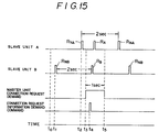
- FIG. 15 shows an operation sequence for establishing connections between the master and slave units of the audiovisual system.
- the master unit is disabled due to a temporary voltage drop, for example, or the user presses a reset switch upon a malfunction of the system at a time t0.
- the master unit fails to respond to a connection request R NA from a slave unit A at a time t2 and a connection request R NB from a slave unit B at a time t1.
- the slave controllers of the slave units A, B now serve as operation mode changing means. Thereafter, the slave units A, B enter a low power consumption mode (see FIG. 19 at (b)). Then, the slave units A, B temporarily enter a normal mode (see FIG.
- connection requests R NA , R NB to the master unit in each fixed time period (e.g., of 2 seconds) under the control of timers in their own controllers. If no response comes back from the master unit, the slave units A, B enter the low power consumption mode again.
- the master controller 18 When the master unit is subsequently enabled at a time t3, the master controller 18 functions as a connection request demand means, and sends a connection request demand command as connection request information demand data to all the slave units at a time t4.
- connection requests R A , R B In response to the connection request demand command from the master controller 18, the slave controllers of the slave units A, B send connection requests R A , R B within a wait time period (t3 ⁇ t5) of the master controller 18, at times different from the times for making normal connection requests.
- the master unit can cause all the slave controllers to make connection requests within a certain time period (e.g., of 1 second), the master unit can enable the entire data communication system within a predetermined time period.
- the above communication sequence is stored as a control program in the controllers of the master unit 200 and the slave units 200 ⁇ 1 ⁇ 200 -n .
- the other slaves operate in the same manner as the illustrated slave unit.
- the master unit 200 is enabled after it has failed to operate, issuing communication data DT1 as connection request information demand data to all the slave units 200 ⁇ 1 ⁇ 200 -n through the communication bus 14.
- the communication data DT1 has a format for sending connection information from the master unit 200 simultaneously to all the slave units 200 ⁇ 1 ⁇ 200 -n .
- the communication data DT1 will hereinafter be referred to as "multiaddress communication data". It is assumed that the physical address data representing each of the slave units 200 ⁇ 1 ⁇ 200 -n is of 12 bits.
- the master unit 200 can transmit the same connection request information demand data to all the slave units in one transmission process.
- each of the slave units issues and transmits return data RDT1, indicating that the check sum is agreed with, to the master unit.
- the master unit issues and transmits return data RDT2, indicating that the check sum is agreed with, to the slave unit.
- the above communication sequence allows the master unit to cause all the slave units to make connection requests in a short period of time, and hence to enable the overall system easily.
- connection request information demand data is transmitted to all the slave units. If a plurality of groups of slave units having different four high-order bits of the physical address data are connected to the same communication bus, then it is possible to transmit communication data as connection request information demand data simultaneously to only those slave units belonging to one group whose four high-order bits of the physical address data are identical.
- a modified data communication system has a first group (audiovisual group) of slave units having physical address data PA whose four high-order bits are "1H”, a second group (telephone group) of slave units having physical address data PA whose four high-order bits are "2H”, a third group (navigation group) of slave units having physical address data PA whose four high-order bits are "3H”, and a fourth group (FAX group) of slave units having physical address data PA whose four high-order bits are "4H".
- the connection request information demand data is transmitted simultaneously to only the slave units belonging to the second telephone group.
- each of the slave units when each of the slave units enters the low power consumption mode, it turns off the power supply for peripheral circuits and the slave controller is halted or held at rest, as shown in FIG. 19 at (b).
- the communication driver/receiver of the communication interface IC may be divided into a communication driver 32D and a communication receiver 32R, and only the communication receiver 32R as a data receiver may be energized in the low power consumption mode.
- the arrangement shown in FIG. 18 is effective to reduce the power consumption in the low power consumption mode.
- the slave controller when each of the slave units enters the low power consumption mode while it is standing by, the slave controller is halted. If the slave unit is required to stand by for a longer period of time, however, the slave controller may be brought into a stop mode or disabled after the low power consumption mode, as shown in FIG. 19(c), and may be enabled again in response to an interrupt caused by the reception of a connection request information demand command from the master unit. This is effective to further reduce the power consumption. The slave unit may enter the stop mode directly from the normal operation mode without the low power consumption mode.
- the return data is returned after having received the connection information.
- the return data may be dispensed with if the data communication system is highly reliable in data communication.
- the data communication system has only one master unit in the above embodiment.
- the present invention is also applicable to a data communication system having a plurality of master units, as shown in FIG. 20.
- the master controller of each of the master units is required to be allotted its own address (e.g., "300H" for a navigation master unit) in order to determine from or to which master unit the data is being transmitted.
- FIG. 21 schematically shows in block form a data communication system for use on an automobile according to a second embodiment of the present invention.
- the data communication system comprises at least one master unit 101A (101′A) connected to a communication bus 103 and a plurality of slave units 102 ⁇ 1A, 102 ⁇ 2A, ⁇ 102 ⁇ n A connected to the communication bus 103.
- Each of the slave units 102 ⁇ 1A ⁇ 102 -n A has a first memory 104A for storing connection information and a first connection information transmitter 105A for transmitting, to the master unit 101A (101′A), first change information indicative of whether the connection information of its own stored in the first memory 104A is identical to the connection information of its own that has previously been transmitted to the master unit 101A (101′A) or not.
- the master unit 101A (101′A) has a second memory 106A for storing connection information, and a second connection information transmitter 107A for transmitting the connection information stored in the second memory 106A to the slave units 102 ⁇ 1A ⁇ 102 -n A based on the first change information of the slave units 102 ⁇ 1A ⁇ 102 -n A.
- the first memory 104A stores connection information.
- the first connection information transmitter 105A transmits, to the master unit 101A (101′A), first change information indicative of whether the connection information of its own stored in the first memory 104A is identical to the connection information of its own that has previously been transmitted to the master unit 101A (101′A) or not.
- the second memory 106A stores connection information.
- the second connection information transmitter 107A transmits the connection information, partly or entirely, stored in the second memory 106A to the slave units 102 ⁇ 1A ⁇ 102 -n A based on the first change information of the slave units 102 ⁇ 1A ⁇ 102 -n A.
- the master and slave units of the data communication system are therefore capable of recognizing the latest connected state at all times, and may transmit connection information only when the connected state has changed.
- the data communication system can therefore effect data communication highly efficiently.
- the data communication system according to the second embodiment is particularly useful when embodied in an audiovisual (AV) system on an automobile.
- AV audiovisual
- the audiovisual system and data formats employed thereby are identical to those of the first embodiment described above, and hence will not be described in detail below.
- each of the slave units 200 ⁇ 1 ⁇ 200 -n transmits connection information of its own in the form of a self report (periodic communication), as connection request information, to the master unit 200 in each time period.
- a slave unit A makes a connection request at a time t1. Subsequently, the slave unit A makes a connection request in each time period (e.g., of 2 seconds). The master unit stores all connection requests made within a certain time period (e.g., of 5 seconds), and then transmits connection information to all slave units including the slave unit A at a time t2.
- the master unit determines whether there have been connection requests from all the slave units within a certain time period (e.g., of 5 seconds), for thereby checking the number and types of the connected slave units to confirm any slave units that have been disconnected or dropped from service or that have been newly added. For example, if a slave unit B which has been connected so far is disconnected at a time t3, then the master unit receives no connection request from the slave unit B at the time t2 when the master unit confirms the number of connected slave units. Thereafter, the master unit regards the slave unit B as being disconnected, and subsequently transmits the connection information of its own and of all the slave units except the slave unit B at the time t2.
- a certain time period e.g., of 5 seconds
- the master unit determines that the slave unit A has not requested a connection so far, and subsequently transmits the connection information of its own and of all the slave units including the slave unit A at the time t2.
- the data transfer sequences include a communication sequence for periodic communication and a communication sequence in the event that the number or types of connected slave units have changed.
- Basic algorithms for the communication sequence for periodic communication include A) a communication sequence algorithm to be followed when the connection information of slave units has not changed, B) a communication sequence algorithm to be followed when the connection information of slave units has changed, and C) a communication sequence algorithm to be followed when the connection information of a master unit has changed.
- the above communication sequences are stored as a control program in the controllers of the master unit 200 and the slave units 200 ⁇ 1 ⁇ 200 -n .
- Periodic communication for transmitting connection information will be described in detail below with reference to FIGS. 23 through 27.
- This periodic communication sequence is carried out when the connection information of a slave unit has not changed. According to this sequence, only data corresponding to first change information is transmitted, and the connection information of the slave unit is not transmitted.
- the master unit issues return data RDT1, indicating that the check sum is agreed with, to the slave unit.
- the slave unit issues return data RDT2, indicating that the check sum is agreed with, to the master unit.
- the master and slave units keep on holding the connection information which has been held without updating it, and effect data communication based on the connection information that is held.
- This periodic communication sequence is carried out when the connection information of a slave unit has changed. According to this sequence, after the master unit has received communication data from a slave unit, the master unit transmits connection information of all the slave units.
- the master unit issues return data RDT3, indicating that the connection information has been received, to the slave unit.
- the connection information SL2 ⁇ SL n of the other slave units also has the same contents as described above.
- the slave unit issues return data RDT4 to the master unit.
- each of the slave units updates the connection information which has been held so far, and effects subsequent communication with the master unit based on the new connection information.
- This periodic communication sequence is carried out when the connection information of a slave unit has changed. According to this sequence, the master unit transmits only the connection information, which has changed, of a slave unit to all the slave units.
- the slave unit issues and transmits communication data DT5, as shown in FIG. 25, through the communication bus 14 to the master unit to transfer its own connection information that has changed.
- the master unit issues return data RDT5, indicating that the connection information has been received, to the slave unit.
- the slave unit issues return data RDT6 to the master unit.
- each of the slave units updates only a newly notified portion of the connection information which has been held so far, and effects subsequent communication with the master unit based on the new connection information.
- the master unit Since the master unit is not required to transmit all connection information, but to transmit only the connection information, which has changed, of the slave unit, the time in which the communication bus is occupied by the transmission of the connection information is shortened.
- This periodic communication sequence is carried out when the connection information of a master unit has changed. According to this sequence, the master unit transmits its own connection information that has changed and connection information of all the slave units.
- the master unit issues and transmits communication data DT7, as shown in FIG. 26, through the communication bus 14 to all the slave units to transfer its own connection information that has changed.
- connection information SL1 ⁇ SL n of all the slave units are also added as described above.
- the slave unit issues return data RDT7 to the master unit.
- each of the slave units updates the connection information which has been held so far, and effects subsequent communication with the master unit based on the new connection information.
- This periodic communication sequence is carried out when the connection information of a master unit has changed. According to this sequence, the master unit transmits its own connection information that has changed and does not transmit connection information of all the slave units.
- the master unit issues and transmits communication data DT8, as shown in FIG. 27, through the communication bus 14 to all the slave units to transfer its own connection information that has changed.
- the slave unit issues return data RDT8 to the master unit.
- each of the slave units updates only the connection information, which has been held so far, of the master unit, and effects subsequent communication with the master unit based on the new connection information.
- communication data DT9 (see FIG. 30) is normally transmitted as connection information from the master unit to all the slave units.
- the slave unit issues return data RDT9 to the master unit.
- the master unit regards the slave unit 200 -n-1 as being disconnected from the communication bus through comparison with the previous connection information.
- the master unit determines that the connected state has changed, and issues and transmits communication data DT10 to all the slave units (see FIG. 30).
- the slave unit issues return data RDT9 to the master unit.
- communication data DT11 (see FIG. 32) is normally transmitted as connection information from the master unit to all the slave units.
- the slave unit issues return data RDT11 to the master unit.
- the master unit determines that the slave unit 200 -NEW has been newly connected through comparison with the previous connection information.
- the master unit determines that the connected state has changed, and issues and transmits communication data DT12 to all the slave units (see FIG. 32).
- the slave unit issues return data RDT12 to the master unit.
- slave unit 200 -NEW has been connected to the communication bus, and can communicate with each other and the newly connected slave unit 200 -NEW .
- the number of connected slave units is changed.
- the aforesaid communication sequences at the time a slave unit is disconnected and a slave unit is newly connected are carried out.
- connection information is transmitted from the master unit individually to the slave units.
- connection information is transmitted from the master unit simultaneously to all the slave units or a plurality of slave units of all the slave units.
- communication data DT13 has a format for sending connection information from the master unit simultaneously slave units that have been selected by the master unit. Such communication data that is simultaneously transmitted is called "multiaddress communication data". It is assumed that the physical address data representing each of the slave units is of 12 bits.
- the master unit can transmit the same connection request information demand data to all the slave units in one transmission process, so that the time in which the communication bus is occupied by the transmission of the connection information is shortened. Thereafter, each of the slave units transmits return data indicating that the connection information has received, back to the master unit.
- connection information is transmitted from the master unit simultaneously to all the slave units.
- a plurality of groups of slave units whose physical address data PA have different four high-order bits are connected to one communication bus, it is possible to transmit connection information simultaneously only to those slave units which belong to a group or groups whose physical address data PA have the same four high-order bits.
- FIG. 34 shows a data communication system having a first group (audiovisual group) of slave units having physical address data PA whose four high-order bits are "1H", a second group (telephone group) of slave units having physical address data PA whose four high-order bits are "2H", a third group (navigation group) of slave units having physical address data PA whose four high-order bits are "3H”, and a fourth group (FAX group) of slave units having physical address data PA whose four high-order bits are "4H”.
- FIG. 35 schematically shows in block form a data communication system for use on an automobile according to a fourth embodiment of the present invention.
- the data communication system comprises at least one master unit 101B (101′B) connected to a communication bus 103 and a plurality of slave units 102 ⁇ 1B, 102 ⁇ 2B, ⁇ 102 ⁇ n B connected to the communication bus 103.
- Each of the slave units 102 ⁇ 1B ⁇ 102 -n B has a memory 104B for storing its own communication address updatably, and a connection request unit 105B for transmitting its own connection request information to the master unit 101B (101′B) when the data communication system is enabled or starts to operate.
- the master unit 101B (101′B) has a communication address setting unit 106B, which when the connection request information is received from the slave units, establishes communication addresses for the slave units, different from those of the other slave units, and informs the slave units of the established communication addresses.
- connection request unit 105B of the respective slave units 102 ⁇ 1B, 102 ⁇ 2B, ⁇ 102 -n B transmit their own connection request information to the master unit 101B (101′B).
- the communication address setting unit 106B establishes communication addresses for the slave units, different from those of the other slave units, and sends the established communication addresses to the slave units.
- the memory 104B of the respective slave units 102 ⁇ 1B, 102 ⁇ 2B, ⁇ 102 -n B store their own communication addresses sent from the master unit 101B (101′B). Therefore, the different communication addresses are set up for the respective slave units 102 ⁇ 1B, 102 ⁇ 2B, ⁇ 102 -n B.
- the data communication system according to the fourth embodiment of the present invention will be described in detail below.
- the data communication system according to the fourth embodiment is particularly useful when embodied in an audiovisual (AV) system on an automobile.
- the data formats employed by the audiovisual system are identical to those of the first embodiment described above, and hence will not be described in detail below.
- FIG. 36 shows a detailed systematic arrangement of the audiovisual system.
- the audiovisual system has audio reproducing components and visual reproducing components.
- the audio reproducing components include a cassette tape deck 6 for reproducing recorded audio signals from a cassette tape 1, a tuner 7 such as an AM/FM tuner for reproducing radio signals which are received by an antenna 2, a multiple CD player 9A having an automatic CD changer 5A for reproducing recorded signals from multiple CDs 4A, and a multiple CD player 9B having an automatic CD changer 5B for reproducing recorded signals from multiple CDs 4B.
- the visual reproducing components include a TV tuner contained in the tuner 7, for reproducing TV signals received by the antenna 2, and a display unit 12 for displaying images based on the TV signals and also displaying still images based on signals from the CD players 9A, 9B if a CD-ROM is played back by the CD players 9A, 9B.
- a CD-ROM is employed by a navigation system.
- the audiovisual system has an external commander 10 which is in the form of a keyboard for entering various operation commands.
- a display unit 11 is connected to the external commander 10.
- the audiovisual system also has an input unit 13, which may be incorporated in the external commander 10.
- the above components of the audiovisual system have respective controllers for controlling their own operation. These controllers are connected to each other through a communication bus 14, thereby making up a communication bus control network.
- the control network is shown in FIG. 4.
- Reproduced signals S1 from the audio reproducing components are selectively applied through a selector 15 as a reproduced signal S2 to a digital amplifier 16.
- a selector 15 After the reproduced signal S2 has been amplified by the digital amplifier 16, it is applied as reproduced signals S3 to loudspeakers 17 from which the reproduced sounds S3 are outputted.
- the digital amplifier 16 contains a digital signal processing circuit which is controlled by a controller in the digital amplifier 16, the controller being connected to the communication bus 14.
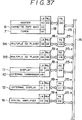
- FIG. 37 shows an example in which the units shown in FIG. 36 are allotted physical address data PA.
- the physical address data PA are established for master and slave controllers 18 ⁇ 18 ⁇ 5. This is to take into account the fact that two functional elements, such as the cassette tape deck 6 and the tuner 7, are connected to one master controller 18, as with the master unit 200 (see FIG. 4). If one controller is combined with one function, then the physical address data PA and the logical address data LA indicate the same address, as with slave controllers 18 ⁇ 1, 18 ⁇ 2, 18 ⁇ 5.
- the above communication sequence is stored as a control program in the controllers of the master unit 200 and the slave units 200 ⁇ 1 ⁇ 200 -n .
- the connected state of the slave units 200 ⁇ 1 ⁇ 200 -n when their power supplies are turned off is stored in the RAM M10 (see FIG. 4) of the master unit 200, and the slave units 200 ⁇ 1 ⁇ 200 -n store their own established communication addresses in their respective memories M11 ⁇ M 1n (see FIG. 4).
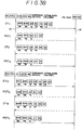
- FIG. 38 shows a specific communication sequence in which two slave units, e.g., the multiple CD players 9A, 9B, make a connection request to and access the master unit for established communication addresses when the audiovisual system starts to operate.
- two slave units e.g., the multiple CD players 9A, 9B
- the multiple CD player 9A issues and transmits communication data DT1 through the communication bus 14 to the master unit for a connection request by way of a self report.
- the temporary communication address may be selected as desired.
- temporary communication addresses should desirably be grouped according to function, e.g., "1FFH” for audio components, "2FFH” for navigation components, "3FFH” for telephone components, and "4FFH” for facsimile components, so that temporary communication addresses can be set for respective groups.
- the master unit In response to the communication data DT1, the master unit transmits return data RDT1 back to the slave unit, indicating that the master unit has received the communication data DT1.
- the master unit issues and transmits communication data DT2 through the communication bus 14 to the slave unit in order to give the established communication address to the slave unit.
- the master unit will handle the slave unit as an audiovisual system member.
- the slave unit In response to the communication data DT2, the slave unit transmits return data RDT2 back to the master unit, indicating that the slave unit has received the communication data DT2.
- the other slave unit i.e., the multiple CD player 9B
- the communication data DT3 is not accepted by the master unit while the multiple CD player 9A is communicating with the master unit.
- the communication data DT3 is transmitted through the communication bus 14 to the master unit.
- the master unit In response to the communication data DT3, the master unit transmits return data RDT3 back to the slave unit, indicating that the master unit has received the communication data DT3.
- the master unit issues and transmits communication data DT4 through the communication bus 14 to the slave unit in order to give the established communication address to the slave unit.
- the master unit will handle the slave unit as another audiovisual system member.
- the slave unit In response to the communication data DT4, the slave unit transmits return data RDT4 back to the master unit, indicating that the slave unit has received the communication data DT4.
- the groups of slave units e.g., the audiovisual, telephone, navigation, and FAX groups
- the master units recognize the slave units to be controlled thereby in the respective groups based on the temporary communication addresses, and establish communication addresses for the slave units to be controlled.
- the audiovisual group may be allotted a temporary communication address of "1FFH”
- the navigation group may be allotted a temporary communication address of "3FFH”.
Landscapes
- Engineering & Computer Science (AREA)
- Computer Hardware Design (AREA)
- Theoretical Computer Science (AREA)
- Software Systems (AREA)
- Physics & Mathematics (AREA)
- General Engineering & Computer Science (AREA)
- General Physics & Mathematics (AREA)
- Small-Scale Networks (AREA)
- Selective Calling Equipment (AREA)
Applications Claiming Priority (9)
| Application Number | Priority Date | Filing Date | Title |
|---|---|---|---|
| JP97673/91 | 1991-04-26 | ||
| JP9767391 | 1991-04-26 | ||
| JP9767391A JPH04326896A (ja) | 1991-04-26 | 1991-04-26 | 車載用データ通信システム |
| JP11772691 | 1991-05-22 | ||
| JP3117727A JP3045326B2 (ja) | 1991-05-22 | 1991-05-22 | 車載用データ通信システム |
| JP117726/91 | 1991-05-22 | ||
| JP117727/91 | 1991-05-22 | ||
| JP11772791 | 1991-05-22 | ||
| JP03117726A JP3100997B2 (ja) | 1991-05-22 | 1991-05-22 | 車載用データ通信システム |
Publications (3)
| Publication Number | Publication Date |
|---|---|
| EP0511794A1 true EP0511794A1 (de) | 1992-11-04 |
| EP0511794B1 EP0511794B1 (de) | 1995-07-19 |
| EP0511794B2 EP0511794B2 (de) | 2002-03-13 |
Family
ID=27308467
Family Applications (1)
| Application Number | Title | Priority Date | Filing Date |
|---|---|---|---|
| EP92303728A Expired - Lifetime EP0511794B2 (de) | 1991-04-26 | 1992-04-24 | Datenübertragungssystem in einem Fahrzeug |
Country Status (3)
| Country | Link |
|---|---|
| US (1) | US5305355A (de) |
| EP (1) | EP0511794B2 (de) |
| DE (1) | DE69203525T3 (de) |
Cited By (12)
| Publication number | Priority date | Publication date | Assignee | Title |
|---|---|---|---|---|
| EP0608624A3 (en) * | 1992-12-28 | 1994-09-14 | Sony Corp | Hierarchical control system for av equipment and method of setting up such a system. |
| WO1998011700A1 (de) * | 1996-09-12 | 1998-03-19 | Robert Bosch Gmbh | Verfahren zur kontrolle der verbindungen eines übertragungssystems und komponente zur durchführung des verfahrens |
| EP0778179A3 (de) * | 1995-11-20 | 1998-05-20 | Alps Electric Co., Ltd. | Multiplexiertes Kommunikationssystem |
| DE19754640A1 (de) * | 1997-12-09 | 1999-06-10 | Bosch Gmbh Robert | Verfahren zur Koordination von Netzwerkkomponenten |
| EP0874502A3 (de) * | 1997-04-25 | 1999-07-07 | Yazaki Corporation | Kommunikationssystem und Datenformat zur Anwendung dafür |
| EP0637140A3 (de) * | 1993-07-30 | 2000-01-12 | Sony Corporation | Konfigurationsverfahren für ein Audio-Video-Gerät mit digitaler Busschnittstelle |
| EP1006024A3 (de) * | 1998-11-30 | 2000-09-13 | DaimlerChrysler Corporation | Kommunikationssystem |
| EP1146494A1 (de) * | 2000-03-29 | 2001-10-17 | Wittig Test Technology GmbH | Funkgesteuerte Handmessgeräte im Master-/Slave-Betrieb |
| WO2003057537A1 (es) * | 2000-12-26 | 2003-07-17 | Lear Automotive (Eeds) Spain,S.L. | Sistema distribuido y procedimiento de adquisicion de datos a distancia, en paquetes con protocolo de comunicacion que optimiza la velocidad de transmision |
| EP0862290A3 (de) * | 1996-11-21 | 2004-01-07 | Yazaki Corporation | Sender, Empfänger, Kommunikationsgerät, Kommunikations-Verfahren und -System |
| EP1069510A3 (de) * | 1999-07-14 | 2006-08-09 | Grundig Multimedia B.V. | Verfahren zur Aufnahme einer neuen Komponente in einem Bussystem |
| EP1699179A1 (de) * | 2005-03-01 | 2006-09-06 | Valeo Systemes Thermiques | Verfahren zur Datenübertragung von Slave-Endgeräten an ein Master-Endgerät gemäß einem Kommunikationsbus |
Families Citing this family (31)
| Publication number | Priority date | Publication date | Assignee | Title |
|---|---|---|---|---|
| US5625350A (en) * | 1993-12-27 | 1997-04-29 | Alpine Electronics, Inc. | Audio/video communication system and method |
| US6002490A (en) * | 1993-12-30 | 1999-12-14 | Ricoh Company, Ltd. | Color digital image composing apparatus |
| JPH07327277A (ja) * | 1994-05-31 | 1995-12-12 | Sony Corp | 電子機器装置および接続用コネクタ |
| JP3681186B2 (ja) * | 1994-06-22 | 2005-08-10 | パイオニア株式会社 | リモートコントロールシステム |
| JP3099663B2 (ja) * | 1995-02-09 | 2000-10-16 | 株式会社デンソー | 通信システム |
| US6114970A (en) * | 1997-01-09 | 2000-09-05 | Motorola, Inc. | Method of assigning a device identification |
| US6324592B1 (en) * | 1997-02-25 | 2001-11-27 | Keystone Aerospace | Apparatus and method for a mobile computer architecture and input/output management system |
| GB9718722D0 (en) * | 1997-09-04 | 1997-11-12 | Comm & Control Electronics Ltd | Local communication system |
| CN1187963C (zh) * | 1997-09-11 | 2005-02-02 | 索尼公司 | 用于选择音响影像设备的输入和输出的电子设备 |
| JP3733709B2 (ja) * | 1997-09-30 | 2006-01-11 | ソニー株式会社 | 電子機器、電源制御方法及び記録媒体 |
| ATE317564T1 (de) * | 2000-04-10 | 2006-02-15 | Zensys As | Rf-gesteuertes hausautomatisierungssystem mit doppelfunktionalen netzknoten |
| US6785748B2 (en) | 2000-07-18 | 2004-08-31 | Canon Kabushiki Kaisha | Image communication apparatus wirelessly connectable to other apparatuses, system having the image communication apparatus, and method for controlling the same |
| WO2005049357A2 (en) * | 2003-11-18 | 2005-06-02 | The Braun Corporation | Electronic control system and method for an auxiliary device interlock safety system |
| US7394775B2 (en) * | 2000-12-26 | 2008-07-01 | Lear Corp. | Distributed system and method for the remote acquisition of data in packets with a communication protocol which optimizes the transmission speed |
| JP2002236630A (ja) * | 2001-02-08 | 2002-08-23 | Fujitsu Ltd | 処理装置、管理装置、コンピュータシステム、記録媒体およびプログラム |
| TW561725B (en) * | 2001-02-14 | 2003-11-11 | Matsushita Electric Industrial Co Ltd | Communications setting method and communications setting system for power line communications system |
| JP2004126646A (ja) * | 2002-09-30 | 2004-04-22 | Canon Inc | バス制御方法 |
| US7769346B1 (en) * | 2003-10-31 | 2010-08-03 | Johnson Controls Technology Company | Wireless electrical connectivity system for use in a vehicle |
| US9175977B2 (en) * | 2005-12-20 | 2015-11-03 | General Motors Llc | Method for arbitrating between multiple vehicle navigation systems |
| US7417395B2 (en) * | 2006-05-18 | 2008-08-26 | The Braun Corporation | Switch-based door and ramp interface system |
| WO2008022078A2 (en) * | 2006-08-17 | 2008-02-21 | The Braun Corporation | Door and ramp interface system |
| WO2008070779A2 (en) * | 2006-12-06 | 2008-06-12 | The Braun Corporation | Wireless vehicle access control system |
| JP2008148252A (ja) * | 2006-12-13 | 2008-06-26 | Toshiba Corp | 無線通信装置、通信レート設定方法、及び通信レート設定プログラム |
| US7816878B2 (en) * | 2007-02-01 | 2010-10-19 | The Braun Corporation | Vehicle access control system |
| US8244949B2 (en) * | 2007-05-18 | 2012-08-14 | Nec Infrontia Corporation | Slot interface access unit, method thereof, and program thereof, as well as redundancy configuration of main unit, and replacing method of the same |
| EP2664488B1 (de) * | 2007-09-11 | 2016-07-27 | Hydro-Gear Limited Partnership | Antriebssteuerungen und -verfahren für ein Elektronutzfahrzeug |
| US8207693B2 (en) | 2007-09-11 | 2012-06-26 | Hydro-Gear Limited Partnership | Controller assemblies for electric drive utility vehicles |
| US8838850B2 (en) * | 2008-11-17 | 2014-09-16 | Violin Memory, Inc. | Cluster control protocol |
| US8050673B2 (en) | 2008-12-29 | 2011-11-01 | General Motors Llc | Primary connection strategy for vehicle originated cellular communication to a call center |
| US8775714B2 (en) * | 2012-01-30 | 2014-07-08 | Infineon Technologies Ag | System and method for a bus interface |
| KR102450296B1 (ko) | 2017-12-26 | 2022-10-04 | 삼성전자주식회사 | 동기식 및 비동기식 혼합 방식의 디지털 인터페이스를 포함하는 장치, 이를 포함하는 디지털 처리 시스템, 및 이들에 의해 수행되는 디지털 처리 방법 |
Citations (5)
| Publication number | Priority date | Publication date | Assignee | Title |
|---|---|---|---|---|
| FR2445769A1 (fr) * | 1979-01-04 | 1980-08-01 | Renault | Dispositif de distribution d'energie electrique a bord d'un vehicule, par exemple a moteur |
| EP0289779A2 (de) * | 1987-04-07 | 1988-11-09 | Siemens Nixdorf Informationssysteme Aktiengesellschaft | Verfahren zur anfänglichen Identifizierung und Änderung der Identifizierung der Moduln eines hochverfügbaren Computers |
| EP0295475A2 (de) * | 1987-06-15 | 1988-12-21 | International Business Machines Corporation | Verfahren zur Instandhaltung einer Netzstruktur-Datenbank |
| WO1989002141A1 (en) * | 1987-09-04 | 1989-03-09 | Ab Thoreb | Method and system for transmitting information and controlling components |
| EP0327456A1 (de) * | 1988-02-05 | 1989-08-09 | Siemens Automotive S.A. | System zum Setzen von mit einem Übertragungskanal verbundenen, elektronischen Gehäusen in Betriebzustand und in wachen Zustand |
Family Cites Families (8)
| Publication number | Priority date | Publication date | Assignee | Title |
|---|---|---|---|---|
| DE3335932A1 (de) * | 1983-10-04 | 1985-04-18 | Wabco Westinghouse Fahrzeugbremsen GmbH, 3000 Hannover | Einrichtung zum abfragen und steuern von mehreren komponeneten eines fahrzeuges |
| JPH0783368B2 (ja) * | 1985-03-27 | 1995-09-06 | 株式会社日立製作所 | 多元情報伝送システム |
| US4742335A (en) * | 1986-06-18 | 1988-05-03 | Baker Industries, Inc. | Sequential and/or random polling system with virtually instantaneous response time |
| EP0283295B1 (de) * | 1987-03-20 | 1993-09-08 | Canon Kabushiki Kaisha | Datenübertragungssystem |
| US4855730A (en) * | 1987-05-08 | 1989-08-08 | Rca Licensing Corporation | Component audio/video system with timed control of plural peripheral devices |
| NL8800639A (nl) * | 1988-03-16 | 1989-10-16 | Philips Nv | Eenkanaalskommunikatiebussysteem en station voor gebruik in zo een kommunikatiebussysteem. |
| DE3809129C2 (de) * | 1988-03-18 | 1994-06-09 | Broadcast Television Syst | Verfahren und Vorrichtung zur Steuerung von videotechnischen Geräten |
| EP0432316A1 (de) * | 1989-12-14 | 1991-06-19 | Koninklijke Philips Electronics N.V. | Lokales Kommunikationsbussystem mit einer Anzahl miteinander verbundener Einrichtungen, einem Steuerbus und einer Anzahl von Signalverbindungen sowie einer Einrichtung und einem Schaltkasten zur Verwendung in einem derartigen System |
-
1992
- 1992-04-24 EP EP92303728A patent/EP0511794B2/de not_active Expired - Lifetime
- 1992-04-24 DE DE69203525T patent/DE69203525T3/de not_active Expired - Fee Related
- 1992-04-27 US US07/874,968 patent/US5305355A/en not_active Expired - Lifetime
Patent Citations (5)
| Publication number | Priority date | Publication date | Assignee | Title |
|---|---|---|---|---|
| FR2445769A1 (fr) * | 1979-01-04 | 1980-08-01 | Renault | Dispositif de distribution d'energie electrique a bord d'un vehicule, par exemple a moteur |
| EP0289779A2 (de) * | 1987-04-07 | 1988-11-09 | Siemens Nixdorf Informationssysteme Aktiengesellschaft | Verfahren zur anfänglichen Identifizierung und Änderung der Identifizierung der Moduln eines hochverfügbaren Computers |
| EP0295475A2 (de) * | 1987-06-15 | 1988-12-21 | International Business Machines Corporation | Verfahren zur Instandhaltung einer Netzstruktur-Datenbank |
| WO1989002141A1 (en) * | 1987-09-04 | 1989-03-09 | Ab Thoreb | Method and system for transmitting information and controlling components |
| EP0327456A1 (de) * | 1988-02-05 | 1989-08-09 | Siemens Automotive S.A. | System zum Setzen von mit einem Übertragungskanal verbundenen, elektronischen Gehäusen in Betriebzustand und in wachen Zustand |
Cited By (19)
| Publication number | Priority date | Publication date | Assignee | Title |
|---|---|---|---|---|
| US5796352A (en) * | 1992-12-28 | 1998-08-18 | Sony Corporation | Audio video equipment system with bus line and method of establishing a connection setting for the audio video equipment system |
| EP0608624A3 (en) * | 1992-12-28 | 1994-09-14 | Sony Corp | Hierarchical control system for av equipment and method of setting up such a system. |
| EP0637140A3 (de) * | 1993-07-30 | 2000-01-12 | Sony Corporation | Konfigurationsverfahren für ein Audio-Video-Gerät mit digitaler Busschnittstelle |
| EP0778179A3 (de) * | 1995-11-20 | 1998-05-20 | Alps Electric Co., Ltd. | Multiplexiertes Kommunikationssystem |
| WO1998011700A1 (de) * | 1996-09-12 | 1998-03-19 | Robert Bosch Gmbh | Verfahren zur kontrolle der verbindungen eines übertragungssystems und komponente zur durchführung des verfahrens |
| US6643689B2 (en) | 1996-09-12 | 2003-11-04 | Robert Bosch Gmbh | Process and components for controlling the connections of a transmission system |
| EP1633065A3 (de) * | 1996-11-21 | 2008-05-14 | Yazaki Corporation | Sender, Empfänger, Kommunikationsgerät, Kommunikationsverfahren und -system |
| EP0862290A3 (de) * | 1996-11-21 | 2004-01-07 | Yazaki Corporation | Sender, Empfänger, Kommunikationsgerät, Kommunikations-Verfahren und -System |
| US6470012B2 (en) | 1997-04-25 | 2002-10-22 | Yazaki Corporation | Communication system and data-format to be used in the same |
| EP0874502A3 (de) * | 1997-04-25 | 1999-07-07 | Yazaki Corporation | Kommunikationssystem und Datenformat zur Anwendung dafür |
| DE19754640A1 (de) * | 1997-12-09 | 1999-06-10 | Bosch Gmbh Robert | Verfahren zur Koordination von Netzwerkkomponenten |
| US7283488B2 (en) | 1998-11-30 | 2007-10-16 | Chrysler Llc | J1850 application specific integrated circuit (ASIC) and messaging technique |
| EP1006024A3 (de) * | 1998-11-30 | 2000-09-13 | DaimlerChrysler Corporation | Kommunikationssystem |
| EP1069510A3 (de) * | 1999-07-14 | 2006-08-09 | Grundig Multimedia B.V. | Verfahren zur Aufnahme einer neuen Komponente in einem Bussystem |
| WO2001073953A3 (de) * | 2000-03-29 | 2002-05-23 | Wittig Test Technology Gmbh | Funkgesteuerte handmessgeräte im master-/slave-betrieb |
| EP1146494A1 (de) * | 2000-03-29 | 2001-10-17 | Wittig Test Technology GmbH | Funkgesteuerte Handmessgeräte im Master-/Slave-Betrieb |
| WO2003057537A1 (es) * | 2000-12-26 | 2003-07-17 | Lear Automotive (Eeds) Spain,S.L. | Sistema distribuido y procedimiento de adquisicion de datos a distancia, en paquetes con protocolo de comunicacion que optimiza la velocidad de transmision |
| EP1699179A1 (de) * | 2005-03-01 | 2006-09-06 | Valeo Systemes Thermiques | Verfahren zur Datenübertragung von Slave-Endgeräten an ein Master-Endgerät gemäß einem Kommunikationsbus |
| FR2882836A1 (fr) * | 2005-03-01 | 2006-09-08 | Valeo Systemes Thermiques | Procede de transmission de donnees de terminaux-esclaves vers un terminal-maitre le long d'un bus de communication. |
Also Published As
| Publication number | Publication date |
|---|---|
| DE69203525D1 (de) | 1995-08-24 |
| EP0511794B2 (de) | 2002-03-13 |
| US5305355A (en) | 1994-04-19 |
| DE69203525T3 (de) | 2002-08-08 |
| DE69203525T2 (de) | 1996-03-28 |
| EP0511794B1 (de) | 1995-07-19 |
Similar Documents
| Publication | Publication Date | Title |
|---|---|---|
| US5305355A (en) | System for data communication on automobile | |
| EP0482957B1 (de) | Verfahren zür Datenübertragung in einem Kommunikationsnetzwerk eines Automobiles | |
| US5697048A (en) | On-vehicle data communication system and method | |
| EP0515042B1 (de) | Datenübertragungssystem in einem Fahrzeug | |
| EP0511795A1 (de) | System und Verfahren für Datenübertragung in einem Fahrzeug | |
| US6823399B2 (en) | Apparatus control method and transmission device | |
| US5280281A (en) | Method of and system for data communication in communication network on automobile | |
| EP0511010A2 (de) | Datenkommunikationssystem eines Autos | |
| EP0482959B1 (de) | System zur Datenübertragung | |
| EP0482951B1 (de) | Verfahren und System zur Datenübertragung in einem Kraftfahrzeug-Übertragungsnetz | |
| JP3100997B2 (ja) | 車載用データ通信システム | |
| EP0482958B1 (de) | System zür Datenübertragung | |
| JP3199084B2 (ja) | Avシステムのリモートコントロール方法 | |
| EP0511793A1 (de) | Datenübertragungssystem in einem Fahrzeug | |
| EP0482952B1 (de) | Verfahren zur Datenübertragung in einem Kraftfahrzeugübertragungsnetz | |
| JPH04326896A (ja) | 車載用データ通信システム | |
| JP3045326B2 (ja) | 車載用データ通信システム | |
| JP3065651B2 (ja) | 車載用通信ネットワークにおけるデータ通信方法 | |
| JPS63282075A (ja) | エレベ−タの制御信号伝送装置 | |
| JP2966502B2 (ja) | 車載用通信ネットワークにおけるデータ通信方法 | |
| JPH04160940A (ja) | 車載用通信ネットワークにおけるデータ通信方法 | |
| JPH04326900A (ja) | 車載用データ通信システム | |
| JP3090463B2 (ja) | データ通信システム | |
| JPH04160943A (ja) | オーディオシステムにおけるデータ通信方法 | |
| JPH07177579A (ja) | 車載用機器制御システム |
Legal Events
| Date | Code | Title | Description |
|---|---|---|---|
| PUAI | Public reference made under article 153(3) epc to a published international application that has entered the european phase |
Free format text: ORIGINAL CODE: 0009012 |
|
| AK | Designated contracting states |
Kind code of ref document: A1 Designated state(s): DE FR GB |
|
| 17P | Request for examination filed |
Effective date: 19921028 |
|
| 17Q | First examination report despatched |
Effective date: 19940113 |
|
| GRAA | (expected) grant |
Free format text: ORIGINAL CODE: 0009210 |
|
| AK | Designated contracting states |
Kind code of ref document: B1 Designated state(s): DE FR GB |
|
| PG25 | Lapsed in a contracting state [announced via postgrant information from national office to epo] |
Ref country code: FR Effective date: 19950719 |
|
| REF | Corresponds to: |
Ref document number: 69203525 Country of ref document: DE Date of ref document: 19950824 |
|
| EN | Fr: translation not filed | ||
| PLBI | Opposition filed |
Free format text: ORIGINAL CODE: 0009260 |
|
| PG25 | Lapsed in a contracting state [announced via postgrant information from national office to epo] |
Ref country code: GB Effective date: 19960424 |
|
| 26 | Opposition filed |
Opponent name: ROBERT BOSCH GMBH Effective date: 19960309 |
|
| PLBF | Reply of patent proprietor to notice(s) of opposition |
Free format text: ORIGINAL CODE: EPIDOS OBSO |
|
| PLBF | Reply of patent proprietor to notice(s) of opposition |
Free format text: ORIGINAL CODE: EPIDOS OBSO |
|
| PLBF | Reply of patent proprietor to notice(s) of opposition |
Free format text: ORIGINAL CODE: EPIDOS OBSO |
|
| GBPC | Gb: european patent ceased through non-payment of renewal fee |
Effective date: 19960424 |
|
| RDAH | Patent revoked |
Free format text: ORIGINAL CODE: EPIDOS REVO |
|
| APAC | Appeal dossier modified |
Free format text: ORIGINAL CODE: EPIDOS NOAPO |
|
| APAE | Appeal reference modified |
Free format text: ORIGINAL CODE: EPIDOS REFNO |
|
| APAC | Appeal dossier modified |
Free format text: ORIGINAL CODE: EPIDOS NOAPO |
|
| APAE | Appeal reference modified |
Free format text: ORIGINAL CODE: EPIDOS REFNO |
|
| APCC | Communication from the board of appeal sent |
Free format text: ORIGINAL CODE: EPIDOS OBAPO |
|
| APCC | Communication from the board of appeal sent |
Free format text: ORIGINAL CODE: EPIDOS OBAPO |
|
| APAC | Appeal dossier modified |
Free format text: ORIGINAL CODE: EPIDOS NOAPO |
|
| PLAW | Interlocutory decision in opposition |
Free format text: ORIGINAL CODE: EPIDOS IDOP |
|
| PLAW | Interlocutory decision in opposition |
Free format text: ORIGINAL CODE: EPIDOS IDOP |
|
| PUAH | Patent maintained in amended form |
Free format text: ORIGINAL CODE: 0009272 |
|
| STAA | Information on the status of an ep patent application or granted ep patent |
Free format text: STATUS: PATENT MAINTAINED AS AMENDED |
|
| 27A | Patent maintained in amended form |
Effective date: 20020313 |
|
| AK | Designated contracting states |
Kind code of ref document: B2 Designated state(s): DE FR GB |
|
| EN | Fr: translation not filed | ||
| APAH | Appeal reference modified |
Free format text: ORIGINAL CODE: EPIDOSCREFNO |
|
| PGFP | Annual fee paid to national office [announced via postgrant information from national office to epo] |
Ref country code: DE Payment date: 20090420 Year of fee payment: 18 |
|
| PG25 | Lapsed in a contracting state [announced via postgrant information from national office to epo] |
Ref country code: DE Free format text: LAPSE BECAUSE OF NON-PAYMENT OF DUE FEES Effective date: 20101103 |