EP0512414A2 - Clapet coupe-feu - Google Patents
Clapet coupe-feu Download PDFInfo
- Publication number
- EP0512414A2 EP0512414A2 EP92107390A EP92107390A EP0512414A2 EP 0512414 A2 EP0512414 A2 EP 0512414A2 EP 92107390 A EP92107390 A EP 92107390A EP 92107390 A EP92107390 A EP 92107390A EP 0512414 A2 EP0512414 A2 EP 0512414A2
- Authority
- EP
- European Patent Office
- Prior art keywords
- fire damper
- profile
- flap leaf
- strip
- frame
- Prior art date
- Legal status (The legal status is an assumption and is not a legal conclusion. Google has not performed a legal analysis and makes no representation as to the accuracy of the status listed.)
- Withdrawn
Links
Images

Classifications
-
- A—HUMAN NECESSITIES
- A62—LIFE-SAVING; FIRE-FIGHTING
- A62C—FIRE-FIGHTING
- A62C2/00—Fire prevention or containment
- A62C2/06—Physical fire-barriers
- A62C2/12—Hinged dampers
-
- F—MECHANICAL ENGINEERING; LIGHTING; HEATING; WEAPONS; BLASTING
- F24—HEATING; RANGES; VENTILATING
- F24F—AIR-CONDITIONING; AIR-HUMIDIFICATION; VENTILATION; USE OF AIR CURRENTS FOR SCREENING
- F24F13/00—Details common to, or for air-conditioning, air-humidification, ventilation or use of air currents for screening
- F24F13/08—Air-flow control members, e.g. louvres, grilles, flaps or guide plates
- F24F13/10—Air-flow control members, e.g. louvres, grilles, flaps or guide plates movable, e.g. dampers
- F24F13/14—Air-flow control members, e.g. louvres, grilles, flaps or guide plates movable, e.g. dampers built up of tilting members, e.g. louvre
- F24F13/1406—Air-flow control members, e.g. louvres, grilles, flaps or guide plates movable, e.g. dampers built up of tilting members, e.g. louvre characterised by sealing means
Definitions
- the invention relates to a fire damper from a basic housing in which a damper blade is rotatably arranged, which is connected to an actuating lever mechanism.
- Such fire dampers are known in many forms and designs. They are usually used in appropriate ventilation systems and should be designed so that they close in the event of a fire and thus prevent the fire from spreading from one room to another through this ventilation system. Therefore, the damper leaf, which causes the closure, is normally held in the open position, which is carried out by a corresponding adjusting lever mechanism. In the event of a fire, this lever mechanism should automatically close the damper blade.
- the fire dampers on the market have various disadvantages. On the one hand, there are usually fire dampers with many welds, which not only makes the manufacture of these fire dampers more expensive, but also pollutes the environment.
- control lever mechanism is extremely complicated, so that on the one hand it is very expensive to manufacture, but on the other hand it also brings with it the risk of inoperability, especially since such fire dampers generally have to have a long service life.
- This flap leaf can be relatively large and therefore very heavy leaves, which pose problems with regard to their stability. However, they must not warp in the course of their longer lifespan in order to ensure a secure closure in the event of a fire.
- the object of the present invention is to develop a fire damper which, on the one hand, manages with relatively little material and individual parts during manufacture, is very stable, is environmentally friendly to manufacture and nevertheless ensures very safe fire retardancy.
- the basic housing consists of two frames, which are connected via a channel part in which the damper blade is located.
- Each frame preferably consists of two L-shaped frame parts which are joined to form a frame housing.
- Each L-shaped frame part is made of sheet metal, and the L-shape is produced from this sheet by folding. Furthermore, side strips of this sheet are folded on each side, so that each side wall of the frame is U-shaped in cross section.
- Each frame can be fixed very well by filling with mortar or other material.
- Two adjacent frames are preferably connected to one another in that a U-shaped profile is pushed onto the adjacent side strips.
- the U-shaped profile overlaps the side strips with a fold strip, so that the side strips are clamped between the side legs of the profile and the fold strips.
- the connection is then fluid, for example by cribing the folded strips, side strips or side legs.
- the channel part or the U-shaped profile should protrude into the interior of the base housing, so that side legs are free within the base housing for a stop on the valve leaf. This is useful because the damper blade should be inside the duct part.
- the cover profile is namely only connected on one side to the flap leaf, this connection via pop rivets, screws or the like. can be done.
- foaming material which, on the other hand, is at least partially covered by the inclined strip of the connection to the flap leaf.
- a folded folding strip is also assigned to this diagonal strip, the above-mentioned rubber strip being clamped between the folding strip and diagonal strip.
- This diagonal stripe has the effect on the one hand that it somewhat inhibits the access of the flames to the foaming material, but then prevents the foaming material from crumbling out when it is foamed.
- Another part of the invention relates to the actuating lever mechanism, this part of the invention can be implemented independently, but has proven to be particularly effective in connection with the production of the basic housing according to the invention just described.
- the adjusting lever is put forward by a special joint made of two levers, so that the flap axis described later can itself protrude outwards. This then protrudes into the cross-sectionally U-shaped channel part, which is filled with concrete or other mortar. As a result, flame overlaps can also no longer take place at this point, which represents a considerable advantage over the prior art.
- the actuating lever mechanism is connected in an articulated manner to a fastening angle on the flap leaf. Between this mounting bracket and the actual control lever there are two levers, which are themselves articulated together. However, the lever protruding from the adjusting lever is fixed with this coupled. If this control lever, which has an axis of rotation with the frame, is now rotated, the levers are deflected towards one another and there is a total shortening between the control lever and the mounting bracket, so that the flap leaf is opened.
- the setting of the actuating lever takes place on a securing device which, for the sake of simplicity, consists of a pin which engages in the actuating lever in the closed position.
- the pin In this position, the pin is held on a tab by a securing plate, a spring being supported between the tab and an inner wall. If the locking plate melts, the spring under tension causes the pin to be pulled out of the actuating lever so that it is released. Since the actuating lever itself is under the pressure of a spring, it rotates about its axis of rotation and causes the damper blade to slam shut.
- a rear wall is formed from a sheet by folding a bottom wall and an upper wall. Cover strips are then folded from the bottom wall and top wall. A front wall can now be inserted into this structure, which strikes the cover strip from the inside. The interior between the front wall and rear wall can now be filled with insulation material, such as plasterboard and other insulation material. At the side there is a U-profile, which is inserted underneath the top wall and overlapping the bottom wall.
- the front wall and the U-shaped side profiles can also be fixed simultaneously when the cover profiles are fixed, for example on the cover strips or the sides. This also simplifies production.
- the main advantage of the fire damper according to the invention is that the special construction and the bevels mean that virtually no welding work has to be carried out. This, in turn, ensures that the zinc layer is not, as with all other commercially available fire dampers, damaged by welding work and has to be treated accordingly with paints. In addition, the expensive and complex sealing and extraction devices necessary for welding can disappear, which unnecessarily pollute the environment and also draw warm air from the rooms. The energy requirement is significantly reduced.
- the fire damper according to the invention has a significantly lower weight and therefore better static values.
- the damper blade according to the invention has the great advantage that no respirable particles can be separated here, as was the case with the Promat, cement or other flaps previously used.
- the damper blades have a very good frictional resistance and are therefore much better in terms of ventilation.
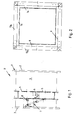
- FIG. 1 shows a basic housing 1, which is composed essentially of three individual parts. A distinction must be made between two frames 2 and 3, which have the same shape and are only dimensionally related. differentiate the depth. Between the two frames 2 and 3 there is a channel part 4, which is described below.
- a dashed flap leaf 5 which is pivotable about an axis of rotation 6 in the direction z. This pivoting can take place by means of an actuating lever mechanism, which is designated overall by 7 and consists of individual parts described below.
- a securing system 8 which is also described further below, serves to fix the actuating lever mechanism 7 or the flap leaf 5 in an open position.
- Each frame 2 or 3 is composed of two L-shaped parts which are then connected to one another in their edge regions, so that an approximately rectangular frame 2 or 3 is formed.
- 9 side strips 10 are folded from frame sheets, which thus form an edge for the frame sheets 9.
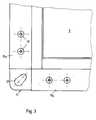
- two adjacent side strips 10a and 10b are deposited at an angle 11, which has a fastening opening 12. This angle 11 is connected to the side strips 10a and 10b via screws 13.
- connection bracket 11 eliminates the need for welding or spot welding to join the individual frame parts. This is one of the advantages of the present invention.
- the assembly of the two frames 2 and 3 after manufacture takes place by means of four U-shaped profiles 14, which are made of a stable sheet metal.
- the Cross section of these profiles 14 can be seen above all in FIG. 4.
- a base leg 15 of the profile forms the boundary of the channel part 4 inwards or faces the flap leaf 5.
- Two side legs 16 and 17 projecting from the base legs 15 have at the end an additional folding strip 18 which is folded back and which, in the position of use, each comprises a side strip 10 of the frame 2 or 3.
- the folded strips 18, side strips 10 and possibly side legs 16 and 17 are connected in a form-fitting manner by corresponding crimp connections 19.
- part of the folded strip 18 is pressed into the side strip 10 or is pressed out together with a corresponding part of the side strip 10.
- There are special crib machines for this purpose so that no welding is necessary even when assembling the entire basic housing 1. Entire extraction devices with extraction fans or the like, which are normally necessary for zinc welding processes, can be omitted.
- Each profile 14 engages about 10-30 mm in the clear width of the basic housing 1 formed by the frame leaves 9 and rotates around the flap leaf 5 in the position of use. Since the U-shaped profile is otherwise open to the outside, it can be mortar 20 or other material are poured out. This prevents direct transmission of fire. For example, the fire can only penetrate between the side strips 10 and the side legs 17 when it hits the side leg 17 and is then passed through the folded strip 18 into the mortar. There is no transition to the other side.
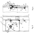
- FIGS. 5 and 6 no longer have any connection with the axis of rotation 6 of the flap leaf 5.
- the actuating lever mechanism 7 is connected to the flap leaf 5 by means of a fastening bracket 21. 6, a stop 22 can also be seen on the fastening bracket 21, which prevents the flap leaf 5 from falling through, since the stop 22 abuts a profile 14 in the closed position of the flap leaf 5.
- a lever 23 is connected to the mounting bracket 21 via an axis of rotation 24. At the other end, this lever 23 also forms a swivel joint 26 with a second lever 25. This lever 25 is firmly connected to an adjusting lever 27 which rotates about an axis of rotation 28. The actuating lever 27 is under the pressure of a helical spring 29, this helical spring 29 holding the actuating lever 27 in the position shown in FIG. 5. If the adjusting lever 27 is pivoted along the dash-dotted line 30, the lever 25 bends out of the aligned position with the lever 23, both rotating about the swivel joint 26. As a result, a pull is exerted on the fastening bracket 21 or the flap leaf 5 and this is pivoted out of the firing position into an open position. This continues until the flap leaf 5 strikes a stop pin 31.
- the stop pin 31 passes through an angle strip 32 and a nut 33 attached to it, so that its length, which is excellent from the angle strip 32, can be changed. This allows the stop to be adjusted.
- the setting is such that when the flap leaf 5 strikes the stop bolt 31, the actuating lever 27 has reached the securing device 8 and can be fixed there.
- the securing device 8 consists of a pin 34 which is surrounded by a helical spring 35. These Coil spring 35 is supported between a frame sheet 9 and a tab 36, this tab 36 being connected to the frame sheet 9 via a securing plate 37. In this way, the tab 36 is under the pressure of the helical spring 35, the pin 34 of the helical spring 35 on the other hand protruding from the frame sheet 9 and being able to move into a sleeve 38 of the actuating lever 27 in a position of use. As a result, the actuating lever 27 is fixed on the securing device 8.
- the fuse plate 37 which is made of an appropriate material, melts, thus releasing the tab 36 so that the coil spring 35 can relax.
- the pin 34 is pulled out of the sleeve 38, so that the adjusting lever 27 is released, which falls back into its initial position shown in FIG. 5 under the pressure of the coil spring 29.
- the flap leaf 5 is also guided in the closed position, in which the two levers 23 and 25 are aligned with one another. A further rotation of the control lever 27 is prevented by a stop strip 39 near the joint 26.
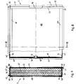
- a sheet is folded so that a continuous rear wall 40, as well as a bottom wall 41 and an upper wall 42 are formed. From top wall 42 and bottom wall 41, two cover strips 43 and 44 are also folded. In the space thus formed between the bottom wall 41 and the top wall 42, two gypsum boards 45 and 46 with insulating material 47 in between can now be used. The end is an inserted front wall 48 made of sheet steel.
- a U-profile 41 is now pushed in and pushed in from the two sides, respectively, with corresponding upper and lower brackets 50 and 51 underlaying the upper wall 42 or standing on the bottom wall 41.
- the side profile 52 laterally overlaps the front wall 48.
- a U-profile strip 56 which is pushed onto the U-profile 49, also serves to fix the bearing sleeve 53.
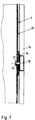
- cover profiles 57 are provided all around the flap leaf, all of which are of similar design.
- the cover profile 57 in turn consists of a sheet metal strip, from which a fastening leg 58 is folded on one side. This mounting leg is by pop rivets, screws or the like. fixed to the rear wall 40 or the cover strip 44. This also causes the front wall 48 to be fixed at the same time.
- an oblique strip 60 is folded from a cover strip 59, from which in turn a folded strip, not shown, is folded over.
- a rubber strip 61 is clamped between this oblique strip 60 or folded strip and held in this way.
- the oblique strip 60 also has the function that it does not cover a material 62 which foams up in the event of fire, but avoids pressing or crumbling out of this foaming material in the event of a fire. In this way, the fire can freely penetrate under the diagonal stripe 60 to the foaming material and heat it as quickly as possible and thereby cause it to foam.
- the oblique strip 60 has the effect that the foaming material 62 is protected against the first fire jet, for example in the event of a fire attempt, and only foams at a desired time.
Landscapes
- Engineering & Computer Science (AREA)
- Chemical & Material Sciences (AREA)
- Combustion & Propulsion (AREA)
- Mechanical Engineering (AREA)
- General Engineering & Computer Science (AREA)
- Health & Medical Sciences (AREA)
- Public Health (AREA)
- Business, Economics & Management (AREA)
- Emergency Management (AREA)
- Air-Flow Control Members (AREA)
- Building Environments (AREA)
Applications Claiming Priority (2)
| Application Number | Priority Date | Filing Date | Title |
|---|---|---|---|
| DE19914114296 DE4114296A1 (de) | 1991-05-02 | 1991-05-02 | Brandschutzklappe |
| DE4114296 | 1991-05-02 |
Publications (2)
| Publication Number | Publication Date |
|---|---|
| EP0512414A2 true EP0512414A2 (fr) | 1992-11-11 |
| EP0512414A3 EP0512414A3 (en) | 1993-08-18 |
Family
ID=6430800
Family Applications (1)
| Application Number | Title | Priority Date | Filing Date |
|---|---|---|---|
| EP19920107390 Withdrawn EP0512414A3 (en) | 1991-05-02 | 1992-04-30 | Fire protection damper |
Country Status (2)
| Country | Link |
|---|---|
| EP (1) | EP0512414A3 (fr) |
| DE (1) | DE4114296A1 (fr) |
Cited By (16)
| Publication number | Priority date | Publication date | Assignee | Title |
|---|---|---|---|---|
| FR2753104A1 (fr) * | 1996-09-11 | 1998-03-13 | Aldes Aeraulique | Systeme d'etancheite pour dispositif d'obturation d'un conduit de ventilation, notamment pour clapet coupe-feu ou trappe de desenfumage |
| DE19649126A1 (de) * | 1996-11-27 | 1998-05-28 | Schako Metallwarenfabrik | Absperrvorrichtung gegen eine Brandübertragung |
| EP0884070A3 (fr) * | 1997-06-09 | 2000-01-19 | Kvaerner Masa-Yards Oy | Dispositif de connexion et de fixation |
| RU2159394C1 (ru) * | 1999-02-19 | 2000-11-20 | Арендное предприятие Головной проектный институт "Челябинскгражданпроект" | Устройство дымоудаления |
| RU2174026C1 (ru) * | 2000-07-03 | 2001-09-27 | Ковалев Иван Григорьевич | Противопожарный клапан для воздуховодов |
| RU2199062C2 (ru) * | 2001-04-05 | 2003-02-20 | Общество с ограниченной ответственностью предприятие "Луч+" | Устройство дымоудаления |
| RU2208745C2 (ru) * | 2001-02-05 | 2003-07-20 | ООО Фирма "Уралсистемсервис" | Устройство дымоудаления |
| ES2232279A1 (es) * | 2003-04-25 | 2005-05-16 | Shako Metallwarenfabrik Ferdinand Schad Kg | Compuerta cortafuegos para conductos de ventilacion y aire acondicionado. |
| RU2343354C1 (ru) * | 2007-06-29 | 2009-01-10 | Государственное образовательное учреждение высшего профессионального образования "Южно-Уральский государственный университет" | Устройство дымоудаления |
| AT512394B1 (de) * | 2012-03-15 | 2013-08-15 | Siegfried Geldner | Absperrvorrichtung zum Verschließen eines Strömungskanals |
| AT512666A1 (de) * | 2012-03-15 | 2013-10-15 | Geldner | Absperrvorrichtung zum Verschließen eines Strömungskanals |
| EP2741022A1 (fr) * | 2012-12-04 | 2014-06-11 | Rf-Technologies nv | Amortisseur d'évacuation de fumée comprenant une pièce de matériau intumescent |
| DE102014103253A1 (de) * | 2014-03-11 | 2015-09-17 | Pta Solutions Gmbh | Feuerwiderstandskörper und Verfahren zur Herstellung desselben |
| EP2988040A1 (fr) * | 2014-08-20 | 2016-02-24 | JKF Industri A/S | Soupape de sûreté et agencement de sécurité pour système de conduites de fluide |
| EP2995353A1 (fr) * | 2014-09-12 | 2016-03-16 | Werner Wildeboer | Installation de desenfumage et de protection contre les incendies pour installations de ventilation, comprenant au moins un element de blocage |
| DE102014113879A1 (de) * | 2014-09-25 | 2016-03-31 | Areva Gmbh | Brandschutzklappenvorrichtung und Verfahren zur Installation einer derartigen Brandschutzklappenvorrichtung in einer Stützstruktur im Erstbeton |
Families Citing this family (4)
| Publication number | Priority date | Publication date | Assignee | Title |
|---|---|---|---|---|
| DE29907688U1 (de) | 1999-04-30 | 1999-10-07 | Hautec Systemelemente GmbH, 01558 Großenhain | Verschluß für großflächige Wand- oder Deckendurchbrüche |
| DE10214243C1 (de) * | 2002-03-26 | 2003-11-27 | Werner Wildeboer | Brandschutzklappe |
| DE50310326D1 (de) | 2003-10-06 | 2008-09-25 | Thomas Kolb | Brandschutz-Verschluss |
| DE202024102987U1 (de) | 2024-06-06 | 2025-09-09 | Wildeboer Bauteile Gmbh | Brandschutztechnische Einrichtung mit einer Brandschutzklappe |
Family Cites Families (6)
| Publication number | Priority date | Publication date | Assignee | Title |
|---|---|---|---|---|
| ZA728732B (en) * | 1971-12-21 | 1973-10-31 | Trox Gmbh Geb | Fire-protection flap valves |
| DE2352830A1 (de) * | 1973-10-20 | 1975-04-30 | Nordluft Norddeutsche Ges Fuer | Absperrvorrichtung gegen feuer und rauch in lueftungs- und/oder heizungsleitungen |
| DE2622147C2 (de) * | 1976-05-19 | 1981-12-17 | Schako Metallwarenfabrik Ferdinand Schad Kg, 7201 Kolbingen | Feuerschutzeinrichtung für Luftkanäle |
| CH643912A5 (de) * | 1979-12-05 | 1984-06-29 | Hesco Pilgersteg Ag | Brandschutzklappe. |
| EP0300992B1 (fr) * | 1987-07-23 | 1992-12-23 | LEOPOLD AUMAYR GESELLSCHAFT M.B.H. & CO. KG | Appareil de protection contre le feu pour conduits de ventilation |
| DE9003159U1 (de) * | 1990-03-17 | 1990-06-28 | "Schako" Metallwarenfabrik Ferdinand Schad KG Zweigniederlassung Kolbingen, 7201 Kolbingen | Brandschutzklappe |
-
1991
- 1991-05-02 DE DE19914114296 patent/DE4114296A1/de not_active Withdrawn
-
1992
- 1992-04-30 EP EP19920107390 patent/EP0512414A3/de not_active Withdrawn
Cited By (22)
| Publication number | Priority date | Publication date | Assignee | Title |
|---|---|---|---|---|
| FR2753104A1 (fr) * | 1996-09-11 | 1998-03-13 | Aldes Aeraulique | Systeme d'etancheite pour dispositif d'obturation d'un conduit de ventilation, notamment pour clapet coupe-feu ou trappe de desenfumage |
| EP0829689A1 (fr) * | 1996-09-11 | 1998-03-18 | Aldes Aeraulique | Système d'étanchéité pour dispositif d'obturation d'un conduit de ventilation, notamment pour clapet coupe-feu ou trappe de désenfumage |
| DE19649126A1 (de) * | 1996-11-27 | 1998-05-28 | Schako Metallwarenfabrik | Absperrvorrichtung gegen eine Brandübertragung |
| DE19649126C2 (de) * | 1996-11-27 | 1998-10-29 | Schako Metallwarenfabrik | Absperrvorrichtung gegen eine Brandübertragung |
| EP0884070A3 (fr) * | 1997-06-09 | 2000-01-19 | Kvaerner Masa-Yards Oy | Dispositif de connexion et de fixation |
| RU2159394C1 (ru) * | 1999-02-19 | 2000-11-20 | Арендное предприятие Головной проектный институт "Челябинскгражданпроект" | Устройство дымоудаления |
| RU2174026C1 (ru) * | 2000-07-03 | 2001-09-27 | Ковалев Иван Григорьевич | Противопожарный клапан для воздуховодов |
| RU2208745C2 (ru) * | 2001-02-05 | 2003-07-20 | ООО Фирма "Уралсистемсервис" | Устройство дымоудаления |
| RU2199062C2 (ru) * | 2001-04-05 | 2003-02-20 | Общество с ограниченной ответственностью предприятие "Луч+" | Устройство дымоудаления |
| ES2232279B1 (es) * | 2003-04-25 | 2006-08-01 | Shako Metallwarenfabrik Ferdinand Schad Kg | Compuerta cortafuegos para conductos de ventilacion y aire acondicionado. |
| ES2232279A1 (es) * | 2003-04-25 | 2005-05-16 | Shako Metallwarenfabrik Ferdinand Schad Kg | Compuerta cortafuegos para conductos de ventilacion y aire acondicionado. |
| RU2343354C1 (ru) * | 2007-06-29 | 2009-01-10 | Государственное образовательное учреждение высшего профессионального образования "Южно-Уральский государственный университет" | Устройство дымоудаления |
| AT512394B1 (de) * | 2012-03-15 | 2013-08-15 | Siegfried Geldner | Absperrvorrichtung zum Verschließen eines Strömungskanals |
| AT512394A4 (de) * | 2012-03-15 | 2013-08-15 | Geldner | Absperrvorrichtung zum Verschließen eines Strömungskanals |
| EP2642167A3 (fr) * | 2012-03-15 | 2013-10-09 | Siegfried Geldner | Dispositif de fermeture pour fermer un canal d'écoulement |
| AT512666A1 (de) * | 2012-03-15 | 2013-10-15 | Geldner | Absperrvorrichtung zum Verschließen eines Strömungskanals |
| AT512666B1 (de) * | 2012-03-15 | 2014-02-15 | Siegfried Geldner | Absperrvorrichtung zum Verschließen eines Strömungskanals |
| EP2741022A1 (fr) * | 2012-12-04 | 2014-06-11 | Rf-Technologies nv | Amortisseur d'évacuation de fumée comprenant une pièce de matériau intumescent |
| DE102014103253A1 (de) * | 2014-03-11 | 2015-09-17 | Pta Solutions Gmbh | Feuerwiderstandskörper und Verfahren zur Herstellung desselben |
| EP2988040A1 (fr) * | 2014-08-20 | 2016-02-24 | JKF Industri A/S | Soupape de sûreté et agencement de sécurité pour système de conduites de fluide |
| EP2995353A1 (fr) * | 2014-09-12 | 2016-03-16 | Werner Wildeboer | Installation de desenfumage et de protection contre les incendies pour installations de ventilation, comprenant au moins un element de blocage |
| DE102014113879A1 (de) * | 2014-09-25 | 2016-03-31 | Areva Gmbh | Brandschutzklappenvorrichtung und Verfahren zur Installation einer derartigen Brandschutzklappenvorrichtung in einer Stützstruktur im Erstbeton |
Also Published As
| Publication number | Publication date |
|---|---|
| EP0512414A3 (en) | 1993-08-18 |
| DE4114296A1 (de) | 1992-11-05 |
Similar Documents
| Publication | Publication Date | Title |
|---|---|---|
| DE4114296A1 (de) | Brandschutzklappe | |
| DE19600369C2 (de) | Brandschutzeinrichtung zur Abschottung einer Rohrleitung | |
| DE2952031C2 (de) | Halterung zum Tragen der Kopfschiene einer Lamellenjalousie | |
| DE2103966A1 (de) | Luftkammerkonstruktion | |
| EP1516996A2 (fr) | Fenêtre résistant aux explosions | |
| DE10134839A1 (de) | Einrichtung zum rauch- und feuerbeständigen Verschliessen eines Wand- oder Deckendurchbruchs | |
| EP0447944A1 (fr) | Volet coupe-feu | |
| EP0824940A2 (fr) | Clapet coupe-feu | |
| DE2360285C3 (de) | Lüftungs- und Druckentlastungsvorrichtung für Schaltanlagen | |
| DE9106220U1 (de) | Brandschutzklappe | |
| DE9003159U1 (de) | Brandschutzklappe | |
| DE2625270A1 (de) | Falttor | |
| WO2009006970A1 (fr) | Élément de recouvrement pour opérations de maintenance | |
| EP0454879B1 (fr) | Appareil de ventilation pour installation de ventilation individuelle | |
| DE3140043C2 (de) | Brandschutzklappe | |
| DE8808393U1 (de) | Vorrichtung zum automatischen Verschließen eines Rohres | |
| EP3492684A1 (fr) | Bascule de déclenchement pour un dispositif d'étanchéité d'une porte pivotante | |
| DE2622147C2 (de) | Feuerschutzeinrichtung für Luftkanäle | |
| DE20109549U1 (de) | Tischtennisplatte | |
| DE29610784U1 (de) | Halterung, wie Standkonsole für mit Konvektorblechen versehene ein- oder mehrlagige Plattenheizkörper | |
| DE2815515A1 (de) | Vorrichtung zum abdichten und schliessen von feuerschutzabschluessen fuer oeffnungen in waenden und decken bei durch transportanlagen verbundenen raeumen | |
| DE29614941U1 (de) | Brandschutzeinrichtung für eine Lüftungsrohrleitung | |
| DE2555029A1 (de) | Feuerschutzeinrichtung fuer luftkanaele | |
| EP1344890A2 (fr) | Cadre de porte protégé contre le feu dans un local de securité protégé contre le feu | |
| EP4279146A1 (fr) | Clapet coupe-feu |
Legal Events
| Date | Code | Title | Description |
|---|---|---|---|
| PUAI | Public reference made under article 153(3) epc to a published international application that has entered the european phase |
Free format text: ORIGINAL CODE: 0009012 |
|
| AK | Designated contracting states |
Kind code of ref document: A2 Designated state(s): AT BE CH DE DK ES FR GB GR IT LI LU MC NL PT SE |
|
| RBV | Designated contracting states (corrected) |
Designated state(s): AT BE CH DE DK ES FR GB GR IT LI LU NL PT SE |
|
| PUAL | Search report despatched |
Free format text: ORIGINAL CODE: 0009013 |
|
| AK | Designated contracting states |
Kind code of ref document: A3 Designated state(s): AT BE CH DE DK ES FR GB GR IT LI LU MC NL PT SE |
|
| 17P | Request for examination filed |
Effective date: 19931008 |
|
| 17Q | First examination report despatched |
Effective date: 19950505 |
|
| STAA | Information on the status of an ep patent application or granted ep patent |
Free format text: STATUS: THE APPLICATION IS DEEMED TO BE WITHDRAWN |
|
| 18D | Application deemed to be withdrawn |
Effective date: 19950916 |