EP1344890A2 - Cadre de porte protégé contre le feu dans un local de securité protégé contre le feu - Google Patents
Cadre de porte protégé contre le feu dans un local de securité protégé contre le feu Download PDFInfo
- Publication number
- EP1344890A2 EP1344890A2 EP03001904A EP03001904A EP1344890A2 EP 1344890 A2 EP1344890 A2 EP 1344890A2 EP 03001904 A EP03001904 A EP 03001904A EP 03001904 A EP03001904 A EP 03001904A EP 1344890 A2 EP1344890 A2 EP 1344890A2
- Authority
- EP
- European Patent Office
- Prior art keywords
- leg
- side wall
- door
- wall element
- fire
- Prior art date
- Legal status (The legal status is an assumption and is not a legal conclusion. Google has not performed a legal analysis and makes no representation as to the accuracy of the status listed.)
- Withdrawn
Links
Images




Classifications
-
- E—FIXED CONSTRUCTIONS
- E06—DOORS, WINDOWS, SHUTTERS, OR ROLLER BLINDS IN GENERAL; LADDERS
- E06B—FIXED OR MOVABLE CLOSURES FOR OPENINGS IN BUILDINGS, VEHICLES, FENCES OR LIKE ENCLOSURES IN GENERAL, e.g. DOORS, WINDOWS, BLINDS, GATES
- E06B5/00—Doors, windows, or like closures for special purposes; Border constructions therefor
- E06B5/10—Doors, windows, or like closures for special purposes; Border constructions therefor for protection against air-raid or other war-like action; for other protective purposes
- E06B5/16—Fireproof doors or similar closures; Adaptations of fixed constructions therefor
- E06B5/161—Profile members therefor
-
- E—FIXED CONSTRUCTIONS
- E06—DOORS, WINDOWS, SHUTTERS, OR ROLLER BLINDS IN GENERAL; LADDERS
- E06B—FIXED OR MOVABLE CLOSURES FOR OPENINGS IN BUILDINGS, VEHICLES, FENCES OR LIKE ENCLOSURES IN GENERAL, e.g. DOORS, WINDOWS, BLINDS, GATES
- E06B1/00—Border constructions of openings in walls, floors, or ceilings; Frames to be rigidly mounted in such openings
- E06B1/56—Fastening frames to the border of openings or to similar contiguous frames
- E06B1/60—Fastening frames to the border of openings or to similar contiguous frames by mechanical means, e.g. anchoring means
-
- E—FIXED CONSTRUCTIONS
- E06—DOORS, WINDOWS, SHUTTERS, OR ROLLER BLINDS IN GENERAL; LADDERS
- E06B—FIXED OR MOVABLE CLOSURES FOR OPENINGS IN BUILDINGS, VEHICLES, FENCES OR LIKE ENCLOSURES IN GENERAL, e.g. DOORS, WINDOWS, BLINDS, GATES
- E06B5/00—Doors, windows, or like closures for special purposes; Border constructions therefor
- E06B5/10—Doors, windows, or like closures for special purposes; Border constructions therefor for protection against air-raid or other war-like action; for other protective purposes
- E06B5/16—Fireproof doors or similar closures; Adaptations of fixed constructions therefor
-
- E—FIXED CONSTRUCTIONS
- E06—DOORS, WINDOWS, SHUTTERS, OR ROLLER BLINDS IN GENERAL; LADDERS
- E06B—FIXED OR MOVABLE CLOSURES FOR OPENINGS IN BUILDINGS, VEHICLES, FENCES OR LIKE ENCLOSURES IN GENERAL, e.g. DOORS, WINDOWS, BLINDS, GATES
- E06B1/00—Border constructions of openings in walls, floors, or ceilings; Frames to be rigidly mounted in such openings
- E06B1/70—Sills; Thresholds
Definitions
- the invention relates to a fire-protected security room for information technology Facilities with fire-proof side wall elements having side walls, in which by means of a door frame with a Sealing arrangement a door is installed, with a floor and a ceiling.
- Such a fire protection security room is specified in WO 00/29685.
- the side walls are modular fire-proof side wall elements executed and point between the side wall elements are surrounded by a door frame or door frame Door opening with a fitted in it and with a fire-proof one Seal arrangement surrounding door.
- the security room is at the top with fire-proof ceiling elements and down with one fire-proof floor completed. Fire safety To ensure that the door area comes in particular Meaning too.
- the invention has for its object a security room at the beginning to provide the type mentioned, in which the door area in particular is high Fire safety requirements are sufficient.
- a stable, fire-proof construction results from the fact that the Outer sheathing on their facing the adjacent side wall element Side is provided with a right-angled receptacle, with a Butt leg of an associated narrow side of the side wall element and a Contact leg of the flat outside of the side wall element under each Intermediate layer of a fire-proof sealing element are facing.
- a favorable training for the stable assembly consists in the fact that one to the Butt joint adjoining inner leg of the outer casing parallel to the inside of the side wall element is aligned with it, that the inside of the sidewall element and the inner leg are close to that between the bumper leg and the associated narrow side of the side wall element formed gap with clamping means of the tensioning device are provided, which are pressed together by means of a clamping element of the sealing element lying in the joint gap can be braced against one another are, and that with an anchoring unit of the tensioning device the contact leg by pressing the assigned Sealing element against the outside of the side wall element is braced.
- Anchor rail is attached, at least in sections at least a slit-shaped opening facing the interior and a boundary that delimits it which is directed away from the bumper leg, which from an adapted, bent parallel gripping edge of the clamping element is gripped that the clamping element with its opposite, likewise bent further gripping edge attached to the side wall element Engages behind clamping means on an opposite bent edge, the further gripping edge and the bent edge of the clamping means are directed obliquely upwards to the bumper leg, and that in the at least a slot-shaped opening of the anchor rail or on one this attached thread is held an anchor screw with which one hand on the inside of the wall element and on the other hand on the opening side the anchor rail-supported holding piece can be clamped.
- connection can be supported in that the clamping means as along the butt gap V-shaped upwards tapering clamp hooks and that respective clamping element are designed as a slide wedge and that the anchoring unit is insertable into the gap from the inside of the room Has hook element that by means of one on the inside of the room pointing thread section turned on an attached, the butt gap bridging retaining plate adjacent screw nut in a hook receptacle of the door frame or the side wall element hooked section is braced.
- the measures are to cover and cover the connection points advantageous that the outer casing on its inside one of the Has inner legs parallel to the interior staggered inner section and that the shock gap with the tensioning device by means of a shock gap hollow cover strip is covered, which at most to the interior of the room protrudes toward the inner portion.
- a simple and reliable assembly is still achieved in that at least the sealant introduced into the gap as a sealing unit with integrated foaming section and / or moisture sealing section is trained.
- the side of the casing surrounding the door opening is set off three times at right angles in such a way that there are two in cross section Interior angles result, with the door frame increasingly towards the interior the door opening comes forward and runs parallel to the wall and door surface Stop surfaces and the outer stop surface from the outer portion the casing is formed.
- the measures also contribute to reliable, fire-proof sealing that the door adapted to the circumference of the stop surfaces Has counter stop surfaces and that between all stop surfaces and Counterstop fire protection seals and at least between the outer or inner stop surface and the associated counter stop surface with regard to the outside of the gap in front of the fire protection seal Moisture seal is arranged.
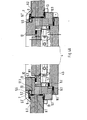
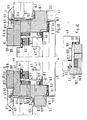
- FIG. 1A and 1B show a side wall area of a fire protection room with individual side wall elements 1, a door frame 3, one arranged above the upper part wall element 2 'and a lower part wall element 2, both in the width of the door frame 3, and one in the opening of the door frame 3 to be used door 4.
- the side wall can be used with these Build up elements in a modular way, whereby between the individual elements fire-proof sealants and the adjoining Elements stably held together using easy-to-install bracing elements become.
- the security room is made up of several side walls, one from individual ceiling elements modular ceiling and a floor composed of several floor elements, such as in the publication WO 00/29685 mentioned in the introduction.
- the door frame 3 consists of two vertical legs 3.1, 3.2, an upper one Horizontal leg 3.3 and a lower horizontal leg 3.4, the the two vertical legs 3.1, 3.2 and the upper horizontal leg 3.3 are the same Have cross-section, as shown in Figures 3A, 3B, 4A and 5.
- hinge elements 3.5 are arranged in the match the hinge parts 4.1 of the door 4 that are matched to this with the door hung.
- On the side of the door frame 3 surrounding the clear door opening is in the vertical legs 3.1, 3.2 and the upper horizontal leg 3.3 a circumferential groove-like recess 3.6 formed in the locking bolt 4.2 the door 4 intervene for stable locking.
- the vertical legs 3.1, 3.2 and the upper and the lower horizontal leg 3.3, 3.4 of the door frame 3 each have an outer casing 12 appropriately shaped metal, especially sheet steel, the fire protection material 10 with several fire protection layers 10.1 to 10.6 with one another encompasses coordinated properties.
- the two vertical frame legs 3.1, 3.2 and the upper horizontal leg 3.3 have the same cross section, 3A, 3B, 4A, 4B and 5A and 5B.
- the sealing unit 8.1 can also have yet another external moisture seal that is part of the Sealing package is introduced or as a separate element in this area can be.
- the sealing means 8 can be designed accordingly or, as shown in FIGS. 4A, 4B and 5A, 5B, as a simplified sealing part 8.2 be designed with a fire protection seal.
- the anchoring unit 5 includes, as shown in FIGS. 1A, 4A and 5A, one on the door frame 3 on the adjacent, opposite the parallel inside of the side wall element 1 recessed inner leg 12.3 on the casing 12 attached, e.g. B. C-shaped anchor rail 20 with its slot-shaped Opening to the inside of the security room is turned.
- the slot-shaped opening of the anchor rail 20 uses an anchor screw 5.5, with its square head the edges of the slot-shaped on both sides Engages behind the opening and with its shaft projecting towards the interior of the room Raised through the holding plate (5.2) on the opening side of the anchor rail and on the adjacent inner wall area of the wall element 1 is supported if a nut screwed onto the shaft is tightened.
- the anchoring unit 5 alternatively comprises or additionally a hook element 5.1 with a hook section and one during installation threaded section or threaded bolt facing inside the room 5.4 and nuts 5.3.
- the hook element 5.1 is used for anchoring with his Hook part in a matching recess in the bumper leg 12.1 the casing 12 is hooked in and stands with the threaded section or threaded bolts 5.4 on the inside of the room over the flat inner wall surface of the side wall element 1 and a parallel and thus aligned, inner leg bent at right angles from the bumper leg 12.1 12.3 of the outer casing 12 and protrudes through the mounting plate 5.2, located on the inner leg 12.3 and the inside of the side wall element 1 supports the gap by bridging.
- the door frame 3 is braced with the side wall element 1, the System leg 12.2 compresses the corresponding sealing part 8.2.
- the clamping unit 6 is also used to the shock leg 12.1 Outer casing 12 against the narrow side of the adjacent side wall element 1 to brace.
- the clamping unit 6 points to the side wall element 1 near the butt gap a clamp hook 6.2 and the Inner leg 12.3 also in the vicinity of the butt gap a clamping hook 6.2 on, wherein the two clamping hooks are arranged in a V-shape to each other and taper upwards.
- the clamping unit 6 is shown in more detail in the mentioned publication WO 00/29685 and also serves for connecting the wall elements.
- the outer casing 12 continues to have an inner section 12.4 provided, opposite the inner leg 12.3 to the interior of the room is offset in parallel.
- the connection point between the side wall element 1 and the door frame 3 in the area of the butt gap is by means of a cover strip 7 which is hollow towards the joint gap and which does not have the inner section 12.4 protrudes into the interior, so that a non-distracting conclusion the liaison is obtained.
- the outer sheathing of the door frame 3 goes with the vertical legs under consideration 3.1, 3.2 and the upper horizontal leg 3.3 the contact leg 12.2 with a right-angled bend in one Section directed perpendicular to the wall surface of the side wall element 1 and then into one parallel to the wall surface of the side wall element 1 directional section over which an outer stop surface of the door frame 3 forms for the door 4 with a corresponding counter stop surface.
- On your the side facing the door opening has the two vertical legs 3.1, 3.2 and the upper horizontal leg 2.3 two further stop surfaces, namely a middle stop surface 12.6 and an inner stop surface 12.7, between which are each perpendicular to the wall surface of the side wall element 1 extending sections are present, including the inner stop surface 12.7 passes over a vertical section into the inner section 12.4.
- the door 4 has counter-stop surfaces adapted to the stop surfaces 12.5, 12.6, 12.7 on. Between the three stop surfaces 12.5, 12.6, 12.7 and the associated counter-stop surfaces of door 4 are fire protection seals 9.2 arranged. Complementary is between the outer and the inner Stop surface 12.5, 12.7 each towards the open side of the gap Moisture seal 9.1 arranged. At least in the vertical range Section between the outer stop surface 12.5 and the middle stop surface 12.6 is between the adjacent edge of the door 4 and the vertical section additionally a foam seal 9.3 is provided, the in the event of great heat in the event of a fire, foams up so that it warps opening additional gaps are securely closed and a Prevention of fire gas over a specified time (e.g. 90 minutes) prevented becomes. This can also be done on the other vertical sections Foam seal 9.3 may be provided. In the middle vertical section between the middle stop surface 12.6 and the inner stop surface 12.7 is the already mentioned groove-like depression 3.6.
- the lower horizontal leg 3.4 is essentially angular in the present case also built with an outer jacket that has several fire protection layers 10.7 to 10.9 encloses of fire protection material, as Fig. 4B shows.
- the angle is the inside angle on the side of the door facing the door opening lower horizontal leg 3.4 formed, resulting in the to the wall surface parallel outer side of the lower horizontal leg 2.4 an outer Stop surface and an inner stop surface on the parallel angle leg result with the outer or inner stop surface 12.5, 12.7 of the other door frame legs 3.1, 3.2, 3.3 lie in one plane and with corresponding counter stop surfaces of the door 4 cooperate.
- a sealing arrangement here 9 with moisture seals 9.1 and at least one fire protection seal 9.2 provided the moisture seals 9.1 with respect the fire protection seal 9.2 on the outer side of the to be sealed Gap are arranged.
- a foam seal 9.3 On the section perpendicular to the wall surface between the contact surfaces is also a foam seal 9.3 corresponding effect as with the other door frame legs 3.1, 3.2, 3.3 arranged.
- the door provided with a door closer 11 (see FIGS. 3B and 5) points to it Inside 4.4 and its outside 4.5 an easy-to-use handle 4.3 'or 4.3, while facing the door frame 3 Narrow sides 4.6 with the counter abutment surfaces mentioned and in between vertical sections is provided.
- a locking mechanism 40 with a vertical side and horizontal bolt supports 4.7, 4.7 ', 4.7 "operated, the upper Bolt support 4.7 "by means of a spring arrangement with spring elements 4.8 for compliance an upper locking position can be applied.
- door signaling contacts 4.9 provided that cooperate with a monitoring device.
Landscapes
- Engineering & Computer Science (AREA)
- Civil Engineering (AREA)
- Structural Engineering (AREA)
- Mechanical Engineering (AREA)
- Door And Window Frames Mounted To Openings (AREA)
- Special Wing (AREA)
Applications Claiming Priority (4)
| Application Number | Priority Date | Filing Date | Title |
|---|---|---|---|
| DE10211242 | 2002-03-13 | ||
| DE10211242 | 2002-03-13 | ||
| DE10240701A DE10240701B4 (de) | 2002-03-13 | 2002-09-04 | Brandgeschützter Sicherheitsraum |
| DE10240701 | 2002-09-04 |
Publications (2)
| Publication Number | Publication Date |
|---|---|
| EP1344890A2 true EP1344890A2 (fr) | 2003-09-17 |
| EP1344890A3 EP1344890A3 (fr) | 2004-02-04 |
Family
ID=27766700
Family Applications (1)
| Application Number | Title | Priority Date | Filing Date |
|---|---|---|---|
| EP03001904A Withdrawn EP1344890A3 (fr) | 2002-03-13 | 2003-01-30 | Cadre de porte protégé contre le feu dans un local de securité protégé contre le feu |
Country Status (1)
| Country | Link |
|---|---|
| EP (1) | EP1344890A3 (fr) |
Cited By (3)
| Publication number | Priority date | Publication date | Assignee | Title |
|---|---|---|---|---|
| DE102008040434A1 (de) * | 2008-07-15 | 2010-01-21 | Sommer Metallbau-Stahlbau Gmbh & Co. Kg | Objektschutztür mit rahmenseitiger Dichtung |
| CN102213067A (zh) * | 2011-05-26 | 2011-10-12 | 中国人民解放军总参谋部工程兵第四设计研究院 | 防火密闭观察窗 |
| CN111959251A (zh) * | 2020-08-14 | 2020-11-20 | 重庆大江智防特种装备有限公司 | 一种大型车辆车门防火密封结构 |
Family Cites Families (5)
| Publication number | Priority date | Publication date | Assignee | Title |
|---|---|---|---|---|
| US2742117A (en) * | 1951-07-30 | 1956-04-17 | Andean Corp | Adjustable door jamb |
| DE2447416A1 (de) * | 1974-10-04 | 1976-04-08 | Heinrich B Schaefers | Tuerzarge mit befestigungs-vorrichtung |
| DE4232312A1 (de) * | 1992-09-26 | 1994-03-31 | Trube & Kings Kg | Feuerhemmendes Bauteil |
| ES2128506T3 (es) * | 1993-10-29 | 1999-05-16 | Polynorm Nv | Tabique resistente al fuego y bastidor para el mismo. |
| DE19852927B4 (de) * | 1998-11-17 | 2004-05-27 | Otto Lampertz Gmbh & Co. Kg | Sicherheitsraum für informationstechnische Einrichtungen |
-
2003
- 2003-01-30 EP EP03001904A patent/EP1344890A3/fr not_active Withdrawn
Cited By (5)
| Publication number | Priority date | Publication date | Assignee | Title |
|---|---|---|---|---|
| DE102008040434A1 (de) * | 2008-07-15 | 2010-01-21 | Sommer Metallbau-Stahlbau Gmbh & Co. Kg | Objektschutztür mit rahmenseitiger Dichtung |
| CN102213067A (zh) * | 2011-05-26 | 2011-10-12 | 中国人民解放军总参谋部工程兵第四设计研究院 | 防火密闭观察窗 |
| CN102213067B (zh) * | 2011-05-26 | 2012-05-23 | 中国人民解放军总参谋部工程兵第四设计研究院 | 防火密闭观察窗 |
| CN111959251A (zh) * | 2020-08-14 | 2020-11-20 | 重庆大江智防特种装备有限公司 | 一种大型车辆车门防火密封结构 |
| CN111959251B (zh) * | 2020-08-14 | 2024-04-09 | 重庆大江智防特种装备有限公司 | 一种大型车辆车门防火密封结构 |
Also Published As
| Publication number | Publication date |
|---|---|
| EP1344890A3 (fr) | 2004-02-04 |
Similar Documents
| Publication | Publication Date | Title |
|---|---|---|
| EP0862873A1 (fr) | Ferrure pour fixation | |
| DE69729138T2 (de) | Sicherheitsverschluss | |
| EP0071184B1 (fr) | Collier de serrage pour tuyaux souples | |
| EP2444562B1 (fr) | Espace de sécurité | |
| DE2910325A1 (de) | Halter fuer schutzgelaender | |
| DE19526725C2 (de) | Abschottvorrichtung zum dichten Verschließen einer Gebäudeöffnung bei Hochwassergefahr | |
| EP2935742A1 (fr) | Système de porte | |
| DE202004002331U1 (de) | Beschlagsystem zum Einbau eines Fensters o.dgl. | |
| EP0539672B1 (fr) | Ferrure pour fixation dans une rainure d'un profilé rétréci des deux côtés | |
| EP1344890A2 (fr) | Cadre de porte protégé contre le feu dans un local de securité protégé contre le feu | |
| DE19719113C2 (de) | Türsystem | |
| EP2171177A1 (fr) | Élément de recouvrement pour opérations de maintenance | |
| DE3214915C2 (fr) | ||
| DE69415634T2 (de) | Feuerbeständige Trennwand und Rahmen dafür | |
| DE10240701B4 (de) | Brandgeschützter Sicherheitsraum | |
| EP0438046A1 (fr) | Pièce d'assemblage d'angle pour dormants | |
| DE19545375C2 (de) | Tür insbesondere Falttür | |
| DE19618043C1 (de) | Unterkonstruktion zum Befestigen von Scharnierlappen an Zargen | |
| DE102021210759B4 (de) | Schutzzaunsystem und Verfahren zum Montieren eines Schutzzaunsystems | |
| EP0057454B1 (fr) | Dispositif de suspension réglable en hauteur | |
| DE3249938C2 (fr) | ||
| AT408784B (de) | Anordnung zum befestigen von im wesentlichen u-förmigen führungsschienen für rolladen sowie baugruppe aus führungsschiene und halteteilen für eine solche anordnung | |
| DE29506177U1 (de) | Bandseitige Türsicherung | |
| DE3617219A1 (de) | Verfahren und vorrichtung zur montage von zwischenwaenden und pfosten | |
| EP1273751B1 (fr) | Cadre pour une porte à un ou plusieurs battants |
Legal Events
| Date | Code | Title | Description |
|---|---|---|---|
| PUAI | Public reference made under article 153(3) epc to a published international application that has entered the european phase |
Free format text: ORIGINAL CODE: 0009012 |
|
| AK | Designated contracting states |
Kind code of ref document: A2 Designated state(s): AT BE BG CH CY CZ DE DK EE ES FI FR GB GR HU IE IT LI LU MC NL PT SE SI SK TR |
|
| AX | Request for extension of the european patent |
Extension state: AL LT LV MK RO |
|
| PUAL | Search report despatched |
Free format text: ORIGINAL CODE: 0009013 |
|
| AK | Designated contracting states |
Kind code of ref document: A3 Designated state(s): AT BE BG CH CY CZ DE DK EE ES FI FR GB GR HU IE IT LI LU MC NL PT SE SI SK TR |
|
| AX | Request for extension of the european patent |
Extension state: AL LT LV MK RO |
|
| RIC1 | Information provided on ipc code assigned before grant |
Ipc: 7E 06B 1/60 B Ipc: 7E 06B 5/16 A |
|
| REG | Reference to a national code |
Ref country code: HK Ref legal event code: DE Ref document number: 1061419 Country of ref document: HK |
|
| 17P | Request for examination filed |
Effective date: 20040804 |
|
| AKX | Designation fees paid |
Designated state(s): AT BE BG CH CY CZ DE DK EE ES FI FR GB GR HU IE IT LI LU MC NL PT SE SI SK TR |
|
| STAA | Information on the status of an ep patent application or granted ep patent |
Free format text: STATUS: THE APPLICATION IS DEEMED TO BE WITHDRAWN |
|
| 18D | Application deemed to be withdrawn |
Effective date: 20050802 |
|
| REG | Reference to a national code |
Ref country code: HK Ref legal event code: WD Ref document number: 1061419 Country of ref document: HK |