EP0514507B1 - Dispositif d'ouverture et de fermeture d'une cartouche de film en feuille - Google Patents
Dispositif d'ouverture et de fermeture d'une cartouche de film en feuille Download PDFInfo
- Publication number
- EP0514507B1 EP0514507B1 EP91919838A EP91919838A EP0514507B1 EP 0514507 B1 EP0514507 B1 EP 0514507B1 EP 91919838 A EP91919838 A EP 91919838A EP 91919838 A EP91919838 A EP 91919838A EP 0514507 B1 EP0514507 B1 EP 0514507B1
- Authority
- EP
- European Patent Office
- Prior art keywords
- cassette
- support element
- biased
- spring
- opening
- Prior art date
- Legal status (The legal status is an assumption and is not a legal conclusion. Google has not performed a legal analysis and makes no representation as to the accuracy of the status listed.)
- Expired - Lifetime
Links
- 230000007246 mechanism Effects 0.000 abstract description 4
- 230000004044 response Effects 0.000 abstract description 2
- 230000001419 dependent effect Effects 0.000 description 2
- 230000000994 depressogenic effect Effects 0.000 description 2
- 230000004048 modification Effects 0.000 description 2
- 238000012986 modification Methods 0.000 description 2
- 230000009471 action Effects 0.000 description 1
- 238000007664 blowing Methods 0.000 description 1
- 238000001514 detection method Methods 0.000 description 1
Images





Classifications
-
- G—PHYSICS
- G03—PHOTOGRAPHY; CINEMATOGRAPHY; ANALOGOUS TECHNIQUES USING WAVES OTHER THAN OPTICAL WAVES; ELECTROGRAPHY; HOLOGRAPHY
- G03B—APPARATUS OR ARRANGEMENTS FOR TAKING PHOTOGRAPHS OR FOR PROJECTING OR VIEWING THEM; APPARATUS OR ARRANGEMENTS EMPLOYING ANALOGOUS TECHNIQUES USING WAVES OTHER THAN OPTICAL WAVES; ACCESSORIES THEREFOR
- G03B42/00—Obtaining records using waves other than optical waves; Visualisation of such records by using optical means
- G03B42/02—Obtaining records using waves other than optical waves; Visualisation of such records by using optical means using X-rays
- G03B42/04—Holders for X-ray films
- G03B42/045—Holders for X-ray films apparatus for loading or unloading the holders
-
- Y—GENERAL TAGGING OF NEW TECHNOLOGICAL DEVELOPMENTS; GENERAL TAGGING OF CROSS-SECTIONAL TECHNOLOGIES SPANNING OVER SEVERAL SECTIONS OF THE IPC; TECHNICAL SUBJECTS COVERED BY FORMER USPC CROSS-REFERENCE ART COLLECTIONS [XRACs] AND DIGESTS
- Y10—TECHNICAL SUBJECTS COVERED BY FORMER USPC
- Y10T—TECHNICAL SUBJECTS COVERED BY FORMER US CLASSIFICATION
- Y10T74/00—Machine element or mechanism
- Y10T74/18—Mechanical movements
- Y10T74/18008—Oscillating to reciprocating and alternating rotary
-
- Y—GENERAL TAGGING OF NEW TECHNOLOGICAL DEVELOPMENTS; GENERAL TAGGING OF CROSS-SECTIONAL TECHNOLOGIES SPANNING OVER SEVERAL SECTIONS OF THE IPC; TECHNICAL SUBJECTS COVERED BY FORMER USPC CROSS-REFERENCE ART COLLECTIONS [XRACs] AND DIGESTS
- Y10—TECHNICAL SUBJECTS COVERED BY FORMER USPC
- Y10T—TECHNICAL SUBJECTS COVERED BY FORMER US CLASSIFICATION
- Y10T74/00—Machine element or mechanism
- Y10T74/18—Mechanical movements
- Y10T74/18016—Oscillating to reciprocating and intermittent rotary
Definitions
- the invention relates to a device for opening and closing a sheet-film cassette with two cassette portions connected by a hinge and a locking member pivotally mounted at the free end of the cassette lid, said device comprising an unlocking member associated with said locking member and spring-biased pressure bolts associated with the area of the locking member and acting vertically on the cassette lid as well as an opening element pivoting the cassette lid into its open position.
- the opening element has the shape of an angular lever which engages below the cassette lid and is pivotably associated with said lid such that it is brought into a functionally useful position in response to the position of the unlocking member and the position of the support element respectively.
- the support element is attached to the free ends of stationarily mounted arms and is moved up and down by a lever gear driven by a motor.
- the unlocking member is provided with a wedge-shaped spring-biased operating element which is movably mounted and has a concave operating surface.
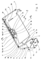
- the device according to the invention forms part of a known unit not illustrated for automatically loading and unloading X-ray sheet film cassettes 1 wherein an exposed sheet film is removed from a cassette 1 and fed to a film processing unit not illustrated whereupon the empty cassette 1 is loaded with another sheet film which has been removed from a supply magazine arranged within the unit.
- the known cassette 1 which is to be handled consists of two cassette portions 1a, 1b which are connected by a hinge 1f and can be locked in their closing position by a locking member 1c.
- the locking member 1c which is pivotally mounted on the cassette lid 1b and spring-biased in the direction of closing engages a locking hook 1d arranged in the lower portion 1a of the cassette, see in particular Fig. 3.
- the cassette portions 1a, 1b are closable in opposition to an inherent bias which causes the cassette portions 1a, 1b to snap open easily when cassette 1 is unlocked.
- lid 1b is provided with a recessed portion 1e which allows the operator to reach below locking member 1c.
- cassette 1 is moved in the direction of the arrow "C" up to an abutment member 30 provided at the end side.
- Lateral alignment elements not illustrated align the cassette 1 in a central position so that the centrally arranged locking member 1c is positioned in the path of movement of an unlocking member 25, 36 to be described further below.
- Sensors not illustrated which are positioned at the end side and laterally of the cassette 1 determine whether cassette 1 has been brought into its intended position and also serve for size detection (sheet film size), the values determined being transferred to a function control device of a type known per se.
- arms 2 and 3 respectively are mounted on either side of the cassette for pivotal movement about stationary bearings 4 and 5 respectively, said arms being connected with each other at their other ends by a support element 6.
- bearings 31, 32 are arranged to which a lever gear each is hinged which comprises two levers 7, 8 and 33, 34 respectively connected with each other by a link 9 and 35 respectively.
- the lever gear 7, 8, 9 and 33, 34, 35 respectively is driven via a driving shaft 10 positively engaging the levers 7 and 33 and driven via a chain-wheel gear 11, 12, 13, shown in dotted lines, by a motor not illustrated which is mounted to a holder 14.
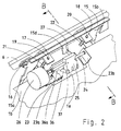
- Support element 6 mounts the means used for unlocking, opening and closing of cassette 1, which will be described below, in particular with reference to Figs. 2, 3 and 5.
- the pressure bolts 19, 20 have enlarged pressure portions 19a and 20a respectively which are associated with the cassette 1.
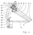
- a mounting plate 23 is biased by pressure springs 21, 22 into contact with the upper side of said pressure portions or - when the device is in its rest position as shown in Fig. 4 - into contact with the inner sides of the lower arms of the U-shaped brackets 17, 18.
- the pressure springs 21, 22 are biased between the arms of the U-shaped brackets 17, 18 and the pressure bolts 19, 20 are held in position by locking washers of a type known per se.
- bent-off portions 23a, 23b are arranged on which a shaft 24 is mounted for rotation about correspondingly designed journals.
- the shaft 24 is driven by a rotary magnet 26 secured to the mounting plate 23.
- an unlocking member 25 which is rigidly connected with shaft 24 and arranged thereon comprises an operating member 36 pivotally mounted about a journal 37 and spring-biased clockwise.
- the operating member 36 is provided with a wedge-shaped and concave operating surface 36a.
- a pawl 27 also pivotally mounted on shaft 24 has a bent-off lug 27a by which the pawl is biased clockwise into contact with the unlocking member 25 by a spring not illustrated.
- the opening element 15 which is pivotable about journals 16 and 29.
- the opening element 15 has two identically shaped check arms 15a, 15b (see Figs. 1 and 2) which are symmetrically aligned with the center of the cassette and spring-biased for movement below cassette lid 1b.
- a control arm 15c which is biased counterclockwise by springs not illustrated and associated with a stationary, inclined ramp 28 is also arranged on opening element 15.
- Support element 6 moreover has a projection 15d which is associated with the pawl 27 of unlocking member 25, 36.
- the device functions as follows: When in its starting position the opening device assumes the upper position (without cassette) illustrated in Figs. 1 and 4. However, in contrast to Figs. 1 and 4, pawl 27 is in its locking position (see Fig. 5) because no unlocking operation has taken place immediately before the upward movement.
- the check arms 15a, 15b of the opening element 15 are thus fixed in a position in which they are pivoted out of the way and inoperative.
- the control device not illustrated After a closed cassette 1 has been fed in in the direction of the arrow "C" and positioned as described at the beginning and the proper position of cassette 1 has been determined the control device not illustrated generates a starting signal which starts the opening device.
- the motor not illustrated is started which drives the driving shaft 10 counterclockwise via the chain-wheel gear 11, 12, 13.
- support element 6 is guided by the arms 2, 3 and lowered via the lever gear 7, 8, 9 and 33, 34, 35 respectively. Its movement is continued until the lower end position of the lever gear 7, 8, 9 and 33, 34, 35 respectively shown in Fig. 5 has been reached in which the motor is stopped by a limit switch not illustrated.
- FIG. 5 shows that when the pressure portions 19a, 20a are placed on cassette 1 the pressure bolts 19, 20 are urged upwards in opposition to the action of the pressure springs 21, 22 whereby the mounting plate 23 is separated from the U-shaped brackets 17, 18 so that it now rests on the pressure portions 19a, 19b of the pressure bolts 19, 20. Due to the spring-bias on the pressure bolts 19, 20 acting on the lid, lid 1b is depressed in opposition to its inherent bias and the closing force of the cassette locking mechanism reduced.
- the rotary magnet 26 is activated which drives the unlocking member 25 with the operating member 36 for clockwise rotation (in Fig. 3 it rotates counterclockwise).
- the wedge-shaped and concave operating surface 36a (see in particular Fig. 3) of operating member 36 is lowered into the recessed portion le of lid 1b to move below the locking member 1c and to pivot said member into the position shown in Fig. 6 in which it is disengaged from the locking hook 1d of the lower portion la (not illustrated) so that cassette 1 is unlocked.
- the range of engagement of the wedge-shaped unlocking member 25, 36 with the recessed portion 1e is very limited and further restricted for tolerance reasons.
- the association according to the invention of the position of the unlocking member 25 and its operating member 36 with the pressure portions 19a, 20a of the pressure bolts 19, 20 ensures that the unlocking member 25 with its operating member 36 is lowered into the recessed portion 1e and engages below the locking member 1c respectively in always the same relationship independently of tolerance variations in the cassette's thickness.
- the unlocking member 25 is provided with a movable operating member 36 which ensures constant engagement with the locking member 1c during unlocking and moreover allows the operating member 36 to move out of the way during entrance into the recessed portion 1e.
- the concave operating surface 36a initially acts on locking member 1c at a flat engagement angle which reduces the force to be exerted during unlocking, and subsequently, after unlocking, assumes a steeper engagement angle to smoothly pivot the locking member 1c into the open position.
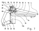
- unlocking the unlocking member 25 positively engages pawl 27 via lug 27a and pivots said pawl away from projection 15d into an inoperative position as shown in Fig. 6 in which the path of movement of the opening element 15 is cleared.
- the lid 1b is first lifted in that the unlocking member 25 and its operating member 36 respectively engage locking member 1c.
- the control arm 15c leaves ramp 28 (see Fig. 8) so that the check arms 15a, 15b are spring-biased to move below lid 1b and automatically adjust themselves to the size-dependent pivotal path of the lid.
- the unlocking member 25, 36 is pivoted counterclockwise by the rotary magnet 26 and returned to its initial position shown in Fig. 9 in which the lid 1b is then moved by the check arms 15a, 15b of the opening element 15 to its final open position as shown in Fig. 4.
- pawl 27 escapes the projection 15d on the opening element 15 in opposition to the spring-bias thereof while remaining in its releasing position.
- a sensor switch not illustrated which is arranged on the mounting plate 23 determines whether the opening element 15 has pivoted a lid 1b into its open position.
- control arm 15c of the opening element 15 once again moves into contact with the ramp 28 and pivots the check arms 15a, 15b clockwise away from cassette 1 so that the cassette can be closed without difficulty.
- the projection 15d of the opening element 15 which also moves back during this operation releases pawl 27 which is now spring-biased into its locking position.
- the spring-biased pressure bolts 19, 19a and 20, 20a urge the lid 1b downwards so that the spring-biased locking member 1c can automatically engage the locking hook 1d of the lower portion 1a so that the cassette 1 is closed and locked.
- the device is brought into its upper starting position as described and shown in Fig. 4.
- the unlocking member 25, 36 remains in its inoperative position shown in Fig. 5 so that pawl 27 also remains operative and by engaging the projection 15d keeps the check arms 15a, 15b of the opening element 15 in the position in which they are pivoted out of the way.
- the loaded cassette 1 is then fed out of the device in opposition to the direction of the arrow "C".
- the last-mentioned operative position of pawl 27 is also maintained if the unlocking member 25, 36 has been unable to open a cassette 1 or if a cassette 1 could not be closed. This ensures that the sequence of functions of the device is not disturbed even if the cassette does not function properly.
Landscapes
- Physics & Mathematics (AREA)
- General Physics & Mathematics (AREA)
- Sheets, Magazines, And Separation Thereof (AREA)
- Radiography Using Non-Light Waves (AREA)
- Semiconductor Memories (AREA)
- Basic Packing Technique (AREA)
- Replacement Of Web Rolls (AREA)
Claims (6)
- Appareil d'ouverture et de fermeture d'une cassette de films en feuille, la cassette ayant deux parties (1a, 1b) de cassette raccordées par une articulation (1f) et un organe de blocage (1c) monté de manière pivotante à l'extrémité libre (1e) de l'une des parties de cassette constituant un couvercle (1b) de la cassette, l'appareil comprenant un organe de déblocage (25, 36) destiné à être au contact de l'organe de blocage (1c), et des pênes de pression (19, 20) sollicités par des ressorts et destinés à agir perpendiculairement vers le couvercle de la cassette dans la région de l'organe de blocage (1c) et un élément d'ouverture (15) destiné à faire pivoter le couvercle de cassette (1b) dans sa position d'ouverture, caractérisé en ce que :- l'organe de déblocage (25, 36) et un élément d'entraînement (26) de celui-ci sont placés sur une plaque de montage (23),- la plaque de montage (23) est sollicitée élastiquement au contact d'une partie (19a, 20a) des pênes de pression (19, 20),- les pênes de pression (19, 20) sont montés et guidés sur un organe en U (17, 18)- l'organe en U (17, 18) est fixé à un élément de support (6) qui est guidé afin qu'il se déplace parallèlement avec l'extrémité libre du couvercle de cassette (1b) pendant l'ouverture et la fermeture de celui-ci, et- l'élément d'ouverture (15) est placé sur l'élément de support (6).
- Appareil selon la revendication 1, caractérisé en ce que l'élément d'ouverture (15, 15a, 15b) a la configuration d'un levier incliné disposé sous le couvercle (1b) de la cassette et est monté afin qu'il puisse pivoter, en ce qu'un bras de commande (15c) est disposé sur l'élément d'ouverture (15), sur le trajet duquel est placée une rampe fixe (28), en ce qu'une saillie (15d) placée sur l'élément d'ouverture (15) est disposée sur le trajet de déplacement d'un cliquet (27) élastiquement et monté afin qu'il soit mobile sur l'organe de déblocage (25, 36), et en ce que l'élément d'ouverture (15, 15a, 15b) est sollicité élastiquement afin qu'il soit disposé sous le couvercle de la cassette (1b).
- Appareil selon la revendication 1 ou 2, caractérisé en ce que les extrémités libres des bras (2, 3) qui sont montés en position fixe sont fixées aux deux extrémités de l'élément de support (6), et en ce qu'un ensemble à leviers (7, 8, 9, 33, 34, 35) coopère avec l'élément de support (6).
- Appareil selon la revendication 1 ou 2, caractérisé en ce que l'organe de déblocage (25, 36) est raccordé rigidement à un arbre (24) monté afin qu'il tourne sur des parties repliées (23a, 23b) de la plaque de montage (23), et en ce que l'arbre (24) peut être entraîné par un aimant rotatif (26) placé sur la plaque de montage (23).
- Appareil selon l'une quelconque des revendications 1, 2 et 4, caractérisé en ce que l'organe de déblocage (25, 36) a une forme en coin et possède une surface concave de manoeuvre (36a).
- Appareil selon l'une quelconque des revendications 1, 2 et 4, caractérisé en ce qu'un organe de manoeuvre (36) en forme de coin et sollicité élastiquement est monté afin qu'il pivote sur l'organe de déblocage (25), et en ce que l'organe de manoeuvre (36) a une surface concave de manoeuvre (36a).
Applications Claiming Priority (3)
| Application Number | Priority Date | Filing Date | Title |
|---|---|---|---|
| DE4037378A DE4037378A1 (de) | 1990-11-23 | 1990-11-23 | Vorrichtung zum oeffnen und schliessen einer blattfilm-kassette |
| DE4037378 | 1990-11-23 | ||
| PCT/EP1991/002156 WO1992009925A1 (fr) | 1990-11-23 | 1991-11-15 | Dispositif d'ouverture et de fermeture d'une cartouche de film en feuille |
Publications (2)
| Publication Number | Publication Date |
|---|---|
| EP0514507A1 EP0514507A1 (fr) | 1992-11-25 |
| EP0514507B1 true EP0514507B1 (fr) | 1995-07-19 |
Family
ID=6418833
Family Applications (1)
| Application Number | Title | Priority Date | Filing Date |
|---|---|---|---|
| EP91919838A Expired - Lifetime EP0514507B1 (fr) | 1990-11-23 | 1991-11-15 | Dispositif d'ouverture et de fermeture d'une cartouche de film en feuille |
Country Status (6)
| Country | Link |
|---|---|
| US (1) | US5402997A (fr) |
| EP (1) | EP0514507B1 (fr) |
| JP (1) | JP3112289B2 (fr) |
| AT (1) | ATE125368T1 (fr) |
| DE (2) | DE4037378A1 (fr) |
| WO (1) | WO1992009925A1 (fr) |
Families Citing this family (4)
| Publication number | Priority date | Publication date | Assignee | Title |
|---|---|---|---|---|
| US5440146A (en) * | 1994-03-31 | 1995-08-08 | Minnesota Mining And Manufacturing Company | Radiographic image reader |
| DE4437696A1 (de) * | 1994-10-21 | 1996-04-25 | Leitz Louis Kg | Elektroheftgerät |
| DE19625085A1 (de) * | 1996-06-22 | 1998-01-02 | Eastman Kodak Co | Be- und Entladegerät für Röntgenfilmkassetten |
| DE19649531A1 (de) * | 1996-11-29 | 1998-06-04 | Eastman Kodak Co | Verstellbarer Fallschacht für Röntgenblattfilme |
Family Cites Families (6)
| Publication number | Priority date | Publication date | Assignee | Title |
|---|---|---|---|---|
| JPS597637A (ja) * | 1982-07-02 | 1984-01-14 | Olympus Optical Co Ltd | 蓋部開閉機構を備えたカセツト装置 |
| JPH06585B2 (ja) * | 1984-11-24 | 1994-01-05 | ミノルタカメラ株式会社 | 感光性フイルムシ−ト収納用カセツトの格納機構 |
| DE3717786A1 (de) * | 1987-05-26 | 1988-12-08 | Kodak Ag | Vorrichtung zum oeffnen und schliessen einer blattfilm-kassette |
| US4895357A (en) * | 1989-01-31 | 1990-01-23 | Eastman Kodak Company | Lighttight film-delivery box and actuator apparatus therefor |
| JP2763358B2 (ja) * | 1989-12-28 | 1998-06-11 | ミノルタ株式会社 | カバー巻取り装置 |
| DE4021111C1 (fr) * | 1990-07-03 | 1991-11-07 | Agfa-Gevaert Ag, 5090 Leverkusen, De |
-
1990
- 1990-11-23 DE DE4037378A patent/DE4037378A1/de not_active Withdrawn
-
1991
- 1991-11-15 AT AT91919838T patent/ATE125368T1/de not_active IP Right Cessation
- 1991-11-15 JP JP03517989A patent/JP3112289B2/ja not_active Expired - Fee Related
- 1991-11-15 EP EP91919838A patent/EP0514507B1/fr not_active Expired - Lifetime
- 1991-11-15 US US07/915,712 patent/US5402997A/en not_active Expired - Fee Related
- 1991-11-15 WO PCT/EP1991/002156 patent/WO1992009925A1/fr not_active Ceased
- 1991-11-15 DE DE69111431T patent/DE69111431T2/de not_active Expired - Fee Related
Also Published As
| Publication number | Publication date |
|---|---|
| EP0514507A1 (fr) | 1992-11-25 |
| JP3112289B2 (ja) | 2000-11-27 |
| DE4037378A1 (de) | 1992-05-27 |
| JPH05508944A (ja) | 1993-12-09 |
| DE69111431D1 (de) | 1995-08-24 |
| US5402997A (en) | 1995-04-04 |
| DE69111431T2 (de) | 1996-03-21 |
| WO1992009925A1 (fr) | 1992-06-11 |
| ATE125368T1 (de) | 1995-08-15 |
Similar Documents
| Publication | Publication Date | Title |
|---|---|---|
| US4049286A (en) | Latch assembly for containerized baggage trailer | |
| US5402997A (en) | Device for opening and closing a sheet-film cassette | |
| JPS60118538A (ja) | 感光性フイルムシ−ト収納用カセツトの格納機構 | |
| JPH0146410B2 (fr) | ||
| JP2001163558A (ja) | エレベータドア装置 | |
| US5303912A (en) | Device for detecting double sheet films | |
| US4178848A (en) | Automatic plate supplying device for use in an offset printing machine | |
| US5228677A (en) | Paper-supplying cassette for an image forming apparatus | |
| US4895357A (en) | Lighttight film-delivery box and actuator apparatus therefor | |
| EP0508803A2 (fr) | Imprimante avec dispositif de commutation entre du papier en bande continue et du papier en feuille | |
| EP0360823B1 (fr) | Dispositif pour ouvrir et fermer une cassette de film en feuilles | |
| EP0512084B1 (fr) | Dispositif d'enlevement de film en feuille | |
| EP0368868B1 (fr) | Dispositif de verrouillage d'une cassette | |
| JP2002031862A (ja) | 原稿読み取り装置及びこれを用いた印刷装置 | |
| EP0431901B1 (fr) | Mécanisme pour dispenser ou arrêter des documents | |
| US4210816A (en) | Apparatus for unloading radiographic cassettes in daylight | |
| JP3812202B2 (ja) | 自動販売機の商品搬出装置 | |
| JPS61121064A (ja) | レーザビーム作像装置の安全スイッチ解除機構 | |
| JPS61127530A (ja) | 感光性フイルムシ−ト収納用カセツトの格納機構 | |
| JPH0241637Y2 (fr) | ||
| JP2502085Y2 (ja) | ペ―パ―ガイド戻し装置付プリンタ | |
| JPH05278913A (ja) | トラクタ装置 | |
| US5299077A (en) | Disk player-recorder | |
| JPH0338162Y2 (fr) | ||
| JPS61255555A (ja) | デイスクカ−トリツジの自動装填排出装置 |
Legal Events
| Date | Code | Title | Description |
|---|---|---|---|
| PUAI | Public reference made under article 153(3) epc to a published international application that has entered the european phase |
Free format text: ORIGINAL CODE: 0009012 |
|
| AK | Designated contracting states |
Kind code of ref document: A1 Designated state(s): AT CH DE FR GB IT LI NL SE |
|
| 17P | Request for examination filed |
Effective date: 19921116 |
|
| 17Q | First examination report despatched |
Effective date: 19941209 |
|
| GRAA | (expected) grant |
Free format text: ORIGINAL CODE: 0009210 |
|
| ITF | It: translation for a ep patent filed | ||
| AK | Designated contracting states |
Kind code of ref document: B1 Designated state(s): AT CH DE FR GB IT LI NL SE |
|
| REF | Corresponds to: |
Ref document number: 125368 Country of ref document: AT Date of ref document: 19950815 Kind code of ref document: T |
|
| REF | Corresponds to: |
Ref document number: 69111431 Country of ref document: DE Date of ref document: 19950824 |
|
| ET | Fr: translation filed | ||
| PG25 | Lapsed in a contracting state [announced via postgrant information from national office to epo] |
Ref country code: AT Effective date: 19951115 |
|
| PG25 | Lapsed in a contracting state [announced via postgrant information from national office to epo] |
Ref country code: SE Effective date: 19951116 |
|
| PG25 | Lapsed in a contracting state [announced via postgrant information from national office to epo] |
Ref country code: LI Effective date: 19951130 Ref country code: CH Effective date: 19951130 |
|
| PLBE | No opposition filed within time limit |
Free format text: ORIGINAL CODE: 0009261 |
|
| STAA | Information on the status of an ep patent application or granted ep patent |
Free format text: STATUS: NO OPPOSITION FILED WITHIN TIME LIMIT |
|
| PG25 | Lapsed in a contracting state [announced via postgrant information from national office to epo] |
Ref country code: NL Effective date: 19960601 |
|
| 26N | No opposition filed | ||
| REG | Reference to a national code |
Ref country code: CH Ref legal event code: PL |
|
| NLV4 | Nl: lapsed or anulled due to non-payment of the annual fee |
Effective date: 19960601 |
|
| EUG | Se: european patent has lapsed |
Ref document number: 91919838.2 |
|
| REG | Reference to a national code |
Ref country code: GB Ref legal event code: IF02 |
|
| PGFP | Annual fee paid to national office [announced via postgrant information from national office to epo] |
Ref country code: GB Payment date: 20021002 Year of fee payment: 12 |
|
| PGFP | Annual fee paid to national office [announced via postgrant information from national office to epo] |
Ref country code: FR Payment date: 20021105 Year of fee payment: 12 |
|
| PG25 | Lapsed in a contracting state [announced via postgrant information from national office to epo] |
Ref country code: GB Free format text: LAPSE BECAUSE OF NON-PAYMENT OF DUE FEES Effective date: 20031115 |
|
| PGFP | Annual fee paid to national office [announced via postgrant information from national office to epo] |
Ref country code: DE Payment date: 20031128 Year of fee payment: 13 |
|
| GBPC | Gb: european patent ceased through non-payment of renewal fee |
Effective date: 20031115 |
|
| PG25 | Lapsed in a contracting state [announced via postgrant information from national office to epo] |
Ref country code: FR Free format text: LAPSE BECAUSE OF NON-PAYMENT OF DUE FEES Effective date: 20040730 |
|
| REG | Reference to a national code |
Ref country code: FR Ref legal event code: ST |
|
| PG25 | Lapsed in a contracting state [announced via postgrant information from national office to epo] |
Ref country code: DE Free format text: LAPSE BECAUSE OF NON-PAYMENT OF DUE FEES Effective date: 20050601 |
|
| PG25 | Lapsed in a contracting state [announced via postgrant information from national office to epo] |
Ref country code: IT Free format text: LAPSE BECAUSE OF NON-PAYMENT OF DUE FEES;WARNING: LAPSES OF ITALIAN PATENTS WITH EFFECTIVE DATE BEFORE 2007 MAY HAVE OCCURRED AT ANY TIME BEFORE 2007. THE CORRECT EFFECTIVE DATE MAY BE DIFFERENT FROM THE ONE RECORDED. Effective date: 20051115 |