EP0514709A2 - Tour automatique à CNC - Google Patents
Tour automatique à CNC Download PDFInfo
- Publication number
- EP0514709A2 EP0514709A2 EP92107665A EP92107665A EP0514709A2 EP 0514709 A2 EP0514709 A2 EP 0514709A2 EP 92107665 A EP92107665 A EP 92107665A EP 92107665 A EP92107665 A EP 92107665A EP 0514709 A2 EP0514709 A2 EP 0514709A2
- Authority
- EP
- European Patent Office
- Prior art keywords
- work
- tool
- spindle
- back spindle
- machining
- Prior art date
- Legal status (The legal status is an assumption and is not a legal conclusion. Google has not performed a legal analysis and makes no representation as to the accuracy of the status listed.)
- Withdrawn
Links
- 238000003754 machining Methods 0.000 claims abstract description 26
- 238000000034 method Methods 0.000 abstract description 7
- 238000004519 manufacturing process Methods 0.000 abstract description 2
- 238000005520 cutting process Methods 0.000 description 9
- 230000002708 enhancing effect Effects 0.000 description 1
- 230000002093 peripheral effect Effects 0.000 description 1
Images

Classifications
-
- B—PERFORMING OPERATIONS; TRANSPORTING
- B23—MACHINE TOOLS; METAL-WORKING NOT OTHERWISE PROVIDED FOR
- B23Q—DETAILS, COMPONENTS, OR ACCESSORIES FOR MACHINE TOOLS, e.g. ARRANGEMENTS FOR COPYING OR CONTROLLING; MACHINE TOOLS IN GENERAL CHARACTERISED BY THE CONSTRUCTION OF PARTICULAR DETAILS OR COMPONENTS; COMBINATIONS OR ASSOCIATIONS OF METAL-WORKING MACHINES, NOT DIRECTED TO A PARTICULAR RESULT
- B23Q39/00—Metal-working machines incorporating a plurality of sub-assemblies, each capable of performing a metal-working operation
- B23Q39/04—Metal-working machines incorporating a plurality of sub-assemblies, each capable of performing a metal-working operation the sub-assemblies being arranged to operate simultaneously at different stations, e.g. with an annular work-table moved in steps
- B23Q39/048—Metal-working machines incorporating a plurality of sub-assemblies, each capable of performing a metal-working operation the sub-assemblies being arranged to operate simultaneously at different stations, e.g. with an annular work-table moved in steps the work holder of a work station transfers directly its workpiece to the work holder of a following work station
-
- B—PERFORMING OPERATIONS; TRANSPORTING
- B23—MACHINE TOOLS; METAL-WORKING NOT OTHERWISE PROVIDED FOR
- B23B—TURNING; BORING
- B23B3/00—General-purpose turning-machines or devices, e.g. centre lathes with feed rod and lead screw; Sets of turning-machines
-
- Y—GENERAL TAGGING OF NEW TECHNOLOGICAL DEVELOPMENTS; GENERAL TAGGING OF CROSS-SECTIONAL TECHNOLOGIES SPANNING OVER SEVERAL SECTIONS OF THE IPC; TECHNICAL SUBJECTS COVERED BY FORMER USPC CROSS-REFERENCE ART COLLECTIONS [XRACs] AND DIGESTS
- Y10—TECHNICAL SUBJECTS COVERED BY FORMER USPC
- Y10T—TECHNICAL SUBJECTS COVERED BY FORMER US CLASSIFICATION
- Y10T483/00—Tool changing
- Y10T483/17—Tool changing including machine tool or component
- Y10T483/1702—Rotating work machine tool [e.g., screw machine, lathe, etc.]
- Y10T483/1705—Tool support comprises rotary spindle
-
- Y—GENERAL TAGGING OF NEW TECHNOLOGICAL DEVELOPMENTS; GENERAL TAGGING OF CROSS-SECTIONAL TECHNOLOGIES SPANNING OVER SEVERAL SECTIONS OF THE IPC; TECHNICAL SUBJECTS COVERED BY FORMER USPC CROSS-REFERENCE ART COLLECTIONS [XRACs] AND DIGESTS
- Y10—TECHNICAL SUBJECTS COVERED BY FORMER USPC
- Y10T—TECHNICAL SUBJECTS COVERED BY FORMER US CLASSIFICATION
- Y10T483/00—Tool changing
- Y10T483/17—Tool changing including machine tool or component
- Y10T483/1702—Rotating work machine tool [e.g., screw machine, lathe, etc.]
- Y10T483/1707—Tool having specific mounting or work treating feature
- Y10T483/171—Workpiece holder [e.g., chuck or chuck jaw, collet, etc.]
-
- Y—GENERAL TAGGING OF NEW TECHNOLOGICAL DEVELOPMENTS; GENERAL TAGGING OF CROSS-SECTIONAL TECHNOLOGIES SPANNING OVER SEVERAL SECTIONS OF THE IPC; TECHNICAL SUBJECTS COVERED BY FORMER USPC CROSS-REFERENCE ART COLLECTIONS [XRACs] AND DIGESTS
- Y10—TECHNICAL SUBJECTS COVERED BY FORMER USPC
- Y10T—TECHNICAL SUBJECTS COVERED BY FORMER US CLASSIFICATION
- Y10T483/00—Tool changing
- Y10T483/17—Tool changing including machine tool or component
- Y10T483/1702—Rotating work machine tool [e.g., screw machine, lathe, etc.]
- Y10T483/1714—Tool changer between tool support and matrix
- Y10T483/1719—Tool support comprises turret
-
- Y—GENERAL TAGGING OF NEW TECHNOLOGICAL DEVELOPMENTS; GENERAL TAGGING OF CROSS-SECTIONAL TECHNOLOGIES SPANNING OVER SEVERAL SECTIONS OF THE IPC; TECHNICAL SUBJECTS COVERED BY FORMER USPC CROSS-REFERENCE ART COLLECTIONS [XRACs] AND DIGESTS
- Y10—TECHNICAL SUBJECTS COVERED BY FORMER USPC
- Y10T—TECHNICAL SUBJECTS COVERED BY FORMER US CLASSIFICATION
- Y10T483/00—Tool changing
- Y10T483/17—Tool changing including machine tool or component
- Y10T483/1702—Rotating work machine tool [e.g., screw machine, lathe, etc.]
- Y10T483/1726—Direct tool exchange between tool support and matrix
-
- Y—GENERAL TAGGING OF NEW TECHNOLOGICAL DEVELOPMENTS; GENERAL TAGGING OF CROSS-SECTIONAL TECHNOLOGIES SPANNING OVER SEVERAL SECTIONS OF THE IPC; TECHNICAL SUBJECTS COVERED BY FORMER USPC CROSS-REFERENCE ART COLLECTIONS [XRACs] AND DIGESTS
- Y10—TECHNICAL SUBJECTS COVERED BY FORMER USPC
- Y10T—TECHNICAL SUBJECTS COVERED BY FORMER US CLASSIFICATION
- Y10T82/00—Turning
- Y10T82/25—Lathe
- Y10T82/2585—Tool rest
- Y10T82/2587—Turret type holder [e.g., multiple tools, etc.]
Definitions
- the present invention relates to a computerized numerical control automatic complex lathe having a main spindle and a back spindle and more particularly an improvement adapted to increase the number of work processes performed on the back spindle thereby enhancing the utility of back spindle.
- a lathe having a main spindle and a back spindle has so far been known.
- the main spindle is constructed to grip a rod-shaped work in a chuck for machining and to rotate it.
- the back spindle is positioned on the side facing the main spindle via the work and in parallel to the main spindle.
- On the work side of back spindle is integrally fixed a chuck for machining as a back spindle tool.
- the above-described computerized numerical control automatic complex lathe is so constructed that a rod-shaped work gripped in the chuck for machining on the main spindle is machined with a cutting tool for main machining or a machining tool on a turret tool rest, and after the work is regripped in the chuck for work on the back spindle, the work is machined with a machining tool as described above while being gripped in this chuck.
- the present invention is characterized by mounting a chuck for tool for clamping and unclamping a back spindle tool on the work side of the back spindle on a computerized numerical control automatic complex lathe having a main spindle for holding and rotating a work and a back spindle positioned at the side facing the main spindle via the work and in parallel to the main spindle whereby the work is machined with a cutting tool for main machining and a machining tool on turret tool rest.
- Another feature of the present invention is characterized by mounting a tool holder for holding back spindle tools on the turret tool rest.
- a further feature of the present invention is characterized by a back spindle tool comprising a tool for machining a work and a chuck for work for gripping the work.
- the back spindle tool chuck can clamp not only a plurality of kinds of works but also a tool like a drill.
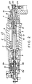
- a main spindle 1 is mounted on a base (not shown).
- the main spindle 1 is supported in such a manner that it can be rotated with its axis being the center and can be moved back and forth along the coordinate axis Z.
- the main spindle 1 is formed in a cylindrical shape, and a chuck 2 for gripping a work is attached to one end of the main spindle.
- the chuck 2 is constructed to grip a rod-shaped work 3.
- the work 3 is fed from the inside of main spindle 1 toward the chuck 2 by a specified amount, following the advance of main spindle 1 toward a cutting tool 4 (a cutter for main machining) along the coordinate axis Z.
- the cutting tool 4 is mounted in such a manner that it can move back and forth along the coordinate axis X.
- a back spindle 5 is mounted in parallel to the main spindle.
- the back spindle 5 is supported at both end portions by bearings 7, 7 (shown in Fig. 2) within a back head stock 6 and can be moved back and forth along the coordinate axes Z and X together with the back head stock 6.
- the back spindle 5 is formed in a cylindrical shape, and incorporates a collet chuck 8 for gripping a tool.
- the collet chuck 8 is located on the side of work 3 of the back spindle 5.
- the inner surface of the back spindle 5 is formed into a conical shape as a guide passage 9 for a conical holder 20 on a later descirbed back spindle tool 19.
- the collet chuck 8 is attached to one end of a rod 10.
- This rod 10 is supported by two guide bushes 11 and can be moved on the inside of the back spindle 5.
- the rod 10 is pushed toward the other end of the back spindle 5 (indicated by the arrow A in Fig. 2) by a belleville spring 12. In this pushed condition, the collet chuck 8 is closed and clamps the chucked portion 21 of the conical holder 20.
- a hydraulic actuator 13 is positioned at the other end of the rod 10.
- the hydraulic actuator 13 is constructed in such a manner that the tip of a piston 13c presses the other end of the rod 10 by supplying oil into a pressure oil chamber 13a while draining oil from a pressure oil chamber 13b.
- the rod 10 When the rod 10 is pressed, the rod moves against the force of the belleville spring 12. Then, the collet chuck 8 protrudes into the guide passage 9 and opens to unclamp the chucked portion 21 of the conical holder 20.
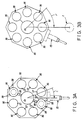
- a turret tool rest 14 is positioned in a position facing the cutting tool 4 via the work 3.
- the tool rest 14 is installed in such a manner that its axis of rotation O1 is in parallel to the axis of the main spindle 1 and it can be moved back and forth along the coordinate axes Z and X.
- the tool rest 14 On the peripheral surface of the tool rest 14, a cutting tool 15 is mounted.
- the tool rest 14 can be equipped with a total of eight cutting tools 15 radially from its axis of rotation O1 when being fully equipped.
- a drill among eight cutting tools is shown as an example, and other seven tools are not shown.
- a tool holder 16 On the surface side of the tool rest 14, eight tool holders 16 are disposed radially from the axis of rotation O1 (refer to Fig. 3A).
- a tool holder 16 is composed of a through hole 17 and three click stoppers 18 to hold a back spindle tool 19.
- the through hole 17 extends through the tool rest 14.
- a click stopper 18 is installed in such manner that a small-diameter ball 18a protrudes toward the hole 17.
- the back spindle tool 19 has a conical holder 20.
- the top of the holder 20 is integrally attached to a chucked portion 21.
- the bottom of the holder 20 is integrally attached to a collet chuck 22 for gripping a work.
- the collet chuck 22 for gripping a work.
- the collet chuck 22 is covered by a hollow screw 23 so that only its tip is exposed to the outside.
- the collet chuck 22 is so constructed that when a rod 24 abuts on the flat recessed portion 23a on the periphery surface of the hollow screw 23 and the back spindle 5 is turned in the forward or reverse direction, the hollow screw 23 moves longitudinally, resulting in clamping or unclamping condition.
- the rod 24 is mounted on a base (not shown).
- an annular groove 25 is formed, with which the small-diameter ball 18a of the chick stopper 18 engages.
- the back spindle tool 26 includes a drill 27 or other tools, which is attached to the same portion as that of the collet chuck 22.
- the back spindle 5, together with the back head stock 6, is advanced toward the tool rest 14 along the coordinate axis X (indicated by the arrow B in Fig. 1).
- the advance of the back spindle 5 stops.
- the tool rest 14 is rotated around the axis of rotation O1 (indicated by the arrow C in Fig. 3A).
- the rotation of the tool rest 14 stops.
- the back spindle 5, together with the back head stock 6, advances toward the tool holder 16 along the coordinate axis Z (indicated by the arrow D in Fig. 1).
- the groove 25 of the holder 20 engages with the small-diameter ball 18a of the click stopper 18, the advance of the back spindle 5 stops.
- the tool rest 14 is rotated around the axis of rotation O1 (indicated by the arrow F in Fig. 3A).
- the back spindle tool 26 having a tool to be used in the next process, for example a drill 27, faces the chuck 8 of the back spindle 5, the rotation of the tool rest 14 stops.
- the back spindle 5, together with the back head stock 6, advances agian along the coordinate axis Z (indicated by the arrow G in Fig. 1) until the empty chuck 8 abuts on the chucked portion 21 of the holder 20, where the advance of the back spindle 14 stops.
- the drill 27 is mounted on the back spindle 5 as a tool to be used in the next process.
- each tool holder 16 contains a back spindle tool having a different kind of chuck for gripping a work, such kind of chuck for gripping a work other than a drill or other tools can be mounted on the back spindle 5 when the above-described operation is performed repeatedly.
- a plurality of kinds of chucks for gripping a work and a drill or other tools can be mounted on the back spindle, so that the number of work processes which can be performed on the back spindle, for example the holder of a work with the chuck or the front machining of a work with a drill can be realized. Therefore, the embodiment enhances the utility of the back spindle and meets the requirement for the production of multi-product small-volume parts.
- the turret tool rest is equipped with tool holders for holding the back spindle tools, a mounting area dedicated to the tool holders is not needed on the machine, which makes the entire machine compact.
- a plurality of kinds of chucks for gripping a work and a drill or other tools can be mounted on the back spindle since the chuck for tool for clamping and unclamping the back spindle tool is mounted on the work side of the back spindle as described above. Therefore, the number of work processes which can be performed on the back spindle, for example, the holding of a work with the chuck or the front machining of a work with a drill can be realized.
- the turret tool rest is equipped with tool holders for holding the back spindle tool, so a mounting area dedicated to the tool holders is not needed on the machine, which makes the entire machine compact.
Landscapes
- Engineering & Computer Science (AREA)
- Mechanical Engineering (AREA)
- Turning (AREA)
Applications Claiming Priority (2)
| Application Number | Priority Date | Filing Date | Title |
|---|---|---|---|
| JP3114913A JPH04343601A (ja) | 1991-05-20 | 1991-05-20 | Cnc複合自動旋盤 |
| JP114913/91 | 1991-05-20 |
Publications (2)
| Publication Number | Publication Date |
|---|---|
| EP0514709A2 true EP0514709A2 (fr) | 1992-11-25 |
| EP0514709A3 EP0514709A3 (en) | 1993-01-13 |
Family
ID=14649768
Family Applications (1)
| Application Number | Title | Priority Date | Filing Date |
|---|---|---|---|
| EP19920107665 Withdrawn EP0514709A3 (en) | 1991-05-20 | 1992-05-06 | Computerized numerical control automatic complex lathe |
Country Status (5)
| Country | Link |
|---|---|
| US (1) | US5310397A (fr) |
| EP (1) | EP0514709A3 (fr) |
| JP (1) | JPH04343601A (fr) |
| KR (1) | KR100212680B1 (fr) |
| CN (1) | CN1068524A (fr) |
Families Citing this family (2)
| Publication number | Priority date | Publication date | Assignee | Title |
|---|---|---|---|---|
| JPH07276101A (ja) * | 1994-04-07 | 1995-10-24 | Star Micronics Co Ltd | 自動旋盤 |
| US5751586A (en) * | 1995-12-01 | 1998-05-12 | Grabovac; Bosko | CNC machine tool |
Family Cites Families (10)
| Publication number | Priority date | Publication date | Assignee | Title |
|---|---|---|---|---|
| US4404727A (en) * | 1981-02-24 | 1983-09-20 | Kearney & Trecker Corporation | Machine tool operable as both a chucking type lathe and as a machining center |
| DE3143409A1 (de) * | 1981-11-02 | 1983-05-11 | Heyligenstaedt & Co, Werkzeugmaschinenfabrik Gmbh, 6300 Giessen | Drehmaschine |
| US4663823A (en) * | 1982-03-10 | 1987-05-12 | Renishaw Plc | Machine tool |
| JPS61288963A (ja) * | 1985-06-12 | 1986-12-19 | Mitsubishi Metal Corp | 数値制御工作機械 |
| DE3530982A1 (de) * | 1985-08-30 | 1987-03-12 | Gildemeister Ag | Zweispindlige, numerisch gesteuerte drehmaschine |
| DE3626324A1 (de) * | 1986-08-02 | 1988-02-04 | Pittler Ag Maschf | Doppelspindel-drehmaschine |
| JP2663346B2 (ja) * | 1987-08-05 | 1997-10-15 | シチズン時計株式会社 | 旋 盤 |
| DE8713204U1 (de) * | 1987-10-01 | 1987-11-12 | Gildemeister Ag, 4800 Bielefeld | Werkzeugmaschine mit zwei Werkstückspindeln |
| JPH01183301A (ja) * | 1988-01-14 | 1989-07-21 | Hiroshi Kishi | 数値制御自動旋盤 |
| JPH01240201A (ja) * | 1988-03-19 | 1989-09-25 | Star Micronics Co Ltd | 自動旋盤における2次加工装置 |
-
1991
- 1991-05-20 JP JP3114913A patent/JPH04343601A/ja active Pending
-
1992
- 1992-05-06 EP EP19920107665 patent/EP0514709A3/en not_active Withdrawn
- 1992-05-08 US US07/880,722 patent/US5310397A/en not_active Expired - Fee Related
- 1992-05-18 KR KR1019920008360A patent/KR100212680B1/ko not_active Expired - Fee Related
- 1992-05-20 CN CN92104074A patent/CN1068524A/zh active Pending
Also Published As
| Publication number | Publication date |
|---|---|
| CN1068524A (zh) | 1993-02-03 |
| KR100212680B1 (ko) | 1999-08-02 |
| JPH04343601A (ja) | 1992-11-30 |
| KR920021244A (ko) | 1992-12-18 |
| EP0514709A3 (en) | 1993-01-13 |
| US5310397A (en) | 1994-05-10 |
Similar Documents
| Publication | Publication Date | Title |
|---|---|---|
| US5815902A (en) | Rotary transfer machine | |
| EP0375783B1 (fr) | Machine-outil | |
| US8591389B2 (en) | Tool transfer system | |
| EP0215209A2 (fr) | Machine-outil | |
| US3813745A (en) | Dual turret lathe | |
| US4308771A (en) | Tool holder for chucker lathe | |
| US5945009A (en) | Apparatus for processing workpieces by spark erosion | |
| DE3881867D1 (de) | Drehautomat zum verarbeiten von werkstoffstangen. | |
| JP2663346B2 (ja) | 旋 盤 | |
| US5310397A (en) | Computerized numerical control automatic complex lathe | |
| JP3621043B2 (ja) | Nc旋盤による傾斜穴加工方法、傾斜穴加工用nc旋盤及びnc旋盤に使用される傾斜穴加工用チャック | |
| JP2001018101A (ja) | 主軸移動型自動旋盤、そのための支持ユニットそして位置決め治具 | |
| JP7383278B2 (ja) | 加工機用ワークホルダー | |
| JPH03202244A (ja) | ワークのクランプ装置 | |
| JPH0637842Y2 (ja) | オートローディング装置 | |
| JPH0435042Y2 (fr) | ||
| JP2554247B2 (ja) | カツタ−ヘツド交換型工作機械 | |
| CN217596705U (zh) | 一种可定位加工的磨床 | |
| JP6990334B1 (ja) | 工具クランプ装置 | |
| GB2080174A (en) | Tool holder for row of tools | |
| JPH05293734A (ja) | 工具ホルダ | |
| JPS6464707A (en) | Automatic exchanger for collet unit | |
| JPS6374502A (ja) | 数値制御自動旋盤 | |
| SU1609550A1 (ru) | Двухшпиндельный токарный станок | |
| JPH0329049Y2 (fr) |
Legal Events
| Date | Code | Title | Description |
|---|---|---|---|
| PUAI | Public reference made under article 153(3) epc to a published international application that has entered the european phase |
Free format text: ORIGINAL CODE: 0009012 |
|
| PUAL | Search report despatched |
Free format text: ORIGINAL CODE: 0009013 |
|
| AK | Designated contracting states |
Kind code of ref document: A2 Designated state(s): CH DE LI |
|
| AK | Designated contracting states |
Kind code of ref document: A3 Designated state(s): CH DE LI |
|
| STAA | Information on the status of an ep patent application or granted ep patent |
Free format text: STATUS: THE APPLICATION IS DEEMED TO BE WITHDRAWN |
|
| 18D | Application deemed to be withdrawn |
Effective date: 19930714 |