EP0514800A2 - Dispositif pour flottation pneumatique - Google Patents
Dispositif pour flottation pneumatique Download PDFInfo
- Publication number
- EP0514800A2 EP0514800A2 EP92108321A EP92108321A EP0514800A2 EP 0514800 A2 EP0514800 A2 EP 0514800A2 EP 92108321 A EP92108321 A EP 92108321A EP 92108321 A EP92108321 A EP 92108321A EP 0514800 A2 EP0514800 A2 EP 0514800A2
- Authority
- EP
- European Patent Office
- Prior art keywords
- separation vessel
- outlet
- flotation
- carrying
- nozzle
- Prior art date
- Legal status (The legal status is an assumption and is not a legal conclusion. Google has not performed a legal analysis and makes no representation as to the accuracy of the status listed.)
- Granted
Links
- 238000005188 flotation Methods 0.000 title claims abstract description 36
- 238000000926 separation method Methods 0.000 claims abstract description 31
- 239000002002 slurry Substances 0.000 claims description 16
- 239000010802 sludge Substances 0.000 claims description 15
- 239000006260 foam Substances 0.000 claims description 10
- 238000006073 displacement reaction Methods 0.000 claims description 6
- 238000005273 aeration Methods 0.000 claims 1
- 239000013049 sediment Substances 0.000 abstract description 6
- 239000007787 solid Substances 0.000 description 14
- 239000002245 particle Substances 0.000 description 2
- 238000009825 accumulation Methods 0.000 description 1
- 230000015572 biosynthetic process Effects 0.000 description 1
- 230000000694 effects Effects 0.000 description 1
- 230000002349 favourable effect Effects 0.000 description 1
- 238000003958 fumigation Methods 0.000 description 1
- 239000000463 material Substances 0.000 description 1
- 230000000717 retained effect Effects 0.000 description 1
- 238000001228 spectrum Methods 0.000 description 1
Images
Classifications
-
- B—PERFORMING OPERATIONS; TRANSPORTING
- B03—SEPARATION OF SOLID MATERIALS USING LIQUIDS OR USING PNEUMATIC TABLES OR JIGS; MAGNETIC OR ELECTROSTATIC SEPARATION OF SOLID MATERIALS FROM SOLID MATERIALS OR FLUIDS; SEPARATION BY HIGH-VOLTAGE ELECTRIC FIELDS
- B03D—FLOTATION; DIFFERENTIAL SEDIMENTATION
- B03D1/00—Flotation
- B03D1/14—Flotation machines
- B03D1/24—Pneumatic
-
- B—PERFORMING OPERATIONS; TRANSPORTING
- B03—SEPARATION OF SOLID MATERIALS USING LIQUIDS OR USING PNEUMATIC TABLES OR JIGS; MAGNETIC OR ELECTROSTATIC SEPARATION OF SOLID MATERIALS FROM SOLID MATERIALS OR FLUIDS; SEPARATION BY HIGH-VOLTAGE ELECTRIC FIELDS
- B03D—FLOTATION; DIFFERENTIAL SEDIMENTATION
- B03D1/00—Flotation
- B03D1/02—Froth-flotation processes
- B03D1/028—Control and monitoring of flotation processes; computer models therefor
-
- B—PERFORMING OPERATIONS; TRANSPORTING
- B03—SEPARATION OF SOLID MATERIALS USING LIQUIDS OR USING PNEUMATIC TABLES OR JIGS; MAGNETIC OR ELECTROSTATIC SEPARATION OF SOLID MATERIALS FROM SOLID MATERIALS OR FLUIDS; SEPARATION BY HIGH-VOLTAGE ELECTRIC FIELDS
- B03D—FLOTATION; DIFFERENTIAL SEDIMENTATION
- B03D1/00—Flotation
- B03D1/14—Flotation machines
- B03D1/1412—Flotation machines with baffles, e.g. at the wall for redirecting settling solids
-
- B—PERFORMING OPERATIONS; TRANSPORTING
- B03—SEPARATION OF SOLID MATERIALS USING LIQUIDS OR USING PNEUMATIC TABLES OR JIGS; MAGNETIC OR ELECTROSTATIC SEPARATION OF SOLID MATERIALS FROM SOLID MATERIALS OR FLUIDS; SEPARATION BY HIGH-VOLTAGE ELECTRIC FIELDS
- B03D—FLOTATION; DIFFERENTIAL SEDIMENTATION
- B03D1/00—Flotation
- B03D1/14—Flotation machines
- B03D1/1431—Dissolved air flotation machines
-
- B—PERFORMING OPERATIONS; TRANSPORTING
- B03—SEPARATION OF SOLID MATERIALS USING LIQUIDS OR USING PNEUMATIC TABLES OR JIGS; MAGNETIC OR ELECTROSTATIC SEPARATION OF SOLID MATERIALS FROM SOLID MATERIALS OR FLUIDS; SEPARATION BY HIGH-VOLTAGE ELECTRIC FIELDS
- B03D—FLOTATION; DIFFERENTIAL SEDIMENTATION
- B03D1/00—Flotation
- B03D1/14—Flotation machines
- B03D1/1443—Feed or discharge mechanisms for flotation tanks
- B03D1/1456—Feed mechanisms for the slurry
-
- B—PERFORMING OPERATIONS; TRANSPORTING
- B03—SEPARATION OF SOLID MATERIALS USING LIQUIDS OR USING PNEUMATIC TABLES OR JIGS; MAGNETIC OR ELECTROSTATIC SEPARATION OF SOLID MATERIALS FROM SOLID MATERIALS OR FLUIDS; SEPARATION BY HIGH-VOLTAGE ELECTRIC FIELDS
- B03D—FLOTATION; DIFFERENTIAL SEDIMENTATION
- B03D1/00—Flotation
- B03D1/14—Flotation machines
- B03D1/1443—Feed or discharge mechanisms for flotation tanks
- B03D1/1462—Discharge mechanisms for the froth
Definitions
- the invention is directed to a device for carrying out a pneumatic flotation, formed from a separating vessel with an outlet for the flotation outlets and with a foam-absorbing overflow channel with an associated outlet and with a fumigation device arranged outside the separating vessel and connected via a pipeline to the separating vessel floating turbidity.
- the gassing device In the case of pneumatic flotation, the gassing device generates gas bubbles which, under certain conditions, accumulate on the solids to be discharged. This creates gas bubble-solid complexes in the slurry, which are discharged as foam in the separation vessel.
- the gassing device attempts to exert a large influence on the attachment of the gas bubbles to the solids to be discharged and thus on the formation of floatable foam-forming gas bubble-solid complexes.
- German patent DE 31 11 506 describes a device for carrying out pneumatic flotation, in which the slurry to be flotated is supplied to the several gassing devices arranged in a ring around the separation vessel, and the slurry loaded with gas bubbles is then fed from below through several inlets, which are largely arranged in the deepest area of the separating vessel, which is conical at the bottom, are guided into the separating vessel.
- the object of the present invention is to provide a device for carrying out a pneumatic flotation which, while avoiding the existing disadvantages, enables an improvement in the attachment of the gas bubbles to the solids to be discharged, while at the same time eliminating the large number of gassing devices and slurry inlets into the separation vessel represents a structurally simple and inexpensive version.
- the fumigated sludge is first led from the gassing device via a pipe to the lower region of the separation vessel to a sludge outlet device with a pressure build-up nozzle, which causes a cross-sectional constriction and thus builds up pressure in the pipe.
- a sludge outlet device with a pressure build-up nozzle, which causes a cross-sectional constriction and thus builds up pressure in the pipe.
- smaller gas bubbles are generated in a defined manner.
- the specific gas bubble surface area is increased and thus the accumulation of the gas bubbles on the solids to be discharged is increased. Due to the longer contact time given by the length of the pipeline, the gas bubbles are increasingly given the possibility of attachment to the solid and thus additionally have a favorable influence on the flotation result.
- the outflow of the sludge takes place first in a pressure reduction chamber, whereby a pressure reduction takes place and only then from there in the opposite Direction via several turbidity outlet nozzles into the separation vessel.
- the size of the pressure relief chamber and the number and size of the slurry outlet nozzles are selected so that the slurry in the pressure relief chamber is initially calmed down and then the slurry flows slowly and laminarly upwards into the separating vessel, the gas bubble size increasing as a result of the pressure reduction.
- a control of the gas bubble size is adapted to the solid to be discharged without influencing the rate of entry of the sludge into the separation vessel.
- the central arrangement of the gassing device means that only one gassing device is required.
- the design of the separating vessel is additionally simplified by the further design of the separating vessel, to arrange the discharge of the flotation outlets centrally at the bottom of the separating vessel.
- the turbidity outlet device can advantageously be raised according to the invention in order to largely avoid a collision of the upwardly flowing gassed sludge with the downwardly sedimenting flotation outlets, and furthermore the conical displacement body can Foam area should be limited in a ring shape so that a certain desired foam flow rate (in the direction of the overflow channel) is not undershot.
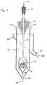
- the flotation device consists of a separating vessel (10) which tapers conically downwards, with a foam overflow at the upper end of the cylindrical part of the separating vessel and with a foam-absorbing overflow channel (20) and associated lateral foam discharge (11) and a central outlet ( 12) for the entire flotation outlets (28) at the lower end of the conical part of the separation vessel.
- a cone-shaped, vertically displaceable displacement body (17) At the upper end of the separation vessel (10) there is a cone-shaped, vertically displaceable displacement body (17).
- Inside the separation vessel (10) is in the lower one Area a short cylindrical downwardly tapering inner tube (14) with an outlet opening (18) for the flotation outlets at the lower end of the conical part.
- the vertically displaceable slurry outlet device (13) is located in this inner tube and is connected to the gassing device (15) arranged centrally above the separation vessel (10) by a pipeline (16).
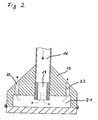
- the pipeline (16) in the turbidity outlet device (13) opens into a pressure build-up nozzle (19), which has a pressure reduction chamber (21) and this in turn via a turbidity outlet nozzle (22) with the separation vessel (10). communicates.
- the slurry (23) to be floated is fumigated in the gassing device (15) and reaches the pressure build-up nozzle (19) via the pipeline (16), which creates a defined pressure build-up within the pipeline (16) due to its cross-sectional constriction.
- the pressurized fumigated slurry reaches the pressure reduction chamber (21) at high flow velocity, where, due to the available chamber volume in connection with the slurry outlet nozzles (22), the effective cross section of which is at least twice as large as the cross section of the pressure build-up nozzles (19 ), the pressure is reduced to such an extent that the sludge can emerge from the sludge outlet nozzles (22) at low speed and without turbulence into the separation vessel (10).
- Large flotation outlet particles (26) which sediment down immediately after leaving the turbid outlet nozzles, are guided through the conically tapering part of the inner tube (14) to the outlet opening (18) and arrive thence to the common outlet for the flotation outlets (12).
Landscapes
- Engineering & Computer Science (AREA)
- Life Sciences & Earth Sciences (AREA)
- Biotechnology (AREA)
- General Engineering & Computer Science (AREA)
- Physical Water Treatments (AREA)
- Paper (AREA)
- Fish Paste Products (AREA)
- Separation Of Solids By Using Liquids Or Pneumatic Power (AREA)
- Electrical Discharge Machining, Electrochemical Machining, And Combined Machining (AREA)
- Jet Pumps And Other Pumps (AREA)
- Treatment Of Sludge (AREA)
Applications Claiming Priority (2)
| Application Number | Priority Date | Filing Date | Title |
|---|---|---|---|
| DE4116645 | 1991-05-22 | ||
| DE4116645A DE4116645A1 (de) | 1991-05-22 | 1991-05-22 | Vorrichtung zur durchfuehrung einer pneumatischen flotation |
Publications (3)
| Publication Number | Publication Date |
|---|---|
| EP0514800A2 true EP0514800A2 (fr) | 1992-11-25 |
| EP0514800A3 EP0514800A3 (en) | 1995-02-22 |
| EP0514800B1 EP0514800B1 (fr) | 1996-07-31 |
Family
ID=6432144
Family Applications (1)
| Application Number | Title | Priority Date | Filing Date |
|---|---|---|---|
| EP92108321A Expired - Lifetime EP0514800B1 (fr) | 1991-05-22 | 1992-05-16 | Dispositif pour flottation pneumatique |
Country Status (7)
| Country | Link |
|---|---|
| EP (1) | EP0514800B1 (fr) |
| AT (1) | ATE140882T1 (fr) |
| CS (1) | CS154592A3 (fr) |
| DE (2) | DE4116645A1 (fr) |
| ES (1) | ES2090409T3 (fr) |
| HU (1) | HU211098B (fr) |
| PL (1) | PL167874B1 (fr) |
Cited By (5)
| Publication number | Priority date | Publication date | Assignee | Title |
|---|---|---|---|---|
| RU2393023C2 (ru) * | 2008-05-29 | 2010-06-27 | Федеральное государственное образовательное учреждение высшего профессионального образования "Государственный технологический университет "Московский институт стали и сплавов" | Пневматическая флотационная машина |
| RU2491132C1 (ru) * | 2012-03-01 | 2013-08-27 | Федеральное государственное автономное образовательное учреждение высшего профессионального образования "Национальный исследовательский технологический университет "МИСиС" | Пневматическая флотационная машина |
| RU2614170C1 (ru) * | 2016-05-23 | 2017-03-23 | Федеральное государственное автономное образовательное учреждение высшего образования "Национальный исследовательский технологический университет "МИСиС" | Пневматическая флотационная машина |
| CN115739405A (zh) * | 2022-11-09 | 2023-03-07 | 淮北矿业股份有限公司涡北选煤厂 | 一种利用劣质煤洗选炼焦精煤的方法和装置 |
| CN117861870A (zh) * | 2024-03-12 | 2024-04-12 | 北矿科技股份有限公司 | 浮选设备以及浮选系统 |
Families Citing this family (2)
| Publication number | Priority date | Publication date | Assignee | Title |
|---|---|---|---|---|
| RU2132749C1 (ru) * | 1998-05-12 | 1999-07-10 | Открытое акционерное общество "Уралмеханобр" | Флотационная пневматическая колонная машина |
| RU2191074C1 (ru) * | 2001-11-06 | 2002-10-20 | Видуецкий Марк Григорьевич | Флотационная пневматическая колонная машина |
Family Cites Families (10)
| Publication number | Priority date | Publication date | Assignee | Title |
|---|---|---|---|---|
| US2130920A (en) * | 1936-07-06 | 1938-09-20 | Mays Mfg Company Inc | Memorandum-pad holder for telephones |
| FR2206985B1 (fr) * | 1972-11-22 | 1977-04-22 | Saint Gobain Techn Nouvelles | |
| US4338192A (en) * | 1978-12-18 | 1982-07-06 | Ingersoll-Rand Company | Clarifier bubble generation and distribution nozzle |
| US4255262A (en) * | 1979-03-26 | 1981-03-10 | U.S. Filter Corporation | Hydraulic powered mixing apparatus |
| DE3101221C2 (de) * | 1981-01-16 | 1983-09-22 | J.M. Voith Gmbh, 7920 Heidenheim | "Einrichtung zur Schaumflotation" |
| DE3144386C2 (de) * | 1981-11-07 | 1983-12-29 | J.M. Voith Gmbh, 7920 Heidenheim | Injektorflotationsapparat |
| FR2550469B1 (fr) * | 1983-08-09 | 1985-10-04 | Alsthom Atlantique | Injecteur de microbulles |
| EP0146235A3 (fr) * | 1983-10-21 | 1987-02-04 | The University Of Newcastle Research Associates Limited | Procédé de flottation |
| NL8602243A (nl) * | 1986-09-05 | 1988-04-05 | Facet Ind B V | Inrichting voor het door flotatie zuiveren van vloeistof en daarin toe te passen vloeistof-injekteur. |
| DE3733583C2 (de) * | 1987-10-03 | 1996-04-18 | Fan Engineering Gmbh | Vorrichtung zur Erzeugung von Mikroblasen aus begasten Flüssigkeiten für die Flotation von Schlämmen |
-
1991
- 1991-05-22 DE DE4116645A patent/DE4116645A1/de not_active Withdrawn
-
1992
- 1992-05-16 AT AT92108321T patent/ATE140882T1/de active
- 1992-05-16 DE DE59206835T patent/DE59206835D1/de not_active Expired - Lifetime
- 1992-05-16 ES ES92108321T patent/ES2090409T3/es not_active Expired - Lifetime
- 1992-05-16 EP EP92108321A patent/EP0514800B1/fr not_active Expired - Lifetime
- 1992-05-21 HU HU9201693A patent/HU211098B/hu not_active IP Right Cessation
- 1992-05-22 PL PL92294649A patent/PL167874B1/pl not_active IP Right Cessation
- 1992-05-22 CS CS921545A patent/CS154592A3/cs unknown
Cited By (6)
| Publication number | Priority date | Publication date | Assignee | Title |
|---|---|---|---|---|
| RU2393023C2 (ru) * | 2008-05-29 | 2010-06-27 | Федеральное государственное образовательное учреждение высшего профессионального образования "Государственный технологический университет "Московский институт стали и сплавов" | Пневматическая флотационная машина |
| RU2491132C1 (ru) * | 2012-03-01 | 2013-08-27 | Федеральное государственное автономное образовательное учреждение высшего профессионального образования "Национальный исследовательский технологический университет "МИСиС" | Пневматическая флотационная машина |
| RU2614170C1 (ru) * | 2016-05-23 | 2017-03-23 | Федеральное государственное автономное образовательное учреждение высшего образования "Национальный исследовательский технологический университет "МИСиС" | Пневматическая флотационная машина |
| CN115739405A (zh) * | 2022-11-09 | 2023-03-07 | 淮北矿业股份有限公司涡北选煤厂 | 一种利用劣质煤洗选炼焦精煤的方法和装置 |
| CN115739405B (zh) * | 2022-11-09 | 2025-07-18 | 淮北矿业股份有限公司涡北选煤厂 | 一种利用劣质煤洗选炼焦精煤的方法和装置 |
| CN117861870A (zh) * | 2024-03-12 | 2024-04-12 | 北矿科技股份有限公司 | 浮选设备以及浮选系统 |
Also Published As
| Publication number | Publication date |
|---|---|
| EP0514800A3 (en) | 1995-02-22 |
| ATE140882T1 (de) | 1996-08-15 |
| HU211098B (en) | 1995-10-30 |
| HU9201693D0 (en) | 1992-08-28 |
| ES2090409T3 (es) | 1996-10-16 |
| CS154592A3 (en) | 1992-12-16 |
| EP0514800B1 (fr) | 1996-07-31 |
| PL294649A1 (en) | 1993-01-25 |
| HUT62827A (en) | 1993-06-28 |
| PL167874B1 (en) | 1995-11-30 |
| DE59206835D1 (de) | 1996-09-05 |
| DE4116645A1 (de) | 1992-11-26 |
Similar Documents
| Publication | Publication Date | Title |
|---|---|---|
| DE3789795T2 (de) | Säulenflotationsverfahren und -vorrichtung. | |
| DE3144386A1 (de) | Injektorapparat mit einer verengungsstelle eines dieser nachgeschalteten mischrohrs | |
| DE3111506C2 (de) | Begasungseinrichtung für Flotationsanlagen | |
| DE2246676B2 (de) | Reaktionskristallisator | |
| DE1067743B (de) | Vorrichtung zum Aufbereiten von Mineralien und anderen Stoffen nach dem Flotationsverfahren | |
| DE4432042A1 (de) | Begasungs-/Flotations-Reaktor und Regeleinrichtung | |
| DE2420482A1 (de) | Verfahren und anlage zur flotation | |
| EP0338198A1 (fr) | Réservoir de séparation pour des suspensions de boues activées et d'eaux usées | |
| EP0514800B1 (fr) | Dispositif pour flottation pneumatique | |
| DE2812105A1 (de) | Verfahren und vorrichtung zum trennen von stoffen durch flotation | |
| DE2359655C3 (de) | Vorrichtung zum Klaren von feste Stoffe enthaltenden Flüssigkeiten | |
| DE3801905C2 (fr) | ||
| DE2359656C3 (de) | Vorrichtung zum Klären von feste Stoffe enthaltendem Abwasser o.dgl. Flüssigkeiten | |
| DE4414272A1 (de) | Vorrichtung zur Begasung einer Suspension | |
| DE1182161B (de) | Zentrifugalflotationszelle | |
| DE2727398A1 (de) | Flotationsapparat | |
| DE3417327A1 (de) | Verfahren und vorrichtung zur aufrechterhaltung eines vorbestimmten truebeniveaus in einer flotationszelle | |
| EP2424820A1 (fr) | Dispositif pour épurer des eaux usées, de préférence sur des bateaux | |
| DE2415940C3 (de) | Kanal für einen Behälter zur Begasung einer Flüssigkeit | |
| DE1158461B (de) | Zyklon zur flotativen Aufbereitung von feinkoernigen Mineraliengemengen | |
| DE2920869C2 (fr) | ||
| DE3918025C2 (fr) | ||
| DE69621795T2 (de) | Mischen | |
| DE3318739C1 (de) | Aufstromklassierer | |
| AT235227B (de) | Zentrifugalabscheider zur Feststoffsortierung in Schwertrüben |
Legal Events
| Date | Code | Title | Description |
|---|---|---|---|
| PUAI | Public reference made under article 153(3) epc to a published international application that has entered the european phase |
Free format text: ORIGINAL CODE: 0009012 |
|
| AK | Designated contracting states |
Kind code of ref document: A2 Designated state(s): AT BE DE ES GB IT NL |
|
| RAP1 | Party data changed (applicant data changed or rights of an application transferred) |
Owner name: ERZ- UND KOHLEFLOTATION GMBH |
|
| PUAL | Search report despatched |
Free format text: ORIGINAL CODE: 0009013 |
|
| AK | Designated contracting states |
Kind code of ref document: A3 Designated state(s): AT BE DE ES GB IT NL |
|
| 17P | Request for examination filed |
Effective date: 19950126 |
|
| 17Q | First examination report despatched |
Effective date: 19950727 |
|
| GRAH | Despatch of communication of intention to grant a patent |
Free format text: ORIGINAL CODE: EPIDOS IGRA |
|
| RAP1 | Party data changed (applicant data changed or rights of an application transferred) |
Owner name: KLOECKNER-HUMBOLDT-DEUTZ AKTIENGESELLSCHAFT |
|
| GRAH | Despatch of communication of intention to grant a patent |
Free format text: ORIGINAL CODE: EPIDOS IGRA |
|
| RAP1 | Party data changed (applicant data changed or rights of an application transferred) |
Owner name: IMHOF, RAINER, DR. Owner name: KLOECKNER-HUMBOLDT-DEUTZ AKTIENGESELLSCHAFT |
|
| GRAA | (expected) grant |
Free format text: ORIGINAL CODE: 0009210 |
|
| AK | Designated contracting states |
Kind code of ref document: B1 Designated state(s): AT BE DE ES GB IT NL |
|
| PG25 | Lapsed in a contracting state [announced via postgrant information from national office to epo] |
Ref country code: NL Free format text: LAPSE BECAUSE OF FAILURE TO SUBMIT A TRANSLATION OF THE DESCRIPTION OR TO PAY THE FEE WITHIN THE PRESCRIBED TIME-LIMIT Effective date: 19960731 |
|
| REF | Corresponds to: |
Ref document number: 140882 Country of ref document: AT Date of ref document: 19960815 Kind code of ref document: T |
|
| GBT | Gb: translation of ep patent filed (gb section 77(6)(a)/1977) |
Effective date: 19960809 |
|
| REF | Corresponds to: |
Ref document number: 59206835 Country of ref document: DE Date of ref document: 19960905 |
|
| ITF | It: translation for a ep patent filed | ||
| REG | Reference to a national code |
Ref country code: ES Ref legal event code: FG2A Ref document number: 2090409 Country of ref document: ES Kind code of ref document: T3 |
|
| REG | Reference to a national code |
Ref country code: ES Ref legal event code: FG2A Ref document number: 2090409 Country of ref document: ES Kind code of ref document: T3 |
|
| NLV1 | Nl: lapsed or annulled due to failure to fulfill the requirements of art. 29p and 29m of the patents act | ||
| RAP2 | Party data changed (patent owner data changed or rights of a patent transferred) |
Owner name: IMHOF, RAINER, DR. Owner name: DEUTZ AKTIENGESELLSCHAFT |
|
| PG25 | Lapsed in a contracting state [announced via postgrant information from national office to epo] |
Ref country code: AT Free format text: LAPSE BECAUSE OF NON-PAYMENT OF DUE FEES Effective date: 19970516 |
|
| PG25 | Lapsed in a contracting state [announced via postgrant information from national office to epo] |
Ref country code: BE Effective date: 19970531 |
|
| PLBE | No opposition filed within time limit |
Free format text: ORIGINAL CODE: 0009261 |
|
| STAA | Information on the status of an ep patent application or granted ep patent |
Free format text: STATUS: NO OPPOSITION FILED WITHIN TIME LIMIT |
|
| REG | Reference to a national code |
Ref country code: ES Ref legal event code: PC2A |
|
| 26N | No opposition filed | ||
| BERE | Be: lapsed |
Owner name: IMHOF RAINER Effective date: 19970531 Owner name: KLOCKNER-HUMBOLDT-DEUTZ A.G. Effective date: 19970531 |
|
| REG | Reference to a national code |
Ref country code: GB Ref legal event code: 732E |
|
| REG | Reference to a national code |
Ref country code: GB Ref legal event code: IF02 |
|
| PGFP | Annual fee paid to national office [announced via postgrant information from national office to epo] |
Ref country code: ES Payment date: 20100525 Year of fee payment: 19 |
|
| PGFP | Annual fee paid to national office [announced via postgrant information from national office to epo] |
Ref country code: DE Payment date: 20100413 Year of fee payment: 19 Ref country code: IT Payment date: 20100524 Year of fee payment: 19 |
|
| PGFP | Annual fee paid to national office [announced via postgrant information from national office to epo] |
Ref country code: GB Payment date: 20110526 Year of fee payment: 20 |
|
| PG25 | Lapsed in a contracting state [announced via postgrant information from national office to epo] |
Ref country code: IT Free format text: LAPSE BECAUSE OF NON-PAYMENT OF DUE FEES Effective date: 20110516 |
|
| REG | Reference to a national code |
Ref country code: DE Ref legal event code: R119 Ref document number: 59206835 Country of ref document: DE Effective date: 20111201 |
|
| REG | Reference to a national code |
Ref country code: GB Ref legal event code: PE20 Expiry date: 20120515 |
|
| PG25 | Lapsed in a contracting state [announced via postgrant information from national office to epo] |
Ref country code: GB Free format text: LAPSE BECAUSE OF EXPIRATION OF PROTECTION Effective date: 20120515 |
|
| REG | Reference to a national code |
Ref country code: ES Ref legal event code: FD2A Effective date: 20130417 |
|
| PG25 | Lapsed in a contracting state [announced via postgrant information from national office to epo] |
Ref country code: ES Free format text: LAPSE BECAUSE OF NON-PAYMENT OF DUE FEES Effective date: 20110517 |
|
| PG25 | Lapsed in a contracting state [announced via postgrant information from national office to epo] |
Ref country code: DE Free format text: LAPSE BECAUSE OF NON-PAYMENT OF DUE FEES Effective date: 20111201 |