EP0515470B1 - Zusätzliche aufbausysteme für lastfahrzeuge - Google Patents
Zusätzliche aufbausysteme für lastfahrzeuge Download PDFInfo
- Publication number
- EP0515470B1 EP0515470B1 EP91904124A EP91904124A EP0515470B1 EP 0515470 B1 EP0515470 B1 EP 0515470B1 EP 91904124 A EP91904124 A EP 91904124A EP 91904124 A EP91904124 A EP 91904124A EP 0515470 B1 EP0515470 B1 EP 0515470B1
- Authority
- EP
- European Patent Office
- Prior art keywords
- superstructure
- truck
- intermediate frame
- tubes
- locking
- Prior art date
- Legal status (The legal status is an assumption and is not a legal conclusion. Google has not performed a legal analysis and makes no representation as to the accuracy of the status listed.)
- Expired - Lifetime
Links
- 230000000295 complement effect Effects 0.000 title claims abstract description 12
- 230000008878 coupling Effects 0.000 description 4
- 238000010168 coupling process Methods 0.000 description 4
- 238000005859 coupling reaction Methods 0.000 description 4
- 239000010720 hydraulic oil Substances 0.000 description 3
- 238000004519 manufacturing process Methods 0.000 description 2
- 230000003213 activating effect Effects 0.000 description 1
- 239000000969 carrier Substances 0.000 description 1
- 238000000151 deposition Methods 0.000 description 1
- 230000005611 electricity Effects 0.000 description 1
- 238000005259 measurement Methods 0.000 description 1
- 239000003921 oil Substances 0.000 description 1
- 230000000284 resting effect Effects 0.000 description 1
Images


Classifications
-
- B—PERFORMING OPERATIONS; TRANSPORTING
- B60—VEHICLES IN GENERAL
- B60P—VEHICLES ADAPTED FOR LOAD TRANSPORTATION OR TO TRANSPORT, TO CARRY, OR TO COMPRISE SPECIAL LOADS OR OBJECTS
- B60P1/00—Vehicles predominantly for transporting loads and modified to facilitate loading, consolidating the load, or unloading
- B60P1/64—Vehicles predominantly for transporting loads and modified to facilitate loading, consolidating the load, or unloading the load supporting or containing element being readily removable
Definitions
- the present invention generally relates to complementary or building-up system or completing structure for trucks, in the following referred to as a "superstructure", and the invention is more particularly directed to a complementary system for trucks for making it possible to quickly and simply mounting of different types of superstructures or building-ups on a truck and for removing said superstructure therefrom respectively, or to quickly and simply replace a superstructure of one and the same truck, and comprising several lock guides fixedly mounted in predetermined positions in relation to the truck chassis and arranged to receive consoles or similar means on the superstructure for co-operation therewith, and means for lockingly connecting said consoles of the superstructure to said guides of the truck.
- the superstructure generally used to be fixed mounted on the truck chassis in the sense that the turntable, the load changer frame, the tank or reservoir, the concrete mixer etc. was bolted and welded to form a stationary or integral part of the truck chassis.
- the chassis of the truck is formed with several coupling means or quick- locks provided on exactly predetermined places of the chassis and on very accurately determined distances from each other and from the upper surface of the chassis frame.
- the superstructure or complementary structure is formed with an assisting support frame having matching connection means, for instance lock consoles, for lockingly engage the quick-locks of the truck chassis.
- the superstructures may be of different types, for instance a turntable for a semi-trailer, a load changing system, a so colled lift-dumper system, a tank or reservoir, a concrete mixer etc.
- the truck is moved backwards into position under such other superstructure which is standing on similar support legs on another place, and the superstructure is mounted oppositely to what is described above, that is by expelling the discharge cylinders of the chassis to engage the guiding consoles of the support frame of the super- structure and to raise the superstructure with the support legs, removing the support legs, lowering the discharge cylinders, whereby the lock consoles of the superstructure engages the stationary quick- locks of the chassis, and engaging the quick-locks so that the superstructure becomes safely secured on the truck chassis.
- a truck is delivered from the manufacturer without any built-up structure or superstructure at all, and for supplying the truck with such a superstructure the truck has to be moved to a superstructure manufacturer who mounts the quick-locks, the electical and hydraulical couplings, the oil tank for the hydraulic system etc.
- a system is known from SE-B-398.470 in which a lifting frame is mounted on the truck chassis, which lifting frame is capable of picking up a releasable truck platform which is standing on feet on the ground and to connect said platform to the the truck chassis, and vice versa.
- a problem with said known system is that the mounting of the superstructure system is relatively time consuming, and during the entire time of mounting said system the truck has to be standing inactive, and this leeds to rather great loss-of-use costs.
- the mounting of the quick-locks also needs great accuracy so that the quick-locks become located on exactly predetermined places corresponding to the location of the locking consoles of tie superstructure.
- special mounting jigs are used, and the superstructure manufacturer must have several types of jigs in stock suited for different types and different sizes of trucks. It is often also necessary to specially design the electrical and hydraulical conduits and tubes, the location of the hydraulic oil tank and other parts of the system so that said parts do not collide with parts already existing in the truck.
- the quick-locks become mounted on the chassis frame on exactly predetermined places from the truck drivers's cab and from the rear end of the truck respectively, on exactly predetermined distances from each other, and on exactly predetermined distances from the upper surface of the chassis frame so that the superstructure, upon locking of the quick-locks, becomes clamped to the upper surface of the chassis frame so as to avoid any possibility of play between the superstructure and the truck chassis.
- the object of the invention therefore to solve the problem of providing a complementary system or superstructure system for trucks, which system is pre-manufactured with a great accuracy, which has pre-mounted electrical and hydraulic conduits, pipes and couplings, hydraulic tanks, guide cylinders for the superstructure etc., and which system is of standard type and can be mounted on nearly any type of truck chassis, and which - above all - can be mounted on the truck chassis much quicker than has so far been possible, whereby it is possible to reduce the inactive time of the truck while being supplied with the superstructure as far as to 10-15%, or even still less, of the previously needed inactive, deadlock time.
- the complementary system or superstructure system is formed as a pre-manufactured intermediate frame of relatively small height and comprising both quick-locks and discharge means, all necessary hydraulic and electric means etc., whereby all parts of the intermediate frame apparatus are mounted in exactly predetermined positions, and which intermediate frame can be mounted on an available truck chassis by being connected thereto for instance with the assistance of the quick-locks.
- hydraulic actuation cylinders are double acting, floating hydraulic cylinders which at the same time actuate the quick-locking pins on both sides of the truck and both in locking and in releasing directions.
- figure 1 shows a known complementary system or superstructure system
- the figure discloses a complementary wagon bridge which has been lifted from the truck chassis and has been supplied with support legs, but before the truck has been moved off
- figure 2 shows a similar superstructure standing on the ground and with the truck moved off said structure.
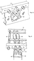
- Figure 3 is a fragmentary view from above and from behind of an intermediate frame for a superstructure according to the invention before said structure has been mounted on a truck chassis.
- Figure 4 shows a detail at the rear part of the apparatus of figure 3 in its mounted state
- figure 5 similarly shows a detail of an intermediate frame of the apparatus while mounting of said frame on a truck chassis.
- Figure 6 finally shows a preferred embodiment of an actuation means for the quick-locks in the apparatus according to the invention.
- Figure 1 shows a truck 1 having a known type of superstructure system with an exchangable wagon bridge 2 or a similar structure.
- the superstructure system comprises several quick-locks, in the illustrated case four quick-locks 3, the rearmost quick-lock of which is a twin quick-lock.
- the quick-locks are mounted on the outer sides of the truck frame 4 in accurately predetermined positions in the longitudinal direction of the truck and with accurately predetermined distances from each other and from the upper surface of the frame.
- consoles 5 On the exchangable wagon bridge there are consoles 5 which, as known, are formed with a cross bar 6 adapted to slidingly engage a V-shaped groove of the quick-lock 3 and to become locked therein by means of a pin 7 having a conical outer end, and which is adapted to be screwed into said V-shaped groove thereby pressing the consoles 5 downwards with a slight play to the bottom of the V-groove to lock the wagon bridge 2 to the chassis frame 4 of the truck.
- several lift cylinders 8 are mounted on the chassis frame 4.
- Said lift cylinders 8 are arranged to engage guide yokes 9 of the wagon bridge 2 when being expelled, so that the wagon bridge 2 can be lifted some distance 10 from the chassis frame 4.
- support legs 11 can be mounted in carriers 12 of the wagon bridge, which support legs 11, when standing on the ground, keep the wagon bridge in the lifted position so that the truck can be moved off to collect another superstructure.
- the wagon bridge 2 which has been lifted off the truck can be left standing on its support legs 11 until said wagon bridge is to be used the next time.
- the apparatus comprises a separate, intermediate frame 13 including all necessary means for locking the superstructure and for handling of the superstructures of the truck.
- the finally completed intermediate frame 13 is arranged to be fixed mounted on the truck chassis 4 and to thereafter receive different superstructures or building-ups which are being connected to eyelets of the intermediate or assisting frame 13.
- the intermediate frame 13 can made low, for instance with a height of only 4-8 cm, and this insignificant increase of height is quite acceptable.
- the intermediate frame is made of two longitudinally extending square tubes 14 and 15 which are interconnected and are kept on a predetermined distance from each other by several cross cylindrical tubes 16.
- the transversal distance between the square tubes 14 and 15 is calculated considering the width between the outer edges of the actual truck.
- Both the hollow square tubes 14 and 15 and the cylindrical tubes 16 can be used for placing of the electrical conduits, the hydraulic hoses etc., so that said conduits and hoses are well protected.
- the cylindrical tubes 16, which preferably extend right through the longitudinal square tubes 14 and 15 and project a slight distance out from the sides thereof also can be used for connection of different parts of the apparatus.
- quick-locks for instance the quick-locks 17 and 18 of figure 3, are welded on exactly predetermined distances from each other.
- the complete manufacture of the intermediate frame 13 with the quick-locks and all other details is made in quantities in a factory using a standard jig for any and all types and sizes of trucks and superstructures.
- the quick-locks 17 and 18 comprises a clamp 19 forming a substantially V-shaped groove 20 having a rounded bottom.
- a cross bar of a console (see 6 of figure 1) in a superstructure is adapted to be guided into and to be received in said V-groove 20 and to be locked by means of a locking rod 21 having a conical end 22 which presses the cross bar of the super structure downwards in the locking groove 20.
- the quick-lock is formed with a bottom plate 23 by means of which the quick-locks, and thereby the entire intermediate frame, can be mounted on the chassis frame 4 of the vehicle.
- the mounting can be made in that a console 24 is simply welded to the side surface of the chassis frame, whereupon the bottom plate 23 of the quick-lock is welded to the upper surface of the console 24.
- the quick-locks preferably are formed so as to project a slight distance down from the frame tubes 14, 15.
- the rear end of the intermediate frame 13 is formed with two quick-locks 18 (a twin quick-lock), which are (is) mounted on a common support console 25, which, in connection to the mounting of the intermediate frame on the truck chassis, is bolt connected directly to the chassis frame, whereupon the quick-lock or quick-locks are welded to said support console 25.
- a twin quick-lock a twin quick-lock
- a lift cylinder 26 on each side of the intermediate frame.
- Said lift cylinders 26 are arranged to co-operate with a guide yoke (see 9 of figure 1) of the superstructure as explained in connection to figure 1.
- the lift cylinders 26 are used both for lifting the superstructure when removing the intermediate frame and depositing said frame on support legs, and for lowering and guiding a new superstructure into a locking position with the locking console of the superstructure located in the quick-locks 17 and 18.
- the lift cylinders are enclosed in a carrier 27 which is connected both to the support console 25 and to a cross tube end 28 which is also a transversal interconnecting element of the intermediate frame 13.
- a quick-lock on the left side and a quick-lock on the right side of the intermediate frame 13 provides a pair of locks co-operating with locking rods 21.
- the ends of the locking rods 21 facing each other are formed as (not illustrated) hydraulic pistons, which preferable are enclosed in a common hydraulic cylinder 29.
- the said hydraulic cylinder 29 may be of "floating" type and has a hydraulic connection at the longitudinal centre thereof for providing an expelling of the two co-operating locking rods 21 in opposite directions for connecting a superstructure to the intermediate frame.
- the cylinder 29 also has a hydraulic connection at the ends thereof for withdrawing the locking rods from the quick-locks thereby releasing the superstructure.
- the intermediate frame After the intermediate frame has been manufactured in a factory it can be kept in stock at the place of manufacture, or it can be sent and be mounted on the truck on any other place.
- the mounting is made very simply in that the intermediate frame 13 is placed on top of the chassis frame 4 of the truck; consoles 24 are bolted and support consoles 25 are welded to the sides of the chassis frame 4; the quick-locks 17 and 18 are welded to the consoles 24 and to the quick-lock support consoles 25 at the rear end of the intermediate frame 13; the electrical and hydraulical input connections are coupled to standard outputs for electricity and hydraulic oil of the vehicle, and thereby the entire mounting of the apparatus is finished.
- the truck When collecting a superstructure the truck is moved to a position under a superstructure which is standing on support legs, for instance a structure of the type illustrated in figure 2.
- the lift cylinders 26 are being expelled so that the conical ends thereof slidingly engage the guide yokes 9 of said structure, and the structure is lifted a slight distance upwards, the support legs 11 are removed and the lift cylinders 26 are lowered until the cross locking bars 6 are slidingly guided into the V-grooves 20 of the quick-locks 17 and 18; finally the quick-lock cylinders 29 are actuated, whereby the locking rods 21 are being expelled sideways so that the conical ends 22 thereof engage and lock the cross bars 6 of the superstructure in the V-grooves 20 of the quick-locks 17, 18. Thereby the superstructure is safely locked on the truck and is ready for being used.
- a releasing of the superstructure is made in the oppsotie way.
Landscapes
- Engineering & Computer Science (AREA)
- Transportation (AREA)
- Mechanical Engineering (AREA)
- Body Structure For Vehicles (AREA)
- Vehicle Body Suspensions (AREA)
- Steering-Linkage Mechanisms And Four-Wheel Steering (AREA)
- Automobile Manufacture Line, Endless Track Vehicle, Trailer (AREA)
- Vehicle Cleaning, Maintenance, Repair, Refitting, And Outriggers (AREA)
- Platform Screen Doors And Railroad Systems (AREA)
- Intermediate Stations On Conveyors (AREA)
Claims (7)
- Zusatzsystem für Lastwagen zum schnellen und einfachen Montieren unterschiedlicher Aufbauten oder Aufsätze auf einem Lastwagen und zum Abnehmen des jeweiligen Aufbaus von letzterem oder zum schnellen und einfachen Auswechseln eines Aufbaus ein und desselben Lastwagens, mit mehreren Riegelführungen (17, 18), die in vorbestimmten Positionen bezüglich des Lastwagenchassis (4) fest montiert und so angeordnet sind, das sie am Aufbau sitzende Konsolen (5, 6) oder dergleichen zum Zusammenwirken mit diesen aufnehmen, und mit Mitteln (21, 29) zum verriegelnden Verbinden der Konsolen (5, 6) des Aufbaus mit den Führungen (17, 18) des Lastwagens,
dadurch gekennzeichnet,
daß das Ergänzungssystem für den Aufbau folgende Merkmale umfaßt:- einen als gesonderte Einheit vorgefertigten Zwischenrahmen (13), der nach vollständiger Fertigstellung so ausgebildet ist, daß er fest auf dem Lastwagenchassis (4) montiert wird, um die unterschiedlichen Aufbauten aufzunehmen,- an dem vorgefertigten Zwischenrahmen (13) angeordnete Riegelführungen (17, 18) für den Aufbau,- sämtliche erforderlichen elektrischen und hydraulichen Mittel (21, 22, 29) sowohl zum Verriegeln eines Aufbaus auf dem Lastwagen als auch zum Freigeben des Aufbaus von letzterem, wobei diese Mittel an dem vorgefertigten Zwischenrahmen (13) angeordnet sind, und- Mittel zum Handhaben der Aufbauten auf dem Lastwagen, einschließlich von am Zwischenrahmen (13) angeordneten Mitteln (26) zum Anheben des Aufbaus vom Zwischenrahmen (13), zum Absenken des Aufbaus auf letzteren und zum Führen des Aufbaus in Eingriff mit dem Zwischenrahmen (13). - System nach Anspruch 1, dadurch gekennzeichnet, daß der Zwischenrahmen (13) dadurch mit dem Lastwagenchassis verbunden ist, daß nach unten vorspringende Teile der Riegelführungen (17, 18) mit Konsolen (24) verschweißt sind, die mit dem Chassisrahmen (4) verschraubt sind.
- System nach Anspruch 1 oder 2, dadurch gekennzeichnet, daß die Riegelführungen (17, 18) folgende Merkmale aufweisen:- längslaufende V-förmige Nuten (20), die so angeordnet sind, daß sie Querstangen (6) der am Aufbau sitzenden Konsolen (5, 6) unter gleichzeitiger Führung aufnehmen,- und Mittel zur Aufnahme querlaufender Riegelstangen (21), die zu den Riegel- und Freigabemitteln (21, 22, 29) gehören und konische Enden (22) aufweisen, welche so ausgebildet sind, daß sie verriegelnd in die V-Nuten (20) der Riegelführungen (17, 18) eingreifen, wodurch sie die Querstangen (6) des Aufbaus in den Riegelführungen (17, 18) sichern.
- System nach Anspruch 3, dadurch gekennzeichnet, daß die Vorrichtung ein Paar von entgegengesetzt arbeitenden Riegelstangen (21), die quer zwischen zusammenwirkenden, längslaufenden Rohren (14, 15) des Zwischenrahmens (13) montiert sind, sowie eine Einrichtung (19) umfaßt, um die Riegelstangen (21) jedes Paars von Riegelstangen (21) gleichzeitig, jedoch in entgegengesetzten Richtungen auszuschieben oder zurückzuziehen.
- System nach Anspruch 4, dadurch gekennzeichnet, daß die einander gegenüberliegenden Enden der Riegelstangen (21) in einem Betätigungszylinder (29) liegen, der doppelt wirkend und schwimmend arbeitet und der so ausgebildet ist, daß er die beiden zusammenwirkenden Riegelstangen (21) gleichzeitig ausschiebt und zurückzieht.
- System nach Anspruch 4 oder 5, dadurch gekennzeichnet, daß die längslaufenden Rohre des Zwischenrahmens (13) hohle, rechteckige Rohre (14, 15) sind, und daß die querlaufenden Rohre runde Rohre (16) sind, die sich senkrecht quer durch die längslaufenden rechteckigen Rohre (14, 15) hindurch und ein Stück nach außen aus diesen Rohren herauserstrecken, und daß Hubzylinder (26) zum Anheben und anderweitigen Handhaben des Aufbaus und weiterer zusätzlicher Teile des Systems an den vorspringenden Teilen (28) der querlaufenden runden Rohre (16) befestigt sind.
- System nach Anspruch 6, dadurch gekennzeichnet, daß sämtliche elektrischen Leitungen und hydraulischen Schläuche etc. zum Handhaben der Riegelmittel (17, 18) und der Hubzylinder (26) etc. innerhalb der längslaufenden und querlaufenden Rohre (14-16) des Zwischenrahmens (13) oder in direkter Verbindung mit diesen Rohren angeordnet sind.
Applications Claiming Priority (3)
| Application Number | Priority Date | Filing Date | Title |
|---|---|---|---|
| SE9000519A SE466841B (sv) | 1990-02-13 | 1990-02-13 | Paabyggnadssystem foer lastbilar |
| SE9000519 | 1990-02-13 | ||
| PCT/SE1991/000080 WO1991012153A1 (en) | 1990-02-13 | 1991-02-05 | Building-up complementary systems for trucks |
Publications (2)
| Publication Number | Publication Date |
|---|---|
| EP0515470A1 EP0515470A1 (de) | 1992-12-02 |
| EP0515470B1 true EP0515470B1 (de) | 1994-12-21 |
Family
ID=20378550
Family Applications (1)
| Application Number | Title | Priority Date | Filing Date |
|---|---|---|---|
| EP91904124A Expired - Lifetime EP0515470B1 (de) | 1990-02-13 | 1991-02-05 | Zusätzliche aufbausysteme für lastfahrzeuge |
Country Status (9)
| Country | Link |
|---|---|
| EP (1) | EP0515470B1 (de) |
| AT (1) | ATE115919T1 (de) |
| AU (1) | AU7240891A (de) |
| DE (1) | DE69106123T2 (de) |
| DK (1) | DK0515470T3 (de) |
| ES (1) | ES2065679T3 (de) |
| NO (1) | NO179935C (de) |
| SE (1) | SE466841B (de) |
| WO (1) | WO1991012153A1 (de) |
Families Citing this family (7)
| Publication number | Priority date | Publication date | Assignee | Title |
|---|---|---|---|---|
| US5562390A (en) * | 1995-01-24 | 1996-10-08 | Mcneilus Truck And Manufacturing, Inc. | Detachable truck body and handling mechanism |
| SE504144C2 (sv) * | 1995-03-21 | 1996-11-18 | Laxo Mekan Ab | Infästningssystem för löstagbara påbyggnader på lastbilar |
| SE0100738D0 (sv) * | 2001-03-06 | 2001-03-06 | Laxo Mekan Ab | Modifierat påbyggnadssystem för lastbilar |
| FI20105028L (fi) * | 2010-01-15 | 2011-07-16 | Sora Ja Betoni V Suutarinen Ky | Sovitelma kuljetusvälineen rungossa sekä kuljetusväline |
| CN102874160B (zh) * | 2012-06-26 | 2015-01-14 | 三一集团有限公司 | 一种自卸车 |
| IT201700038142A1 (it) * | 2017-04-06 | 2018-10-06 | Cavinato Franco Impresa Individuale | Autocarro leggero polifunzionale |
| EP4509357A1 (de) * | 2023-08-17 | 2025-02-19 | Schmitz Cargobull AG | Adapter, fahrgestell und fahrzeug |
Family Cites Families (6)
| Publication number | Priority date | Publication date | Assignee | Title |
|---|---|---|---|---|
| SE372206B (de) * | 1973-03-28 | 1974-12-16 | Zetterbergs Mek Verkstad Ab | |
| DE2420603C2 (de) * | 1974-04-27 | 1984-04-12 | BS-LKW-Spezialaufbauten GmbH, 3300 Braunschweig | Mechanisches Wechselsystem für abstellbare Aufbauten von Lastkraftwagen, Anhängern oder Sattelaufliegern |
| SE392429B (sv) * | 1975-08-04 | 1977-03-28 | G M S Berger | Anordning for uppberande av pa fordon avstellbara lastberare |
| SE398470B (sv) * | 1976-03-17 | 1977-12-27 | Lagaholm Ab | Anordning vid lastbilar med en mellan bilens rambalkar anordnad hoj- och senkbar lyftram for en med lengsgaende berbalkar och hornlador forsedd av stellbar lastberare |
| DE2936254A1 (de) * | 1979-09-07 | 1981-03-19 | Emil Dautel GmbH u. Co KG, 7105 Leingarten | Transportfahrzeug mit vertikal-hydraulik-hubeinrichtungen fuer wechselaufbau |
| AT374749B (de) * | 1980-04-02 | 1984-05-25 | Vmw Ranshofen Berndorf Ag | Wechselaufbau fuer fahrzeuge |
-
1990
- 1990-02-13 SE SE9000519A patent/SE466841B/sv unknown
-
1991
- 1991-02-05 DE DE69106123T patent/DE69106123T2/de not_active Expired - Fee Related
- 1991-02-05 AT AT91904124T patent/ATE115919T1/de not_active IP Right Cessation
- 1991-02-05 DK DK91904124.4T patent/DK0515470T3/da active
- 1991-02-05 EP EP91904124A patent/EP0515470B1/de not_active Expired - Lifetime
- 1991-02-05 WO PCT/SE1991/000080 patent/WO1991012153A1/en not_active Ceased
- 1991-02-05 ES ES91904124T patent/ES2065679T3/es not_active Expired - Lifetime
- 1991-02-05 AU AU72408/91A patent/AU7240891A/en not_active Abandoned
-
1992
- 1992-08-05 NO NO923071A patent/NO179935C/no unknown
Also Published As
| Publication number | Publication date |
|---|---|
| AU7240891A (en) | 1991-09-03 |
| ES2065679T3 (es) | 1995-02-16 |
| NO179935C (no) | 1997-01-15 |
| NO923071L (no) | 1992-08-05 |
| DK0515470T3 (da) | 1995-05-01 |
| DE69106123D1 (de) | 1995-02-02 |
| NO923071D0 (no) | 1992-08-05 |
| NO179935B (no) | 1996-10-07 |
| SE9000519L (sv) | 1991-08-14 |
| ATE115919T1 (de) | 1995-01-15 |
| SE9000519D0 (sv) | 1990-02-13 |
| SE466841B (sv) | 1992-04-13 |
| EP0515470A1 (de) | 1992-12-02 |
| DE69106123T2 (de) | 1995-05-24 |
| WO1991012153A1 (en) | 1991-08-22 |
Similar Documents
| Publication | Publication Date | Title |
|---|---|---|
| EP1558464B1 (de) | Verfahren, vorrichtung zum transport von selbsttragenden formkörpern auf zwei fahrgestellen | |
| US4149643A (en) | Truck tow lift | |
| GB2255755A (en) | Battery supporting arrangement for electric vehicles with exchangeable batteries. | |
| EP0515470B1 (de) | Zusätzliche aufbausysteme für lastfahrzeuge | |
| GB1558829A (en) | Towing tractoe vehicle in combination with a trailer | |
| US5634759A (en) | Raising and lowering columns | |
| EP0126940B1 (de) | Autobahn-Schleppzug | |
| CA1286339C (en) | Retroffitable vehicle framework means and method for interchangeable usewith a variety of attachment units | |
| CA1042846A (en) | Implement transportation train | |
| CA3147831A1 (en) | Truck hitch system with removable attachments | |
| EP0803428B1 (de) | Gleiskettenfahrzeug mit einziehbaren und abnehmbaren Seitenteilen | |
| US4437807A (en) | Wheeled trailer frame carrying unit attachment for lift truck | |
| US4698866A (en) | Mobile bridge structure having a plurality of ramp modules | |
| US4718640A (en) | Apparatus for container handling | |
| US5040814A (en) | Road transport unit with demountable body | |
| GB2058730A (en) | Storing Wheeled Frames of Cargo Container Trailers | |
| US3239238A (en) | Elevatable gooseneck | |
| GB1597264A (en) | Tractor semi-trailer assemblies | |
| US4653974A (en) | System for transporting and erecting very large and heavy construction equipment | |
| US4824316A (en) | Transport system | |
| GB1583861A (en) | Flat-bed trailers | |
| EP0158537A2 (de) | Auf einem Anhänger angeordnete Transporteinrichtung | |
| US3066955A (en) | Semi-trailer construction | |
| WO1997022494A1 (en) | Vehicle-mounted hoist unit | |
| GB2112743A (en) | Trailer lifting attachment for a fork lift truck |
Legal Events
| Date | Code | Title | Description |
|---|---|---|---|
| PUAI | Public reference made under article 153(3) epc to a published international application that has entered the european phase |
Free format text: ORIGINAL CODE: 0009012 |
|
| 17P | Request for examination filed |
Effective date: 19920715 |
|
| AK | Designated contracting states |
Kind code of ref document: A1 Designated state(s): AT BE CH DE DK ES FR GB IT LI NL |
|
| 17Q | First examination report despatched |
Effective date: 19930705 |
|
| GRAA | (expected) grant |
Free format text: ORIGINAL CODE: 0009210 |
|
| AK | Designated contracting states |
Kind code of ref document: B1 Designated state(s): AT BE CH DE DK ES FR GB IT LI NL |
|
| REF | Corresponds to: |
Ref document number: 115919 Country of ref document: AT Date of ref document: 19950115 Kind code of ref document: T |
|
| REF | Corresponds to: |
Ref document number: 69106123 Country of ref document: DE Date of ref document: 19950202 |
|
| REG | Reference to a national code |
Ref country code: ES Ref legal event code: FG2A Ref document number: 2065679 Country of ref document: ES Kind code of ref document: T3 |
|
| ET | Fr: translation filed | ||
| ITF | It: translation for a ep patent filed | ||
| REG | Reference to a national code |
Ref country code: DK Ref legal event code: T3 |
|
| PLBE | No opposition filed within time limit |
Free format text: ORIGINAL CODE: 0009261 |
|
| STAA | Information on the status of an ep patent application or granted ep patent |
Free format text: STATUS: NO OPPOSITION FILED WITHIN TIME LIMIT |
|
| 26N | No opposition filed | ||
| REG | Reference to a national code |
Ref country code: GB Ref legal event code: IF02 |
|
| PGFP | Annual fee paid to national office [announced via postgrant information from national office to epo] |
Ref country code: GB Payment date: 20050126 Year of fee payment: 15 |
|
| PGFP | Annual fee paid to national office [announced via postgrant information from national office to epo] |
Ref country code: FR Payment date: 20050131 Year of fee payment: 15 |
|
| PGFP | Annual fee paid to national office [announced via postgrant information from national office to epo] |
Ref country code: CH Payment date: 20050216 Year of fee payment: 15 |
|
| PGFP | Annual fee paid to national office [announced via postgrant information from national office to epo] |
Ref country code: BE Payment date: 20050222 Year of fee payment: 15 |
|
| PGFP | Annual fee paid to national office [announced via postgrant information from national office to epo] |
Ref country code: ES Payment date: 20050224 Year of fee payment: 15 Ref country code: AT Payment date: 20050224 Year of fee payment: 15 |
|
| PG25 | Lapsed in a contracting state [announced via postgrant information from national office to epo] |
Ref country code: AT Free format text: LAPSE BECAUSE OF NON-PAYMENT OF DUE FEES Effective date: 20060205 Ref country code: GB Free format text: LAPSE BECAUSE OF NON-PAYMENT OF DUE FEES Effective date: 20060205 |
|
| PG25 | Lapsed in a contracting state [announced via postgrant information from national office to epo] |
Ref country code: ES Free format text: LAPSE BECAUSE OF NON-PAYMENT OF DUE FEES Effective date: 20060206 |
|
| PG25 | Lapsed in a contracting state [announced via postgrant information from national office to epo] |
Ref country code: CH Free format text: LAPSE BECAUSE OF NON-PAYMENT OF DUE FEES Effective date: 20060228 Ref country code: LI Free format text: LAPSE BECAUSE OF NON-PAYMENT OF DUE FEES Effective date: 20060228 Ref country code: BE Free format text: LAPSE BECAUSE OF NON-PAYMENT OF DUE FEES Effective date: 20060228 |
|
| PGFP | Annual fee paid to national office [announced via postgrant information from national office to epo] |
Ref country code: IT Payment date: 20060228 Year of fee payment: 16 |
|
| REG | Reference to a national code |
Ref country code: CH Ref legal event code: PL |
|
| GBPC | Gb: european patent ceased through non-payment of renewal fee |
Effective date: 20060205 |
|
| REG | Reference to a national code |
Ref country code: FR Ref legal event code: ST Effective date: 20061031 |
|
| REG | Reference to a national code |
Ref country code: ES Ref legal event code: FD2A Effective date: 20060206 |
|
| BERE | Be: lapsed |
Owner name: *LAXO MEKAN A.B. Effective date: 20060228 |
|
| PG25 | Lapsed in a contracting state [announced via postgrant information from national office to epo] |
Ref country code: FR Free format text: LAPSE BECAUSE OF NON-PAYMENT OF DUE FEES Effective date: 20060228 |
|
| PGFP | Annual fee paid to national office [announced via postgrant information from national office to epo] |
Ref country code: DK Payment date: 20080226 Year of fee payment: 18 |
|
| PGFP | Annual fee paid to national office [announced via postgrant information from national office to epo] |
Ref country code: DE Payment date: 20080219 Year of fee payment: 18 Ref country code: NL Payment date: 20080221 Year of fee payment: 18 |
|
| PG25 | Lapsed in a contracting state [announced via postgrant information from national office to epo] |
Ref country code: IT Free format text: LAPSE BECAUSE OF NON-PAYMENT OF DUE FEES Effective date: 20070205 |
|
| REG | Reference to a national code |
Ref country code: DK Ref legal event code: EBP |
|
| NLV4 | Nl: lapsed or anulled due to non-payment of the annual fee |
Effective date: 20090901 |
|
| PG25 | Lapsed in a contracting state [announced via postgrant information from national office to epo] |
Ref country code: NL Free format text: LAPSE BECAUSE OF NON-PAYMENT OF DUE FEES Effective date: 20090901 |
|
| PG25 | Lapsed in a contracting state [announced via postgrant information from national office to epo] |
Ref country code: DE Free format text: LAPSE BECAUSE OF NON-PAYMENT OF DUE FEES Effective date: 20090901 |
|
| PG25 | Lapsed in a contracting state [announced via postgrant information from national office to epo] |
Ref country code: DK Free format text: LAPSE BECAUSE OF NON-PAYMENT OF DUE FEES Effective date: 20090831 |