EP0803428B1 - Gleiskettenfahrzeug mit einziehbaren und abnehmbaren Seitenteilen - Google Patents
Gleiskettenfahrzeug mit einziehbaren und abnehmbaren Seitenteilen Download PDFInfo
- Publication number
- EP0803428B1 EP0803428B1 EP97105912A EP97105912A EP0803428B1 EP 0803428 B1 EP0803428 B1 EP 0803428B1 EP 97105912 A EP97105912 A EP 97105912A EP 97105912 A EP97105912 A EP 97105912A EP 0803428 B1 EP0803428 B1 EP 0803428B1
- Authority
- EP
- European Patent Office
- Prior art keywords
- crawler track
- beams
- vehicle
- sides
- track vehicle
- Prior art date
- Legal status (The legal status is an assumption and is not a legal conclusion. Google has not performed a legal analysis and makes no representation as to the accuracy of the status listed.)
- Revoked
Links
- 230000008878 coupling Effects 0.000 claims abstract description 5
- 238000010168 coupling process Methods 0.000 claims abstract description 5
- 238000005859 coupling reaction Methods 0.000 claims abstract description 5
- 230000009467 reduction Effects 0.000 description 3
- 239000013585 weight reducing agent Substances 0.000 description 3
- 230000008901 benefit Effects 0.000 description 2
- 230000004048 modification Effects 0.000 description 2
- 238000012986 modification Methods 0.000 description 2
- 230000009471 action Effects 0.000 description 1
- 238000006243 chemical reaction Methods 0.000 description 1
- 239000012141 concentrate Substances 0.000 description 1
- 238000010276 construction Methods 0.000 description 1
- 230000001934 delay Effects 0.000 description 1
- 238000005553 drilling Methods 0.000 description 1
- 230000002349 favourable effect Effects 0.000 description 1
- 238000003780 insertion Methods 0.000 description 1
- 238000005549 size reduction Methods 0.000 description 1
- 239000002689 soil Substances 0.000 description 1
Images
Classifications
-
- B—PERFORMING OPERATIONS; TRANSPORTING
- B62—LAND VEHICLES FOR TRAVELLING OTHERWISE THAN ON RAILS
- B62D—MOTOR VEHICLES; TRAILERS
- B62D55/00—Endless track vehicles
- B62D55/08—Endless track units; Parts thereof
- B62D55/084—Endless-track units or carriages mounted separably, adjustably or extensibly on vehicles, e.g. portable track units
-
- B—PERFORMING OPERATIONS; TRANSPORTING
- B66—HOISTING; LIFTING; HAULING
- B66C—CRANES; LOAD-ENGAGING ELEMENTS OR DEVICES FOR CRANES, CAPSTANS, WINCHES, OR TACKLES
- B66C9/00—Travelling gear incorporated in or fitted to trolleys or cranes
- B66C9/08—Runners; Runner bearings
Definitions
- the present invention refers to a crawler track vehicle with retractable and detachable sides, particularly well suited for use with excavating and drilling machines.
- the vehicle is comprised of a central body secured to rigid beams of fixed length which extend up to the crawler track sides, to which the beams are removably mounted.
- the crawler track sides are detached by removing bolts, pins or wedges and using hydraulic cylinders to lift the crane and expel the parts to be dismounted.
- This solution is evidently advantageous in that it allows for weight and size reduction, but requires some time for the detaching operation. Also, two or more vehicles are required for transportation.
- a conventional solution for medium size machines is to vary only the width of the crawler track vehicle, which usually exceeds the width of the upper part of the machine, until this minor width is reached.
- the vehicle is composed of a central body, two parallel crawler track sides and beam connecting said body to the sides.
- the connecting beams are securely fixed to the crawler track sides and are inserted in special transversal guides of the central body so as to slide and make the vehicle wider or narrower.
- Such a sliding movement is provoked by suitable hydraulic actuators or similar devices (see US-A-3 712 398 or FR-A-2 108 008). Width adjustment is appreciated for the quickness and accuracy with which it is accomplished.
- this solution allows to detach the crawler track sides with connecting beams from the ventral body of the vehicle, but requires the widening hydraulic actuators to be detached first.
- the re-insertion of the beams in the correspondirg transversal guides and the connection to the respective hydraulic cylinders are particularly delicate operations.
- the main advantage attained is a weight reduction, to the detriment of the time for conversion. Transportation of the crawler track sides with beams is difficult because of the bulk. Moreover, to lift these units for re-mounting them to the vehicle requires special lifting means.
- An object of the present invention is to provide a crawler track vehicle which concentrates in a single construction the advantages of known systems, providing several possibilities in varying the size and weight.
- a crawler track vehicle with retractable sides of the type comprising a central body fitted with driving means for slidably moving a plurality of retractable transverse beams each having an end portion secured to a crawler track side (see US-A-3 712 398), characterised in that said end portions are provided with means for releasably coupling to corresponding seats provided in the crawler track sides, whereby the crawler track vehicle is capable of reaching a passive or transportation arrangement in which the beams are retracted towards the inside of said central body by said driving means and the crawler track sides are detached from the beams.
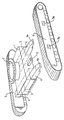
- numeral 1 designates the central body of the vehicle.
- the top of the vehicle has known means for attachment to the machine (not shown) that is mounted on top of the crawler track vehicle.
- Two crawler track sides 5 are mounted to the longitudinal sides of the central body 1.
- the central body incorporates guide means, schematically designated at 3, along which there are slidably mounted transverse beams 4, two for each crawler track side 5. Sliding movement of beams 4 is accomplished by driving means of known kind, for example hydraulic cylinders (not shown for simplicity) securely mounted to the central body 1, preferably within said body.
- the outer end portions 4a of the retractable beams 4 are adapted to be inserted and releasably locked, preferably in quick manner, in corresponding locking seats 5a obtained in the crawler track sides 5. Locking action may be effected exploiting hydraulically or electrically operated movable members (not shown) at the end portions 4a adapted for engaging in seats 5a.
- Disassembly of crawler track sides 5 is accomplished without having to detach the retractable beams 4. These beams are withdrawn inside the central body 1 to reduce bulk during transportation. It will be appreciated that this provision allows to leave the beam driving means permanently connected. Furthermore, mounting of the crawler track sides to the beam ends 4a is rapid and allows to skip the conventional operation of inserting the beams in the relevant sliding seats. In addition, there are fewer possibilities of errors as manual intervention is reduced.
- a transverse spacing member schematically designated at 6 can be mounted to the vehicle central body 1 (or, alternatively, to the crawler track sides 5) at an interposed position between the central body and each of the crawler track sides. In retracting the crawler track sides for transportation, said spacing members act as stopping means for the corresponding crawler track sides to detach same from the beams 4.
- the present solution provides for:
- the width attained by the sole retraction will suffice to fall within the prescribed loading gauge. If not, the sole retraction will allow transportation under exceptional conditions, whereas disassembly will allow transportation within the maximum loading gauge, or disassembly will permit transportation classified as exceptional as to the size but not the weight.
Landscapes
- Engineering & Computer Science (AREA)
- Mechanical Engineering (AREA)
- Chemical & Material Sciences (AREA)
- Combustion & Propulsion (AREA)
- Transportation (AREA)
- Handcart (AREA)
- Soil Working Implements (AREA)
- Jib Cranes (AREA)
- Vehicle Cleaning, Maintenance, Repair, Refitting, And Outriggers (AREA)
- Body Structure For Vehicles (AREA)
Claims (5)
- Gleitkettenfahrzeug mit einziehbaren Seitenteilen (5) der Art, das einen Hauptkörper (1) umfasst, der mit Antriebseinrichtungen zum gleitenden Bewegen einer Mehrzahl von einziehbaren, querliegenden Trägern (4) ausgestattet ist, die jeweils einen Endbereich (4a) aufweisen, der sicher an einem Gleitkettenseitenteil (5) befestigt ist,
dadurch gekennzeichnet, dass
die Endbereiche (4a) mit Mitteln zur lösbaren Verbindung mit entsprechenden Lagern (5a) versehen sind, die in den Gleitkettenseitenteilen (5) vorgesehen sind, wobei das Gleitkettenfahrzeug in einen passiven Zustand bzw. Transportzustand versetzt werden kann, in dem die Träger nach der Innenseite des Hauptkörpers (1) mittels der Antriebseinrichtungen eingezogen und
die Gleitkettenseitenteile (5) von den Trägern (4) abgenommen werden. - Gleitkettenfahrzeug nach Anspruch 1,
dadurch gekennzeichnet, dass
die lösbaren Verbindungsmittel hydraulisch oder elektrisch betriebene Schnellverbindungsmittel sind. - Gleitkettenfahrzeug nach Anspruch 1,
dadurch gekennzeichnet, dass
die mit den Trägern (4) verbundenen Antriebseinrichtungen auch während des Transportes verbunden bleiben. - Gleitkettenfahrzeug nach Anspruch 1,
dadurch gekennzeichnet, dass
die einziehbaren Träger (4) in den Führungen (3), die in dem Hauptkörper (1) des Gleitkettenfahrzeuges eingebaut sind, auch während des Transportes in Eingriff verbleiben. - Gleitkettenfahrzeug nach Anspruch 1,
dadurch gekennzeichnet, dass
es mindestens einen querliegenden Abstandshalter (6) umfasst, der zwischen dem Hauptkörper (1) des Fahrzeuges und jeweils dem Gleitkettenseitenteil (5) angeordnet ist, wobei der Abstandshalter als ein Anschlagsmittel dient, um das Gleitkettenseitenteil anzuhalten und um sein automatisches Abnehmen auszuführen, wenn es eingezogen wird.
Applications Claiming Priority (2)
| Application Number | Priority Date | Filing Date | Title |
|---|---|---|---|
| IT96TO000329A IT1285855B1 (it) | 1996-04-24 | 1996-04-24 | Carro cingolato a fiancate retrattili e smontabili. |
| ITTO960329 | 1996-04-24 |
Publications (2)
| Publication Number | Publication Date |
|---|---|
| EP0803428A1 EP0803428A1 (de) | 1997-10-29 |
| EP0803428B1 true EP0803428B1 (de) | 2002-07-03 |
Family
ID=11414579
Family Applications (1)
| Application Number | Title | Priority Date | Filing Date |
|---|---|---|---|
| EP97105912A Revoked EP0803428B1 (de) | 1996-04-24 | 1997-04-10 | Gleiskettenfahrzeug mit einziehbaren und abnehmbaren Seitenteilen |
Country Status (7)
| Country | Link |
|---|---|
| EP (1) | EP0803428B1 (de) |
| JP (1) | JPH1045057A (de) |
| KR (1) | KR100440766B1 (de) |
| AT (1) | ATE220021T1 (de) |
| DE (1) | DE69713672T2 (de) |
| ES (1) | ES2179234T3 (de) |
| IT (1) | IT1285855B1 (de) |
Families Citing this family (11)
| Publication number | Priority date | Publication date | Assignee | Title |
|---|---|---|---|---|
| FR2792901B1 (fr) * | 1999-04-28 | 2001-07-13 | Materiels Tech Ind Soc D | Plate-forme de propulsion modulaire et vehicule constitue a partir d'au moins une telle plate-forme |
| DE10200175A1 (de) * | 2002-01-04 | 2003-07-24 | Bauer Maschinen Gmbh | Raupenfahrwerk |
| US8256540B1 (en) * | 2011-03-29 | 2012-09-04 | Tadano Ltd. | Self-storing retainer cap assembly |
| DE102011102110B4 (de) * | 2011-05-20 | 2023-05-17 | Liebherr-Werk Ehingen Gmbh | Unterwagen für Raupenkran, Raupenkran und Verfahren zum Auf- und Abbau eines Raupenkrans |
| GB2504135A (en) | 2012-07-20 | 2014-01-22 | Bamford Excavators Ltd | Work Machine Chassis |
| WO2016095077A1 (zh) | 2014-12-15 | 2016-06-23 | 徐州重型机械有限公司 | 用于轮式起重机的履带挂接结构及轮式起重机 |
| CN104477792B (zh) * | 2014-12-15 | 2017-03-01 | 徐州重型机械有限公司 | 用于轮式起重机的履带挂接结构及轮式起重机 |
| DE202020101133U1 (de) * | 2020-03-02 | 2021-06-04 | Liebherr-Werk Nenzing Gmbh | Unterwagen für eine Arbeitsmaschine |
| CN113120102A (zh) * | 2021-05-28 | 2021-07-16 | 山西浩良感智矿山机电有限公司 | 组合式搬运车 |
| US11364959B1 (en) * | 2021-12-27 | 2022-06-21 | Amos Power, Inc. | Modular robotic vehicle |
| CN115783793A (zh) * | 2022-11-17 | 2023-03-14 | 金华电力设计院有限公司 | 一种适用于塔基施工设备的模块化堆叠运输方法 |
Family Cites Families (5)
| Publication number | Priority date | Publication date | Assignee | Title |
|---|---|---|---|---|
| US3037571A (en) * | 1959-08-17 | 1962-06-05 | Schield Bantam Company | Wide base crawler |
| DE1172549B (de) * | 1961-04-12 | 1964-06-18 | Hans Nolte | Vorrichtung zur Spurweitenveraenderung der Lauf- oder Kettenraeder nicht schienen-gebundener Fahrzeuge |
| US3696879A (en) * | 1969-05-31 | 1972-10-10 | Komatsu Mfg Co Ltd | Heavy bulldozer |
| US3712398A (en) * | 1970-03-19 | 1973-01-23 | Orenstein & Koppel Ag | Hydraulically operable device for changing the track width of track-laying vehicles |
| DE2047480C3 (de) * | 1970-09-26 | 1979-02-08 | Harnischfeger Gmbh, 4600 Dortmund | Kranunterwagen mit Raupenfahrwerk |
-
1996
- 1996-04-24 IT IT96TO000329A patent/IT1285855B1/it active IP Right Grant
-
1997
- 1997-04-10 AT AT97105912T patent/ATE220021T1/de not_active IP Right Cessation
- 1997-04-10 ES ES97105912T patent/ES2179234T3/es not_active Expired - Lifetime
- 1997-04-10 DE DE69713672T patent/DE69713672T2/de not_active Expired - Fee Related
- 1997-04-10 EP EP97105912A patent/EP0803428B1/de not_active Revoked
- 1997-04-21 KR KR1019970014659A patent/KR100440766B1/ko not_active Expired - Fee Related
- 1997-04-23 JP JP9106396A patent/JPH1045057A/ja not_active Withdrawn
Also Published As
| Publication number | Publication date |
|---|---|
| EP0803428A1 (de) | 1997-10-29 |
| ITTO960329A1 (it) | 1997-10-24 |
| KR100440766B1 (ko) | 2004-10-26 |
| IT1285855B1 (it) | 1998-06-24 |
| ITTO960329A0 (it) | 1996-04-24 |
| JPH1045057A (ja) | 1998-02-17 |
| ATE220021T1 (de) | 2002-07-15 |
| ES2179234T3 (es) | 2003-01-16 |
| KR970069859A (ko) | 1997-11-07 |
| DE69713672T2 (de) | 2002-12-05 |
| DE69713672D1 (de) | 2002-08-08 |
Similar Documents
| Publication | Publication Date | Title |
|---|---|---|
| US5163537A (en) | Battery changing system for electric battery-powered vehicles | |
| EP0803428B1 (de) | Gleiskettenfahrzeug mit einziehbaren und abnehmbaren Seitenteilen | |
| US4358133A (en) | Adjustable width trailer | |
| US4060145A (en) | Lift bed trailer suspension subframe | |
| US2756073A (en) | Transportable half flat-carload container convertible to semi-trailer | |
| US4091935A (en) | Crane with a pivotal assembly for detachably connecting and supporting a boom thereon | |
| FI60827C (fi) | Anordning foer oeverfoering av lastbaerare fraon en jaernvaegsvagn till en lastbil och vice versa | |
| HK44689A (en) | Recovery and towing vehicle | |
| EP3453671B1 (de) | Gabelstapler für den lufttransport und stauverfahren | |
| US6032809A (en) | Apparatus for reducing the axle load of a multiaxle movable telescopic crane | |
| US2091343A (en) | Material handling equipment | |
| FI79985C (fi) | Lyfttransportvagn. | |
| US4474359A (en) | Heavy duty lift bed trailer | |
| EP0103434A2 (de) | Abstützauslegervorrichtung für ein Fahrzeug und eine Methode zum Abstützen eines Fahrzeugs | |
| FI74663C (fi) | Anordning vid en lastbaerare samt anordning foer oeverfoering av lastbaeraren fraon en jaernvaegsvagn till en lastbil och omvaent. | |
| DE60202418T2 (de) | Auslegerbefestigungsstruktur eines Ladefahrzeugs | |
| US5165840A (en) | Clamp attachment for a lift truck | |
| EP0515470A1 (de) | Zusätzliche aufbausysteme für lastfahrzeuge. | |
| GB2268135A (en) | A load carrying road vehicle. | |
| US4344732A (en) | System for handling heavy and unwieldy vehicles | |
| US4824316A (en) | Transport system | |
| FI60829C (fi) | Foerfarande foer lastning av en fordons slaepvagn och ett med slaepvagn foersett fordon foer utfoerande av foerfarandet | |
| EP0158537A2 (de) | Auf einem Anhänger angeordnete Transporteinrichtung | |
| WO2000041912A1 (en) | Aircraft loading and unloading vehicle | |
| CN109592573B (zh) | 起重机 |
Legal Events
| Date | Code | Title | Description |
|---|---|---|---|
| PUAI | Public reference made under article 153(3) epc to a published international application that has entered the european phase |
Free format text: ORIGINAL CODE: 0009012 |
|
| AK | Designated contracting states |
Kind code of ref document: A1 Designated state(s): AT BE DE ES FR GB IT |
|
| 17P | Request for examination filed |
Effective date: 19971126 |
|
| GRAG | Despatch of communication of intention to grant |
Free format text: ORIGINAL CODE: EPIDOS AGRA |
|
| 17Q | First examination report despatched |
Effective date: 20011017 |
|
| GRAG | Despatch of communication of intention to grant |
Free format text: ORIGINAL CODE: EPIDOS AGRA |
|
| GRAH | Despatch of communication of intention to grant a patent |
Free format text: ORIGINAL CODE: EPIDOS IGRA |
|
| GRAH | Despatch of communication of intention to grant a patent |
Free format text: ORIGINAL CODE: EPIDOS IGRA |
|
| GRAA | (expected) grant |
Free format text: ORIGINAL CODE: 0009210 |
|
| AK | Designated contracting states |
Kind code of ref document: B1 Designated state(s): AT BE DE ES FR GB IT |
|
| REF | Corresponds to: |
Ref document number: 220021 Country of ref document: AT Date of ref document: 20020715 Kind code of ref document: T |
|
| REF | Corresponds to: |
Ref document number: 69713672 Country of ref document: DE Date of ref document: 20020808 |
|
| ET | Fr: translation filed | ||
| REG | Reference to a national code |
Ref country code: ES Ref legal event code: FG2A Ref document number: 2179234 Country of ref document: ES Kind code of ref document: T3 |
|
| PGFP | Annual fee paid to national office [announced via postgrant information from national office to epo] |
Ref country code: GB Payment date: 20030207 Year of fee payment: 7 |
|
| PGFP | Annual fee paid to national office [announced via postgrant information from national office to epo] |
Ref country code: BE Payment date: 20030305 Year of fee payment: 7 |
|
| PGFP | Annual fee paid to national office [announced via postgrant information from national office to epo] |
Ref country code: ES Payment date: 20030402 Year of fee payment: 7 |
|
| PLBI | Opposition filed |
Free format text: ORIGINAL CODE: 0009260 |
|
| PLBQ | Unpublished change to opponent data |
Free format text: ORIGINAL CODE: EPIDOS OPPO |
|
| PLAV | Examination of admissibility of opposition |
Free format text: ORIGINAL CODE: EPIDOS OPEX |
|
| PLBQ | Unpublished change to opponent data |
Free format text: ORIGINAL CODE: EPIDOS OPPO |
|
| PLBI | Opposition filed |
Free format text: ORIGINAL CODE: 0009260 |
|
| PLAV | Examination of admissibility of opposition |
Free format text: ORIGINAL CODE: EPIDOS OPEX |
|
| PGFP | Annual fee paid to national office [announced via postgrant information from national office to epo] |
Ref country code: FR Payment date: 20030424 Year of fee payment: 7 Ref country code: AT Payment date: 20030424 Year of fee payment: 7 |
|
| PLBF | Reply of patent proprietor to notice(s) of opposition |
Free format text: ORIGINAL CODE: EPIDOS OBSO |
|
| 26 | Opposition filed |
Opponent name: CASAGRANDE SPA Effective date: 20030331 |
|
| 26 | Opposition filed |
Opponent name: BAUER MASCHINEN GMBH Effective date: 20030401 Opponent name: CASAGRANDE SPA Effective date: 20030331 |
|
| PGFP | Annual fee paid to national office [announced via postgrant information from national office to epo] |
Ref country code: DE Payment date: 20030627 Year of fee payment: 7 |
|
| PLAX | Notice of opposition and request to file observation + time limit sent |
Free format text: ORIGINAL CODE: EPIDOSNOBS2 |
|
| PG25 | Lapsed in a contracting state [announced via postgrant information from national office to epo] |
Ref country code: GB Free format text: LAPSE BECAUSE OF NON-PAYMENT OF DUE FEES Effective date: 20040410 Ref country code: AT Free format text: LAPSE BECAUSE OF NON-PAYMENT OF DUE FEES Effective date: 20040410 |
|
| PG25 | Lapsed in a contracting state [announced via postgrant information from national office to epo] |
Ref country code: BE Free format text: LAPSE BECAUSE OF NON-PAYMENT OF DUE FEES Effective date: 20040430 |
|
| BERE | Be: lapsed |
Owner name: *SOILMEC S.P.A. Effective date: 20040430 |
|
| PG25 | Lapsed in a contracting state [announced via postgrant information from national office to epo] |
Ref country code: DE Free format text: LAPSE BECAUSE OF NON-PAYMENT OF DUE FEES Effective date: 20041103 |
|
| GBPC | Gb: european patent ceased through non-payment of renewal fee |
Effective date: 20040410 |
|
| RDAF | Communication despatched that patent is revoked |
Free format text: ORIGINAL CODE: EPIDOSNREV1 |
|
| REG | Reference to a national code |
Ref country code: FR Ref legal event code: ST |
|
| PLAQ | Examination of admissibility of opposition: information related to despatch of communication + time limit deleted |
Free format text: ORIGINAL CODE: EPIDOSDOPE2 |
|
| PLAR | Examination of admissibility of opposition: information related to receipt of reply deleted |
Free format text: ORIGINAL CODE: EPIDOSDOPE4 |
|
| PLBQ | Unpublished change to opponent data |
Free format text: ORIGINAL CODE: EPIDOS OPPO |
|
| RDAG | Patent revoked |
Free format text: ORIGINAL CODE: 0009271 |
|
| STAA | Information on the status of an ep patent application or granted ep patent |
Free format text: STATUS: PATENT REVOKED |
|
| 27W | Patent revoked |
Effective date: 20041218 |