EP0516093B1 - Installation frigorifique - Google Patents
Installation frigorifique Download PDFInfo
- Publication number
- EP0516093B1 EP0516093B1 EP92108965A EP92108965A EP0516093B1 EP 0516093 B1 EP0516093 B1 EP 0516093B1 EP 92108965 A EP92108965 A EP 92108965A EP 92108965 A EP92108965 A EP 92108965A EP 0516093 B1 EP0516093 B1 EP 0516093B1
- Authority
- EP
- European Patent Office
- Prior art keywords
- weight
- temperature side
- refrigerant
- refrigerant circuit
- refrigerating unit
- Prior art date
- Legal status (The legal status is an assumption and is not a legal conclusion. Google has not performed a legal analysis and makes no representation as to the accuracy of the status listed.)
- Expired - Lifetime
Links
- 239000003507 refrigerant Substances 0.000 claims description 131
- 239000000203 mixture Substances 0.000 claims description 35
- VOPWNXZWBYDODV-UHFFFAOYSA-N Chlorodifluoromethane Chemical compound FC(F)Cl VOPWNXZWBYDODV-UHFFFAOYSA-N 0.000 claims description 26
- XPDWGBQVDMORPB-UHFFFAOYSA-N Fluoroform Chemical compound FC(F)F XPDWGBQVDMORPB-UHFFFAOYSA-N 0.000 claims description 16
- UMNKXPULIDJLSU-UHFFFAOYSA-N dichlorofluoromethane Chemical compound FC(Cl)Cl UMNKXPULIDJLSU-UHFFFAOYSA-N 0.000 claims description 12
- 229940099364 dichlorofluoromethane Drugs 0.000 claims description 12
- RWRIWBAIICGTTQ-UHFFFAOYSA-N difluoromethane Chemical compound FCF RWRIWBAIICGTTQ-UHFFFAOYSA-N 0.000 claims description 12
- VNWKTOKETHGBQD-UHFFFAOYSA-N methane Chemical compound C VNWKTOKETHGBQD-UHFFFAOYSA-N 0.000 claims description 12
- BHNZEZWIUMJCGF-UHFFFAOYSA-N 1-chloro-1,1-difluoroethane Chemical compound CC(F)(F)Cl BHNZEZWIUMJCGF-UHFFFAOYSA-N 0.000 claims description 10
- XKRFYHLGVUSROY-UHFFFAOYSA-N Argon Chemical compound [Ar] XKRFYHLGVUSROY-UHFFFAOYSA-N 0.000 claims description 10
- WMIYKQLTONQJES-UHFFFAOYSA-N hexafluoroethane Chemical compound FC(F)(F)C(F)(F)F WMIYKQLTONQJES-UHFFFAOYSA-N 0.000 claims description 8
- QYSGYZVSCZSLHT-UHFFFAOYSA-N octafluoropropane Chemical compound FC(F)(F)C(F)(F)C(F)(F)F QYSGYZVSCZSLHT-UHFFFAOYSA-N 0.000 claims description 8
- 229960004065 perflutren Drugs 0.000 claims description 8
- IJGRMHOSHXDMSA-UHFFFAOYSA-N Atomic nitrogen Chemical compound N#N IJGRMHOSHXDMSA-UHFFFAOYSA-N 0.000 claims description 7
- GTLACDSXYULKMZ-UHFFFAOYSA-N pentafluoroethane Chemical compound FC(F)C(F)(F)F GTLACDSXYULKMZ-UHFFFAOYSA-N 0.000 claims description 6
- 229910052786 argon Inorganic materials 0.000 claims description 5
- TXEYQDLBPFQVAA-UHFFFAOYSA-N tetrafluoromethane Chemical compound FC(F)(F)F TXEYQDLBPFQVAA-UHFFFAOYSA-N 0.000 claims description 5
- 230000000694 effects Effects 0.000 claims description 4
- 229910052757 nitrogen Inorganic materials 0.000 claims description 3
- 239000003921 oil Substances 0.000 description 23
- 239000007788 liquid Substances 0.000 description 18
- 238000001704 evaporation Methods 0.000 description 17
- 230000008020 evaporation Effects 0.000 description 15
- 238000009835 boiling Methods 0.000 description 12
- 239000003638 chemical reducing agent Substances 0.000 description 11
- 239000012808 vapor phase Substances 0.000 description 9
- 238000007599 discharging Methods 0.000 description 6
- 238000007789 sealing Methods 0.000 description 6
- 230000001105 regulatory effect Effects 0.000 description 5
- 239000007791 liquid phase Substances 0.000 description 4
- 238000002156 mixing Methods 0.000 description 4
- CBENFWSGALASAD-UHFFFAOYSA-N Ozone Chemical compound [O-][O+]=O CBENFWSGALASAD-UHFFFAOYSA-N 0.000 description 3
- 230000006866 deterioration Effects 0.000 description 3
- 230000009977 dual effect Effects 0.000 description 3
- 238000002474 experimental method Methods 0.000 description 3
- 238000004880 explosion Methods 0.000 description 3
- 239000010802 sludge Substances 0.000 description 3
- XLYOFNOQVPJJNP-UHFFFAOYSA-N water Substances O XLYOFNOQVPJJNP-UHFFFAOYSA-N 0.000 description 3
- 239000010687 lubricating oil Substances 0.000 description 2
- 239000012071 phase Substances 0.000 description 2
- 230000002265 prevention Effects 0.000 description 2
- QVGXLLKOCUKJST-UHFFFAOYSA-N atomic oxygen Chemical compound [O] QVGXLLKOCUKJST-UHFFFAOYSA-N 0.000 description 1
- 239000008280 blood Substances 0.000 description 1
- 210000004369 blood Anatomy 0.000 description 1
- RJCQBQGAPKAMLL-UHFFFAOYSA-N bromotrifluoromethane Chemical compound FC(F)(F)Br RJCQBQGAPKAMLL-UHFFFAOYSA-N 0.000 description 1
- 238000001816 cooling Methods 0.000 description 1
- 230000008878 coupling Effects 0.000 description 1
- 238000010168 coupling process Methods 0.000 description 1
- 238000005859 coupling reaction Methods 0.000 description 1
- 229910001873 dinitrogen Inorganic materials 0.000 description 1
- 230000007613 environmental effect Effects 0.000 description 1
- 239000008246 gaseous mixture Substances 0.000 description 1
- 238000010438 heat treatment Methods 0.000 description 1
- 230000001050 lubricating effect Effects 0.000 description 1
- 238000002844 melting Methods 0.000 description 1
- 230000008018 melting Effects 0.000 description 1
- 238000000034 method Methods 0.000 description 1
- 239000003595 mist Substances 0.000 description 1
- 230000004048 modification Effects 0.000 description 1
- 238000012986 modification Methods 0.000 description 1
- 239000001301 oxygen Substances 0.000 description 1
- 229910052760 oxygen Inorganic materials 0.000 description 1
- 238000004321 preservation Methods 0.000 description 1
- 238000005057 refrigeration Methods 0.000 description 1
- 238000009834 vaporization Methods 0.000 description 1
- 230000008016 vaporization Effects 0.000 description 1
Images
Classifications
-
- C—CHEMISTRY; METALLURGY
- C09—DYES; PAINTS; POLISHES; NATURAL RESINS; ADHESIVES; COMPOSITIONS NOT OTHERWISE PROVIDED FOR; APPLICATIONS OF MATERIALS NOT OTHERWISE PROVIDED FOR
- C09K—MATERIALS FOR MISCELLANEOUS APPLICATIONS, NOT PROVIDED FOR ELSEWHERE
- C09K5/00—Heat-transfer, heat-exchange or heat-storage materials, e.g. refrigerants; Materials for the production of heat or cold by chemical reactions other than by combustion
- C09K5/02—Materials undergoing a change of physical state when used
- C09K5/04—Materials undergoing a change of physical state when used the change of state being from liquid to vapour or vice versa
- C09K5/041—Materials undergoing a change of physical state when used the change of state being from liquid to vapour or vice versa for compression-type refrigeration systems
- C09K5/044—Materials undergoing a change of physical state when used the change of state being from liquid to vapour or vice versa for compression-type refrigeration systems comprising halogenated compounds
- C09K5/045—Materials undergoing a change of physical state when used the change of state being from liquid to vapour or vice versa for compression-type refrigeration systems comprising halogenated compounds containing only fluorine as halogen
-
- C—CHEMISTRY; METALLURGY
- C09—DYES; PAINTS; POLISHES; NATURAL RESINS; ADHESIVES; COMPOSITIONS NOT OTHERWISE PROVIDED FOR; APPLICATIONS OF MATERIALS NOT OTHERWISE PROVIDED FOR
- C09K—MATERIALS FOR MISCELLANEOUS APPLICATIONS, NOT PROVIDED FOR ELSEWHERE
- C09K5/00—Heat-transfer, heat-exchange or heat-storage materials, e.g. refrigerants; Materials for the production of heat or cold by chemical reactions other than by combustion
- C09K5/02—Materials undergoing a change of physical state when used
- C09K5/04—Materials undergoing a change of physical state when used the change of state being from liquid to vapour or vice versa
- C09K5/041—Materials undergoing a change of physical state when used the change of state being from liquid to vapour or vice versa for compression-type refrigeration systems
- C09K5/044—Materials undergoing a change of physical state when used the change of state being from liquid to vapour or vice versa for compression-type refrigeration systems comprising halogenated compounds
-
- F—MECHANICAL ENGINEERING; LIGHTING; HEATING; WEAPONS; BLASTING
- F25—REFRIGERATION OR COOLING; COMBINED HEATING AND REFRIGERATION SYSTEMS; HEAT PUMP SYSTEMS; MANUFACTURE OR STORAGE OF ICE; LIQUEFACTION SOLIDIFICATION OF GASES
- F25B—REFRIGERATION MACHINES, PLANTS OR SYSTEMS; COMBINED HEATING AND REFRIGERATION SYSTEMS; HEAT PUMP SYSTEMS
- F25B7/00—Compression machines, plants or systems, with cascade operation, i.e. with two or more circuits, the heat from the condenser of one circuit being absorbed by the evaporator of the next circuit
-
- F—MECHANICAL ENGINEERING; LIGHTING; HEATING; WEAPONS; BLASTING
- F25—REFRIGERATION OR COOLING; COMBINED HEATING AND REFRIGERATION SYSTEMS; HEAT PUMP SYSTEMS; MANUFACTURE OR STORAGE OF ICE; LIQUEFACTION SOLIDIFICATION OF GASES
- F25B—REFRIGERATION MACHINES, PLANTS OR SYSTEMS; COMBINED HEATING AND REFRIGERATION SYSTEMS; HEAT PUMP SYSTEMS
- F25B9/00—Compression machines, plants or systems, in which the refrigerant is air or other gas of low boiling point
- F25B9/002—Compression machines, plants or systems, in which the refrigerant is air or other gas of low boiling point characterised by the refrigerant
- F25B9/006—Compression machines, plants or systems, in which the refrigerant is air or other gas of low boiling point characterised by the refrigerant the refrigerant containing more than one component
-
- C—CHEMISTRY; METALLURGY
- C09—DYES; PAINTS; POLISHES; NATURAL RESINS; ADHESIVES; COMPOSITIONS NOT OTHERWISE PROVIDED FOR; APPLICATIONS OF MATERIALS NOT OTHERWISE PROVIDED FOR
- C09K—MATERIALS FOR MISCELLANEOUS APPLICATIONS, NOT PROVIDED FOR ELSEWHERE
- C09K2205/00—Aspects relating to compounds used in compression type refrigeration systems
- C09K2205/10—Components
- C09K2205/12—Hydrocarbons
- C09K2205/122—Halogenated hydrocarbons
-
- C—CHEMISTRY; METALLURGY
- C09—DYES; PAINTS; POLISHES; NATURAL RESINS; ADHESIVES; COMPOSITIONS NOT OTHERWISE PROVIDED FOR; APPLICATIONS OF MATERIALS NOT OTHERWISE PROVIDED FOR
- C09K—MATERIALS FOR MISCELLANEOUS APPLICATIONS, NOT PROVIDED FOR ELSEWHERE
- C09K2205/00—Aspects relating to compounds used in compression type refrigeration systems
- C09K2205/10—Components
- C09K2205/12—Hydrocarbons
- C09K2205/128—Perfluorinated hydrocarbons
-
- C—CHEMISTRY; METALLURGY
- C09—DYES; PAINTS; POLISHES; NATURAL RESINS; ADHESIVES; COMPOSITIONS NOT OTHERWISE PROVIDED FOR; APPLICATIONS OF MATERIALS NOT OTHERWISE PROVIDED FOR
- C09K—MATERIALS FOR MISCELLANEOUS APPLICATIONS, NOT PROVIDED FOR ELSEWHERE
- C09K2205/00—Aspects relating to compounds used in compression type refrigeration systems
- C09K2205/10—Components
- C09K2205/13—Inert gases
-
- F—MECHANICAL ENGINEERING; LIGHTING; HEATING; WEAPONS; BLASTING
- F25—REFRIGERATION OR COOLING; COMBINED HEATING AND REFRIGERATION SYSTEMS; HEAT PUMP SYSTEMS; MANUFACTURE OR STORAGE OF ICE; LIQUEFACTION SOLIDIFICATION OF GASES
- F25B—REFRIGERATION MACHINES, PLANTS OR SYSTEMS; COMBINED HEATING AND REFRIGERATION SYSTEMS; HEAT PUMP SYSTEMS
- F25B2400/00—General features or devices for refrigeration machines, plants or systems, combined heating and refrigeration systems or heat-pump systems, i.e. not limited to a particular subgroup of F25B
- F25B2400/12—Inflammable refrigerants
Definitions
- the present invention relates to a refrigerating unit of a binary refrigerating system comprising independent dual refrigerant circuit, wherein an evaporator of a high temperature side refrigerant circuit and a condenser of a low temperature side refrigerant circuit form a thermal exchanger.
- each refrigerant circuit in the high temperature side and low temperature side comprises independent dual refrigerant closed-circuit, and an evaporator of the high temperature side refrigerant circuit and a condenser of the low temperature side refrigerant circuit form a thermal exchanger so that the refrigerant of the low temperature side refrigerant circuit is condensed by the evaporation of the refrigerant of the high temperature side refrigerant circuit.
- refrigerant having lower boiling point (evaporation temperature) to the low temperature side refrigerant circuit, it is possible to obtain an extremely low temperature by the evaporator of the low temperature side refrigerant circuit.
- the applicant of the present invention disclosed the above mentioned latter method, that is, the way of realizing a super low temperature of -130°C by improving the sealing refrigerant composition in the specification of the Japanese Patent Application No. 61-91599 (published as Japanese Patent Application No. 62-248963) which was filed prior to the present case.
- R500 or R502 are sealed into the high temperature side refrigerant circuit and R13B1 (bromotrifluoromethane) or R503 are sealed into the low temperature side refrigerant circuit, respectively.
- the refrigerants such as R500, R502, R13B1, and R503 are the refrigerants which are the object of a regulated flon and it has been studied to replace to the refrigerant out of the regulated immediately from the viewpoint of an environmental protection of an ozone layer destroy and so on.
- GB-A-2180921 discloses a refrigeration system comprising a cascaded system having a high temperature refrigerant circuit and a low temperature refrigerant circuit comprising a non-azeotropic mixture.
- this refrigerating unit is mainly used for keeping an organism such as blood and an examined body for long time in a biotechnology field, the unit for realizing the lower temperature, for example,-150°C has been required from the viewpoint of the reliability.
- the present invention is to solve the above problems, and the object of the present invention is to provide an excellent refrigerating unit for realizing the super lower temperature of -150°C without any usage of the refrigerant which is the object of the regulated flon and a liquid nitrogen.
- the present invention provides a refrigerating unit comprising a high temperature side refrigerant circuit and a low temperature side refrigerant circuit for forming an independent refrigerant closed-circuit which exhibits a refrigerating effect by that a refrigerant discharged from a compressor is condensed and then is evaporated, and an evaporator of said high temperature side refrigerant circuit and a condenser of said low temperature side refrigerant circuit form a thermal exchanger, characterized in that a non-azeotropic mixture refrigerant comprising;
- another non-azeotropic mixture refrigerant comprising chlorodifluoromethane, 1-chloro-1, 1-difluoroethane, and dichlorofluoromethane is sealed into said high temperature side refrigerant circuit.
- the non-azeotropic mixture refrigerant sealed into the high temperature side refrigerant circuit comprises 70% by weight of chlorodifluoromethane, 25% by weight of 1-chloro-1, 1-difluoroethane, and 5% by weight of dichlorofluoromethane.
- another non-azeotropic mixture refrigerant comprising chlorodifluoromethane, 1-chloro-1, 1-difluoroethane, octafluoropropane, is sealed into the high temperature side refrigerant circuit.
- the non-azeotropic mixture refrigerant sealed into the high temperature side refrigerant circuit comprises 70% by weight of chlorodifluoromethane, 25% by weight of 1-chloro-1, 1-difluoroethane, and 5% by weight of octafluoropropane.
- octafluoropropane is added to the non-azeotropic mixture refrigerant sealed into the low temperature side refrigerant circuit.
- (d) component is chlorodifluoromethane.
- (d) component is difluoromethane.
- (e) component is a mixture of trifluoromethane and hexafluoroethane.
- (e) component is trifluoromethane.
- the present invention realizes the super low temperature of -150°C in the final step of the evaporator without any usage of the refrigerant which is the object of the regulated flon by using the difference of the evaporation temperature of each refrigerant and by condensing the refrigerant still in the vapor phase state subsequently by plural thermal exchangers. As a result of that, it is possible to cope with the problem of the ozone layer destroy and to stabilize the keeping of the organism and the examined body for long time.
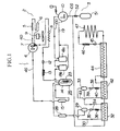
- Fig. 1 is a view for showing the refrigerant circuit of the refrigerating unit according to the embodiment of the present invention.
- Fig. 1 shows the refrigerant circuit (1) of the refrigerating unit of the present invention.
- the refrigerant circuit (1) comprises each independent high temperature side refrigerant circuit (2) as a first refrigerant closed-circuit and the low temperature side refrigerant circuit (3) as a second refrigerant closed-circuit.
- the reference numeral (4) is an electric compressor for forming the high temperature side refrigerant circuit (2), which uses one phase or three phases AC power.
- a pipe (4D) in the discharging side of the electric compressor (4) is coupled to an auxiliary condenser (5) and this auxiliary condenser (5) is further coupled to a dew prevention pipe (6) for heating a opening frame of a stockroom of the refrigerator.
- this auxiliary compressor (5) is coupled to an oil cooler (7) of the electric compressor (4) and is coupled to a condenser (8) finally.
- (9) is an air blower for cooling the condenser (8).
- the refrigerant pipe from the condenser (8) passes through a dryer (12), then passes through an evaporator (14) as the evaporator portion for forming the evaporator through a pressure reducer (13), and is coupled to an accumulator (15) as a refrigerant receiver.
- the pipe from the accumulator (15) is coupled to a suction pipe (4S) of the electric compressor (4).
- refrigerant chlorodifluoromethane (R22), 1-chloro-1, 1-difluoroethane (R142b), and dichlorofluoromethane (R21) having each different boiling point are filled, and the composition thereof is, for example, 70% by weight of R22, 25% by weight of R142b, and 5% by weight of R21.
- the high temperature gaseous refrigerant discharged from the electric compressor (4) is condensed by the auxiliary condenser (5), dew prevention pipe (6), oil cooler (7) and condenser (8) and is radiated to liquefaction. Then, the water is removed by the dryer (12) and the resultant is pressure-reduced by the pressure reducer (13) and is poured into the evaporator (14) subsequently. So, the refrigerants R22 and R142b evaporate and a heat of vaporization is absorbed from circumference to cool the evaporator (14), and the resultant is fed back to the electric compressor (4) through the accumulator (15) as the refrigerant receiver.
- the ability of the electric compressor (4) is, for example, 1.5HP, and the final reached temperature of the evaporator (14) during the operation is -25°C to -35°C.
- R21 of the refrigerant has the boiling point of 8.95°C, R21 does not evaporate in the evaporator (14) and remains as the liquid state. Accordingly, although this does not contribute to the refrigerating at all, it has functions of performing feedback to the electric compressor (4) in the state of mixing the lubricating oil of the electric compressor and the water which can not be absorbed by the dryer (12) therein and of making the temperature of the compressor (4) low by the evaporation within the electric compressor (4) of the liquid refrigerant.
- a pipe (10D) in the discharging side of the electric compressor (10) form forming the low temperature side refrigerant circuit (3) is coupled by two stages of oil separators (18a) and (18b) which are coupled in serial.
- An oil return pipe (19) for returning to the electric compressor (10) is coupled from the oil separators (18a) and (18b).
- the refrigerant pipe from the oil separators (18a) and (18b) is coupled to a condense pipe (23) as the high pressure side pipe inserted into the evaporator (14).
- the evaporator (14) and the condense pipe (23) form a cascade condenser (25).
- the discharged pipe of the condense pipe (23) is coupled to a first vapor-liquid separator (29) through a dryer (28).
- a vapor phase pipe (30) from the vapor-liquid separator (29) passes through a first intermediate thermal exchanger (32) and is couple to a second vapor-liquid separator (33).
- a liquid phase pipe (34) from the vapor-liquid separator (29) passes through a dryer (35) and is coupled to the first intermediate thermal exchanger through a pressure reducer (36).
- a liquid phase pipe (38) from the vapor-liquid separator (33) passes through a dryer (39) and is coupled to a second intermediate thermal exchanger (42) through a pressure reducer (40).
- a vapor phase pipe (43) from the vapor-liquid separator (33) passes through the second intermediate thermal exchanger (42) and then passes through a third intermediate thermal exchanger (44), and is coupled to a pressure reducer (46) through a dryer (45).
- the pressure reducer (46) is coupled to an evaporating pipe (47) as the evaporator and the evaporation pipe (47) is coupled to the third intermediate thermal exchanger (44).
- the third intermediate thermal exchanger (44) is coupled to the second (42) and the first intermediate thermal exchanger (32) subsequently and is coupled to a suction pipe (10S) of the electric compressor (10).
- a mixture refrigerant having different boiling point is sealed into the low temperature side refrigerant circuit (3).
- Said mixture refrigerant comprises;
- the mixture refrigerant of R740 argon
- R50 methane
- R21 diichlorofluoromethane
- R14 tetrafluoromethane
- R22 chlorodifluoromethane
- R23 trifluoromethane
- each refrigerant is, for example, 12% by weight of R21, 38% by weight of R22, 16% by weight of R23, 23% by weight of R14, 5% by weight of R50, and 6% by weight of R740.
- R50 is methane and has a danger of causing the explosion by coupling with oxygen, by mixing with each flon refrigerant with the above mentioned ratio, there is no danger of explosion. Accordingly, even if any leakage accident of the mixture refrigerant occurs, there is no possibility to cause the explosion.
- the mixture refrigerant from the condense pipe (23) passes through the dryer (28) and is poured into the vapor-liquid separator (29).
- R14, R50, and R740 in the mixture refrigerant have the extremely low boiling point, they are not condensed and are still in the vapor state.
- One part of R21, R22, and R23 are condensed to liquefaction, and the mixture refrigerant is separated, that is R14, R50, and R740 are to the vapor phase pipe (30) and R21, R22, and R23 are to the liquid phase pipe (34).
- the mixture refrigerant poured into the vapor pipe (30) is condensed by the thermal exchange of the first intermediate thermal exchanger (32) and reaches at the vapor-liquid separator (33).
- the low temperature refrigerant fed back from the evaporation pipe (47) is poured into the first intermediate thermal exchanger (32). Further, after the liquid refrigerant poured into the liquid phase pipe (34) passes through the dryer (35) and pressure-reduced by the pressure reducer (36), it is poured into the first intermediate thermal exchanger (32) and is evaporated therein, thereby contributing to the refrigerating. Accordingly, when the one part of non-condensed R14, R50, R740, and R23 was refrigerated the intermediate temperature in the first intermediate thermal exchanger (32) became -56.4°C.
- R23 in the mixture refrigerant passed through the vapor-phase pipe (30) is condensed to liquefaction perfectly and is separated by the second vapor-liquid separator (33).
- R14, R50, and R740 are still in the vapor state because of the low boiling point.
- the water contents of R23 separated by the second vapor-liquid separator (33) is removed by the dryer (39) in the second intermediate thermal exchanger and the resultant is pressure-reduced by the pressure reducer (40). Then, it is poured into the second intermediate thermal exchanger (42) to refrigerate R14, R50, and R740 in the vapor-phase pipe (43) with the low temperature refrigerant which is fed back from the evaporation pipe (47). Thereby, R14 having highest evaporation temperature is condensed.
- the vapor phase pipe (43) passing through the second intermediate thermal exchanger (42) further passes through the third intermediate thermal exchanger (44).
- the refrigerant just discharged from the evaporator (47) is fed back.
- the intermediate temperature of the third intermediate thermal exchanger (44) became -109.8°C and the temperature around the entrance became -151.9°C, which was relatively low temperature.
- R50 and R740 in the vapor-phase pipe (43) is condensed.
- one part of the liquefied R14, R50, and R740 is pressure-reduced by the pressure reducer (46), it is poured into the evaporation pipe (47), thereby refrigerating the surroundings by evaporating.
- the refrigerant from the evaporation pipe (47) is poured into the third intermediate thermal exchanger (44), the second intermediate thermal exchanger (42), and the first intermediate thermal exchanger (32) subsequently, is mixed with the refrigerant evaporated in each thermal exchanger, and is fed back to the electric compressor (10) through the suction pipe (10S).
- the oil mixed with the refrigerant and is discharged from the electric compressor (10) is returned to the compressor (10) by separating in the oil separator (18a), (18b).
- the mist oil discharged from the oil separators (18a) and (18b) with the refrigerant is melted into R21 and R22 which have good compatibility with the oil and is returned to the compressor (10).
- R21 is fed back to the compressor (10) as it is in the liquid state and is evaporated within the compressor (10), thereby reducing the discharging temperature of the compressor (10).
- each refrigerant is not restricted to the above mentioned embodiment.
- the refrigerating unit according to claim 1 when the non-azeotropic mixture refrigerant comprises 3 to 13% by weight of argon, 3 to 13% by weight of methane, 0 to 32% by weight of dichlorofluoromethane, 15 to 45% by weight of tetrafluoromethane, 13 to 53% by weight of (d) component 10 to 36% by weight of (e) component, it was found to obtain the super low temperature about -150°C in the evaporation pipe (47).
- composition of 70% by weight of chlorodifluoromethane, 25% by weight of 1-chloro-1, 1-difluoroethane, and 5% by weight of octafluoropropane is added into the non-azeotropic mixture refrigerant sealed into the high temperature side refrigerant circuit, it is also possible to obtain the same effect.
- the present invention it is possible to realize the super low temperature of -150°C in the final step of the evaporator by using the difference of the evaporation temperature of each refrigerant and by condensing the refrigerant which is still in the vapor-phase state by plural thermal exchangers subsequently without any usage of the refrigerant which is the object of the regulated flon. As a result of that, it can cope with the problem of the ozone layer destroy and it is possible to stabilize the preservation of the organism and the examined body for long time.
Landscapes
- Engineering & Computer Science (AREA)
- Chemical & Material Sciences (AREA)
- Thermal Sciences (AREA)
- Physics & Mathematics (AREA)
- Materials Engineering (AREA)
- Combustion & Propulsion (AREA)
- Chemical Kinetics & Catalysis (AREA)
- Organic Chemistry (AREA)
- Mechanical Engineering (AREA)
- General Engineering & Computer Science (AREA)
- Lubricants (AREA)
- Organic Low-Molecular-Weight Compounds And Preparation Thereof (AREA)
- Devices That Are Associated With Refrigeration Equipment (AREA)
Claims (13)
- Groupe frigorifique comprenant un circuit de réfrigérant latéral à haute température et un circuit de réfrigérant latéral à basse température pour former un circuit fermé de réfrigérant indépendant qui présente un effet réfrigérant du fait qu'un réfrigérant déchargé d'un compresseur est condensé puis évaporé, et qu'un évaporateur dudit circuit de réfrigérant latéral à haute température et un condenseur dudit circuit de réfrigérant latéral à basse température forment un échangeur thermique, caractérisé en ce qu'un réfrigérant de mélange non-azéotrope comprenant :(a) 3 à 13 % en poids d'argon ;(b) 3 à 13 % en poids de méthane ;(c) 0 à 32 % en poids de dichlorofluorométhane et 15 à 45 % en poids de tétrafluorométhane ;(d) 13 à 53 % en poids de chlorodifluorométhane, de difluorométhane ou de pentafluoroéthane ; et(e) 10 à 36 % en poids de trifluorométhane et/ou d'hexafluoroéthane, est contenu de façon étanche dans ledit circuit de réfrigérant latéral à basse température.
- Groupe frigorifique selon la revendication 1, dans lequel un autre réfrigérant de mélange non-azéotrope comprenant du chlorodifluorométhane, du 1-chloro-1,1-difluoroéthane, et du dichlorofluorométhane est contenu de façon étanche dans ledit circuit de réfrigérant latéral à haute température.
- Groupe frigorifique selon la revendication 2, dans lequel le réfrigérant de mélange non-azéotrope contenu de façon étanche dans le circuit de réfrigérant latéral à haute température comprend 70 % en poids de chlorodifluorométhane, 25 % en poids de 1-chlore-1,1-difluoroéthane, et 5 % en poids de dichlorofluorométhane.
- Groupe frigorifique selon la revendication 1, dans lequel un autre réfrigérant de mélange non-azéotrope comprenant du chlorodifluorométhane, du 1-chloro-1,1-difluoroéthane, de l'octafluoropropane est contenu de façon étanche dans le circuit de réfrigérant latéral à haute température.
- Groupe frigorifique selon la revendication 4, dans lequel le réfrigérant de mélange non-azéotrope contenu de façon étanche dans le circuit de réfrigérant latéral à haute température comprend 70 % en poids de chlorodifluorométhane, 25 % en poids de 1-chlore-1,1-difluoroéthane, et 5 % en poids d'octafluoropropane.
- Groupe frigorifique selon la revendication 1, dans lequel l'octafluoropropane est ajouté au réfrigérant de mélange non-azéotrope contenu de façon étanche dans le circuit de réfrigérant latéral à basse température.
- Groupe frigorifique selon la revendication 1, dans lequel le composant (d) est le chlorodifluorométhane.
- Groupe frigorifique selon la revendication 1, dans lequel le composant (d) est le difluorométhane.
- Groupe frigorifique selon la revendication 1, dans lequel le composant (d) est le pentafluoroéthane.
- Groupe frigorifique selon la revendication 1, dans lequel le composant (e) est un mélange de trifluorométhane et d'hexafluoroéthane.
- Groupe frigorifique selon la revendication 1, dans lequel le composant (e) est le trifluorométhane.
- Groupe frigorifique selon la revendication 1, dans lequel le composant (e) est l'hexafluoroéthane.
- Groupe frigorifique selon la revendication 1, dans lequel de l'azote est ajouté au réfrigérant de mélange non-azéotrope contenu de façon étanche dans le circuit de réfrigérant latéral à basse température.
Applications Claiming Priority (2)
| Application Number | Priority Date | Filing Date | Title |
|---|---|---|---|
| JP123904/91 | 1991-05-28 | ||
| JP12390491A JP3208151B2 (ja) | 1991-05-28 | 1991-05-28 | 冷凍装置 |
Publications (2)
| Publication Number | Publication Date |
|---|---|
| EP0516093A1 EP0516093A1 (fr) | 1992-12-02 |
| EP0516093B1 true EP0516093B1 (fr) | 1996-04-24 |
Family
ID=14872222
Family Applications (1)
| Application Number | Title | Priority Date | Filing Date |
|---|---|---|---|
| EP92108965A Expired - Lifetime EP0516093B1 (fr) | 1991-05-28 | 1992-05-27 | Installation frigorifique |
Country Status (4)
| Country | Link |
|---|---|
| US (1) | US5265443A (fr) |
| EP (1) | EP0516093B1 (fr) |
| JP (1) | JP3208151B2 (fr) |
| DE (1) | DE69210093T2 (fr) |
Cited By (6)
| Publication number | Priority date | Publication date | Assignee | Title |
|---|---|---|---|---|
| US5784893A (en) * | 1994-03-30 | 1998-07-28 | Kabushiki Kaisha Toshiba | Air conditioning system with built-in intermediate heat exchanger with two different types of refrigerants circulated |
| US5801937A (en) * | 1996-10-16 | 1998-09-01 | American Superconductor Corporation | Uninterruptible power supplies having cooled components |
| AU698733B2 (en) * | 1994-07-27 | 1998-11-05 | Mexichem Amanco Holding, S.A. De C.V. | Refrigerant compositions |
| US6023934A (en) * | 1996-08-16 | 2000-02-15 | American Superconductor Corp. | Methods and apparatus for cooling systems for cryogenic power conversion electronics |
| US6173577B1 (en) | 1996-08-16 | 2001-01-16 | American Superconductor Corporation | Methods and apparatus for cooling systems for cryogenic power conversion electronics |
| WO2021121546A1 (fr) | 2019-12-16 | 2021-06-24 | Mainklima Gmbh | Système frigorifique à compression pour chambre frigorifique électrique |
Families Citing this family (41)
| Publication number | Priority date | Publication date | Assignee | Title |
|---|---|---|---|---|
| JP2764489B2 (ja) * | 1991-10-29 | 1998-06-11 | 株式会社荏原製作所 | 冷凍装置用冷媒及び該冷媒を用いる冷凍装置 |
| EP0846926A3 (fr) * | 1993-04-27 | 1999-04-28 | Mitsubishi Denki Kabushiki Kaisha | Système de circulation de frigorigène |
| TW354152U (en) * | 1993-04-27 | 1999-03-01 | Mitsubishi Electric Corp | Refrigerant circulating system |
| US5416247A (en) * | 1993-11-19 | 1995-05-16 | E. I. Du Pont De Nemours And Company | Chemical disposal of halocarbons |
| US5408848A (en) * | 1994-02-25 | 1995-04-25 | General Signal Corporation | Non-CFC autocascade refrigeration system |
| US5706663A (en) * | 1995-11-20 | 1998-01-13 | Apd Cryogenics, Inc. | High efficiency throttle cryogenic refrigerator based on one stage compressor |
| FR2755753B1 (fr) * | 1996-11-13 | 1998-12-31 | Armines | Melange frigorigene de type zeotrope sans derives chlores |
| DE19653244A1 (de) * | 1996-12-20 | 1998-06-25 | L & R Kaeltetechnik Gmbh | Kälteanlage |
| JP3361475B2 (ja) * | 1998-05-18 | 2003-01-07 | 松下電器産業株式会社 | 熱交換器 |
| US6105388A (en) * | 1998-12-30 | 2000-08-22 | Praxair Technology, Inc. | Multiple circuit cryogenic liquefaction of industrial gas |
| US6041620A (en) * | 1998-12-30 | 2000-03-28 | Praxair Technology, Inc. | Cryogenic industrial gas liquefaction with hybrid refrigeration generation |
| US6176102B1 (en) * | 1998-12-30 | 2001-01-23 | Praxair Technology, Inc. | Method for providing refrigeration |
| US6112550A (en) * | 1998-12-30 | 2000-09-05 | Praxair Technology, Inc. | Cryogenic rectification system and hybrid refrigeration generation |
| US6076372A (en) * | 1998-12-30 | 2000-06-20 | Praxair Technology, Inc. | Variable load refrigeration system particularly for cryogenic temperatures |
| US6327866B1 (en) * | 1998-12-30 | 2001-12-11 | Praxair Technology, Inc. | Food freezing method using a multicomponent refrigerant |
| US6041621A (en) * | 1998-12-30 | 2000-03-28 | Praxair Technology, Inc. | Single circuit cryogenic liquefaction of industrial gas |
| US6053008A (en) * | 1998-12-30 | 2000-04-25 | Praxair Technology, Inc. | Method for carrying out subambient temperature, especially cryogenic, separation using refrigeration from a multicomponent refrigerant fluid |
| CN100483040C (zh) | 2000-06-28 | 2009-04-29 | 布鲁克斯自动化公司 | 用于深度低温的制冷系统的混合制冷剂 |
| JP4569041B2 (ja) * | 2000-07-06 | 2010-10-27 | 株式会社デンソー | 車両用冷凍サイクル装置 |
| US6327865B1 (en) * | 2000-08-25 | 2001-12-11 | Praxair Technology, Inc. | Refrigeration system with coupling fluid stabilizing circuit |
| US7478540B2 (en) | 2001-10-26 | 2009-01-20 | Brooks Automation, Inc. | Methods of freezeout prevention and temperature control for very low temperature mixed refrigerant systems |
| US6532752B1 (en) | 2002-03-28 | 2003-03-18 | Praxair Technology, Inc. | Food freezing system |
| JP3478292B2 (ja) * | 2002-05-28 | 2003-12-15 | ダイキン工業株式会社 | 冷凍装置の圧縮機構 |
| JP3940840B2 (ja) * | 2002-11-22 | 2007-07-04 | ダイキン工業株式会社 | 空気調和装置 |
| US6631625B1 (en) * | 2002-11-27 | 2003-10-14 | Gsle Development Corporation (De Corp) | Non-HCFC refrigerant mixture for an ultra-low temperature refrigeration system |
| US20040124394A1 (en) * | 2002-11-27 | 2004-07-01 | Chuan Weng | Non-HCFC refrigerant mixture for an ultra-low temperature refrigeration system |
| CN100491864C (zh) * | 2002-12-03 | 2009-05-27 | 日本冷冻机株式会社 | 超低温用非共沸混合冷冻剂 |
| US20050103028A1 (en) * | 2003-11-13 | 2005-05-19 | Chuan Weng | Non-CFC refrigerant mixture for an ultra-low temperature refrigeration system |
| EP2818530B1 (fr) * | 2004-01-28 | 2020-01-01 | Edwards Vacuum, LLC | Cycle de réfrigération utilisant un mélange frigorigène de composant inerte |
| JP4420807B2 (ja) | 2004-12-14 | 2010-02-24 | 三洋電機株式会社 | 冷凍装置 |
| JP2007107858A (ja) * | 2005-10-17 | 2007-04-26 | Sanyo Electric Co Ltd | 冷凍装置 |
| JP2007303794A (ja) * | 2006-05-15 | 2007-11-22 | Sanyo Electric Co Ltd | 冷凍装置 |
| JP2007303792A (ja) * | 2006-05-15 | 2007-11-22 | Sanyo Electric Co Ltd | 冷凍装置 |
| JP5128424B2 (ja) * | 2008-09-10 | 2013-01-23 | パナソニックヘルスケア株式会社 | 冷凍装置 |
| ITRM20090654A1 (it) * | 2009-12-11 | 2011-06-12 | Eon Srl | Oli lubrificanti per motori diesel funzionanti con oli vegetali |
| CN102494429A (zh) * | 2011-12-08 | 2012-06-13 | 重庆翔源制冷设备有限公司 | 双级压缩一体化低温制冷机组 |
| GB2562509B (en) * | 2017-05-17 | 2020-04-29 | Mexichem Fluor Sa De Cv | Heat transfer compositions |
| JP6994419B2 (ja) * | 2018-03-29 | 2022-01-14 | 東京エレクトロン株式会社 | 冷却システム |
| CN108531135B (zh) | 2018-04-10 | 2021-05-07 | 龙志刚 | 适用于深冷温区的混合制冷剂及其制备方法、应用方法 |
| CN110668027A (zh) * | 2019-10-17 | 2020-01-10 | 浙江雪波蓝科技有限公司 | 单元冷藏配送箱 |
| WO2021083648A1 (fr) | 2019-10-30 | 2021-05-06 | Liconic Ag | Dispositif de stockage à basse température à haute efficacité |
Family Cites Families (13)
| Publication number | Priority date | Publication date | Assignee | Title |
|---|---|---|---|---|
| JPS5443215B1 (fr) * | 1970-06-03 | 1979-12-19 | ||
| US3733845A (en) * | 1972-01-19 | 1973-05-22 | D Lieberman | Cascaded multicircuit,multirefrigerant refrigeration system |
| FR2514875A1 (fr) * | 1981-10-19 | 1983-04-22 | Inst Francais Du Petrole | Procede de chauffage et/ou de conditionnement thermique d'un local au moyen d'une pompe a chaleur a compression utilisant un melange specifique de fluides de travail |
| IT1176290B (it) * | 1984-06-12 | 1987-08-18 | Snam Progetti | Processo per raffreddamento e liquefazione di gas a basso punto di ebollizione |
| GB2180921B (en) * | 1985-09-25 | 1990-01-24 | Sanyo Electric Co | Refrigeration system |
| DE3766355D1 (de) * | 1986-12-16 | 1991-01-03 | Systron Donner Corp | Kuehlmittel. |
| JPH01108292A (ja) * | 1987-10-19 | 1989-04-25 | Daikin Ind Ltd | 冷媒 |
| CA2003062C (fr) * | 1988-11-18 | 1998-09-29 | Kishio Yokouchi | Production et emploi de caloporteur pour dispositifs de cryogenie |
| JPH0660306B2 (ja) * | 1989-06-16 | 1994-08-10 | 三洋電機株式会社 | 冷媒組成物 |
| GB2244492B (en) * | 1989-09-12 | 1993-08-04 | Star Refrigeration | Three-component refrigerant mixture |
| US4978467A (en) * | 1989-09-26 | 1990-12-18 | Allied-Signal Inc. | Azeotrope-like compositions of pentafluoroethane and difluoromethane |
| JPH07104057B2 (ja) * | 1990-03-09 | 1995-11-13 | 三洋電機株式会社 | 二元冷凍装置 |
| US5092138A (en) * | 1990-07-10 | 1992-03-03 | The University Of Maryland | Refrigeration system |
-
1991
- 1991-05-28 JP JP12390491A patent/JP3208151B2/ja not_active Expired - Fee Related
-
1992
- 1992-05-27 US US07/889,529 patent/US5265443A/en not_active Expired - Fee Related
- 1992-05-27 EP EP92108965A patent/EP0516093B1/fr not_active Expired - Lifetime
- 1992-05-27 DE DE69210093T patent/DE69210093T2/de not_active Expired - Fee Related
Cited By (6)
| Publication number | Priority date | Publication date | Assignee | Title |
|---|---|---|---|---|
| US5784893A (en) * | 1994-03-30 | 1998-07-28 | Kabushiki Kaisha Toshiba | Air conditioning system with built-in intermediate heat exchanger with two different types of refrigerants circulated |
| AU698733B2 (en) * | 1994-07-27 | 1998-11-05 | Mexichem Amanco Holding, S.A. De C.V. | Refrigerant compositions |
| US6023934A (en) * | 1996-08-16 | 2000-02-15 | American Superconductor Corp. | Methods and apparatus for cooling systems for cryogenic power conversion electronics |
| US6173577B1 (en) | 1996-08-16 | 2001-01-16 | American Superconductor Corporation | Methods and apparatus for cooling systems for cryogenic power conversion electronics |
| US5801937A (en) * | 1996-10-16 | 1998-09-01 | American Superconductor Corporation | Uninterruptible power supplies having cooled components |
| WO2021121546A1 (fr) | 2019-12-16 | 2021-06-24 | Mainklima Gmbh | Système frigorifique à compression pour chambre frigorifique électrique |
Also Published As
| Publication number | Publication date |
|---|---|
| EP0516093A1 (fr) | 1992-12-02 |
| DE69210093D1 (de) | 1996-05-30 |
| US5265443A (en) | 1993-11-30 |
| JP3208151B2 (ja) | 2001-09-10 |
| DE69210093T2 (de) | 1996-09-19 |
| JPH04350471A (ja) | 1992-12-04 |
Similar Documents
| Publication | Publication Date | Title |
|---|---|---|
| EP0516093B1 (fr) | Installation frigorifique | |
| CN100439818C (zh) | 冷冻装置 | |
| JP3244296B2 (ja) | 冷媒組成物及びこれを使用した二元冷凍装置 | |
| CA2019096C (fr) | Composition frigorigene | |
| JP4651255B2 (ja) | 冷媒組成物およびそれを用いた冷凍回路 | |
| US20040124394A1 (en) | Non-HCFC refrigerant mixture for an ultra-low temperature refrigeration system | |
| KR960000866B1 (ko) | 냉매조성물 | |
| JPWO2001023494A1 (ja) | 冷媒組成物およびそれを用いた冷凍回路 | |
| JP3863831B2 (ja) | 冷媒組成物およびこの冷媒組成物を用いた冷凍回路 | |
| JPH0660306B2 (ja) | 冷媒組成物 | |
| JP3433197B2 (ja) | 冷媒回路 | |
| JP2562723B2 (ja) | 冷媒組成物及び冷凍装置 | |
| JP3448377B2 (ja) | 非共沸冷媒混合物を用いた冷凍装置 | |
| JP3327705B2 (ja) | 冷媒組成物及びこれを用いた冷凍装置 | |
| JPH0655944B2 (ja) | 冷媒組成物 | |
| JP2983969B2 (ja) | 冷却方法 | |
| JP2640051B2 (ja) | 冷凍装置 | |
| JP2001040340A (ja) | 二元冷凍装置 | |
| JP2865475B2 (ja) | 冷媒組成物及びこれを使用した二元冷凍装置 | |
| JPH08170075A (ja) | 作動流体 | |
| JPH0737609B2 (ja) | 冷媒組成物 | |
| JPH0418486A (ja) | 冷媒組成物 | |
| JP2001019945A (ja) | 冷媒回路 | |
| MXPA99011873A (en) | Method to provide refrigerate |
Legal Events
| Date | Code | Title | Description |
|---|---|---|---|
| PUAI | Public reference made under article 153(3) epc to a published international application that has entered the european phase |
Free format text: ORIGINAL CODE: 0009012 |
|
| AK | Designated contracting states |
Kind code of ref document: A1 Designated state(s): DE GB IT |
|
| 17P | Request for examination filed |
Effective date: 19921106 |
|
| 17Q | First examination report despatched |
Effective date: 19930917 |
|
| GRAH | Despatch of communication of intention to grant a patent |
Free format text: ORIGINAL CODE: EPIDOS IGRA |
|
| GRAA | (expected) grant |
Free format text: ORIGINAL CODE: 0009210 |
|
| AK | Designated contracting states |
Kind code of ref document: B1 Designated state(s): DE GB IT |
|
| ITF | It: translation for a ep patent filed | ||
| REF | Corresponds to: |
Ref document number: 69210093 Country of ref document: DE Date of ref document: 19960530 |
|
| PLBE | No opposition filed within time limit |
Free format text: ORIGINAL CODE: 0009261 |
|
| STAA | Information on the status of an ep patent application or granted ep patent |
Free format text: STATUS: NO OPPOSITION FILED WITHIN TIME LIMIT |
|
| 26N | No opposition filed | ||
| REG | Reference to a national code |
Ref country code: GB Ref legal event code: IF02 |
|
| PGFP | Annual fee paid to national office [announced via postgrant information from national office to epo] |
Ref country code: IT Payment date: 20090520 Year of fee payment: 18 Ref country code: DE Payment date: 20090527 Year of fee payment: 18 |
|
| PGFP | Annual fee paid to national office [announced via postgrant information from national office to epo] |
Ref country code: GB Payment date: 20090527 Year of fee payment: 18 |
|
| GBPC | Gb: european patent ceased through non-payment of renewal fee |
Effective date: 20100527 |
|
| PG25 | Lapsed in a contracting state [announced via postgrant information from national office to epo] |
Ref country code: IT Free format text: LAPSE BECAUSE OF NON-PAYMENT OF DUE FEES Effective date: 20100527 |
|
| PG25 | Lapsed in a contracting state [announced via postgrant information from national office to epo] |
Ref country code: DE Free format text: LAPSE BECAUSE OF NON-PAYMENT OF DUE FEES Effective date: 20101201 |
|
| PG25 | Lapsed in a contracting state [announced via postgrant information from national office to epo] |
Ref country code: GB Free format text: LAPSE BECAUSE OF NON-PAYMENT OF DUE FEES Effective date: 20100527 |