EP0516442A2 - Haltevorrichtung für Regulierorgane für elektrischen Motor und Verfahren zum Ausrücken der Verbinder - Google Patents
Haltevorrichtung für Regulierorgane für elektrischen Motor und Verfahren zum Ausrücken der Verbinder Download PDFInfo
- Publication number
- EP0516442A2 EP0516442A2 EP92304885A EP92304885A EP0516442A2 EP 0516442 A2 EP0516442 A2 EP 0516442A2 EP 92304885 A EP92304885 A EP 92304885A EP 92304885 A EP92304885 A EP 92304885A EP 0516442 A2 EP0516442 A2 EP 0516442A2
- Authority
- EP
- European Patent Office
- Prior art keywords
- mounting apparatus
- electrically conductive
- motor control
- electrical
- control components
- Prior art date
- Legal status (The legal status is an assumption and is not a legal conclusion. Google has not performed a legal analysis and makes no representation as to the accuracy of the status listed.)
- Granted
Links
Images


Classifications
-
- H—ELECTRICITY
- H02—GENERATION; CONVERSION OR DISTRIBUTION OF ELECTRIC POWER
- H02K—DYNAMO-ELECTRIC MACHINES
- H02K7/00—Arrangements for handling mechanical energy structurally associated with dynamo-electric machines, e.g. structural association with mechanical driving motors or auxiliary dynamo-electric machines
-
- H—ELECTRICITY
- H01—ELECTRIC ELEMENTS
- H01H—ELECTRIC SWITCHES; RELAYS; SELECTORS; EMERGENCY PROTECTIVE DEVICES
- H01H61/00—Electrothermal relays
- H01H61/002—Structural combination of a time delay electrothermal relay with an electrothermal protective relay, e.g. a start relay
-
- F—MECHANICAL ENGINEERING; LIGHTING; HEATING; WEAPONS; BLASTING
- F25—REFRIGERATION OR COOLING; COMBINED HEATING AND REFRIGERATION SYSTEMS; HEAT PUMP SYSTEMS; MANUFACTURE OR STORAGE OF ICE; LIQUEFACTION SOLIDIFICATION OF GASES
- F25B—REFRIGERATION MACHINES, PLANTS OR SYSTEMS; COMBINED HEATING AND REFRIGERATION SYSTEMS; HEAT PUMP SYSTEMS
- F25B2400/00—Component parts or details not otherwise provided for in this subclass
- F25B2400/07—Details of compressors or related parts
- F25B2400/077—Compressor control units, e.g. terminal boxes, mounted on the compressor casing wall containing for example starter, protection switches or connector contacts
-
- H—ELECTRICITY
- H01—ELECTRIC ELEMENTS
- H01H—ELECTRIC SWITCHES; RELAYS; SELECTORS; EMERGENCY PROTECTIVE DEVICES
- H01H1/00—Contacts
- H01H1/58—Electric connections to or between contacts; Terminals
Definitions
- This invention relates generally to electric motors and more specifically to means for mounting motor starters, protectors and capacitors for use with split phase electric motors.
- Room air conditioners typically comprise an hermetic enclosure in which is contained an evaporator, condenser, motor and other related components.
- the motor conventionally a single split phase motor having a main winding and an auxiliary winding, is energized through three conductive pins disposed in a glass header mounted in a wall of the enclosure. Within the enclosure the pins are coupled to the main and auxiliary windings. Outside the enclosure it is conventional to mount a motor starting device, a motor protector and, depending upon torque, noise and efficiency requirements, a capacitor. That is, the main and auxiliary windings have different ratios of inductive reactance to resistance and are connected in parallel to magnetize the core of the motor.
- Line current is split into two parts so that a time displacement of thirty or more electrical degrees exist between them.
- Capacitor motors are further divided as capacitor start, permanent-split capacitor and two value capacitor motors. Further variations include capacitor start induction run and resistance start capacitor run using a positive temperature coefficient resistor for starting. Each type has its own characteristics with regard to starting or running torque, noise and efficiency.
- Split phase motors are used in a wide variety of applications in addition to refrigeration compressors such as, by way of example, room air conditioners, freezers, blowers and fans, washing machines, centrifugal pumps, etc. Depending on the requirements of the particular application anyone of the above noted split phase motors could be employed, each having special handling requirements, sizing, wiring and locating considerations.
- a housing is formed of electrically insulating material having a bottom wall and upstanding sidewalls.
- First and second header pin apertures are formed in the bottom wall with a double ended female pin connector disposed on the bottom wall in alignment with each aperture and locked in place with a projection of a sidewall extending through a cutout in each connector.
- An electrically conductive plate lies on the bottom wall and is electrically connected to one of the female pin connectors.
- An electrically conductive, resilient contact is attached to the plate and receives thereon a PTC element.
- Another electrically conductive plate and resilient contact are disposed on top of the PTC element and, in certain embodiments, are electrically connected to the other female pin connector. Mounting the PTC pill horizontally allows the provision of a seating area which will accept a range of pill sizes as well as provide improved thermal cycling characteristics. That is, the plate system employed results in decreasing the cool down time of the PTC compared to conventional vertically mounted PTC elements.
- a cover of electrically insulative material is received on the upstanding sidewalls and has first and second apertures which are adapted to receive therethrough respective first and second legs of a capacitor support bracket formed of electrically insulative material.
- An electrical conductor is embedded in and extends along the length of the legs of the bracket.
- a first end of each conductor is received in a respective recess of a terminal block joining one end of each leg and is formed into a loop having opposed generally parallel segments with one segment having a centrally disposed portion projecting toward the other segment to accommodate capacitor terminal blades which may be somewhat askew and to securely engage a terminal inserted therein.
- the second end of each conductor extends a selected distance beyond the distal free end of each leg.
- the first and second legs are receivable through the respective first and second apertures in the cover and are adapted to engage an end of a respective electrically conductive arm which extends from one of the conductive plates or a jumper to an intermediate terminal seat in alignment with the apertures in the cover.
- An elongated capacitor support arm extends generally 90° from the bracket legs and has an end portion movably receivable in an aperture formed in a tab formed on the capacitor.
- the housing is provided with a closed sidewall loop configured to receive therein a motor protector.
- the motor protector is receivable on one header pin with the other header pins received in the respective first and second header pin apertures with the cover extending over the looped sidewall.
- a tubular lead guide is formed in the top cover in alignment with the loop portion and is provided with a unidirectional wedge portion on an internal surface to lock a motor protector quick connect lead therein so that upon removing of the housing from the pins the motor protector will remain with the housing and be removed from its pin to simultaneously disconnect the apparatus with no live parts exposed.
- an aperture is formed in the cover in alignment with each pin receiving aperture in the bottom wall and has a downwardly extending sidewall around a least a portion of the aperture.
- the apertures in the cover in alignment with the pin receiving apertures have a cutout portion adapted to receive an elongated tool having a camming surface through a respective cutout portion to release a quick connect connector which had previously been inserted through such aperture and locked to a respective blade of a double ended pin connector.
- An elevated platform is formed on the top wall of the cover and is adapted to receive a mounting strap to lock the housing to a compressor.
- a curved rib is provided extending downwardly from the bottom wall and is adapted to fit around the header sleeve to transmit forces applied to the housing directly to the compressor housing.
- a tab is formed on the conductive plate lying on the bottom wall over an aperture through the bottom wall to provide optional electrical contact thereto.
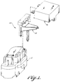
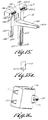
- mounting apparatus 10 for electrical motor control components made in accordance with the invention comprises a housing 12, a capacitor support 14 and a capacitor 16 shown in Fig. 1.
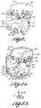
- Fig. 2 which shows a housing 12 with its cover removed before placing any internal parts therein
- Fig. 2a similar to Fig. 2 but shown with several internal components inserted which will be described below, the housing is formed with a bottom wall 20 and upstanding sidewalls 22.
- the housing is formed with a first cavity portion 24 in which a motor starting positive temperature coefficient (PTC) of resistivity switch is disposed and is therefore formed of suitable electrically insulative material such as Ryton R4 a trademark of Phillips Petroleum Company for polyphenylene-sulfide resin or Durez 25378 a trademark of Durez Company for phenolic which is capable of being subjected to relatively high temperature conditions.
- PTC switch comprises a bottom electrically conductive plate 26 of suitable material such as phosphor bronze which lies on bottom wall 20 as seen in Figs. 2a, 4a and 4b.
- An electrically conductive resilient contact member 28 which may be formed of suitable material such as stainless steel is electrically and mechanically attached to plate 26 in any suitable manner as by welding.
- Contact member 28 is generally U-shaped with its bight portion attached to plate member 26 and the distal free ends of its arms adapted to engage a conventional PTC element such as a generally cylindrical element or disc 30 (see Figs. 3a, 3b, 3c) of doped barium titanate having conductive coatings provided on opposite faces thereof (not shown).
- Plate 26 preferably is provided with orientation slots 32, 34, 36 to interact with respective ribs 38, 40, 42 projecting upwardly from bottom wall 20 to locate the plate 26 in a selected position.
- Plate 26 is also formed with an integrally attached double ended female pin connector 44 which is disposed in alignment with a first pin receiving aperture 46 formed in bottom wall 20 and with an integrally attached arm 48 having an end portion 52 extending laterally to a first intermediate terminal seat 54.
- End portion 52 is formed with an aperture 56 having a plurality of tabs 58 extending into the aperture. End portion 52 is received on terminal seat 54 with apertures 56 aligned with a recessed portion 60 of the terminal seat (Fig. 7).
- pin connector 44 has a cutout 44.1. Plate 26 is inserted into cavity portion 24 with cutout 44.1 receiving projection 44.2 (Fig. 2b) therethrough to securely retain the connector in place. A similar cutout is provided on connector 68 to be discussed below to cooperate with a corresponding projection at its seat.
- Connector 44 is provided with a terminal blade 44.3 for connecting to a quick connect lead received through an aperture in the cover for certain wiring options to be discussed below.
- Plate 26 may also be formed with a tab 62 which extends laterally toward sidewall 22 over an aperture 64 in bottom wall 20 (Fig. 8) so that electrical connection can be made thereto by a contact member extending through aperture 64 if desired.
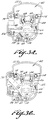
- Figs. 3a, 3b and 3c show several different electrical connection alternatives which can be provided for different types of split phase motors.
- PTC element 30 is received on resilient contact 28 and a top conductive contact plate with another resilient contact member 28 connected thereto is disposed on top of the PTC element 30.
- housing 12 is configured such that it can readily be received within the existing fences and covers provided on the majority of compressors. Mounting plates 26 and 28 horizontally on bottom wall 20 of the housing results in being able to accept a range of PTC element sizes and still stay within the confines dictated by such fences.
- the housing made in accordance with the invention can accommodate PTC element sizes anywhere from 12mm to 21mm in diameter.
- placing the bottom plate horizontally on bottom wall 20 results in improved thermal cycling characteristics by reducing the cool down time of the PTC element decreasing the power consumption or without materially affecting the switching point of the PTC element.
- This improved result is related, at least in part, to the heat sinking effect of the plate and bottom wall which is not obtained in the conventional vertically mounted PTC element starting switches.
- a female pin connector 68 is integrally attached to plate 66 and is aligned with a second pin receiving aperture 70 formed in bottom wall 20.
- Arm 48 attached to bottom conductive plate 26 can be removed or, if desired it can be used to provide electrical connection to a lead inserted through bore 56 through an aperture in the cover to be discussed below.
- connections for an inductive start, capacitor run or resistance start capacitor run motor in which a second integrally attached electrically conductive arm 72 is provided which extends laterally from plate 66' to a second intermediate terminal seat 74.
- a second integrally attached electrically conductive arm 72 is provided which extends laterally from plate 66' to a second intermediate terminal seat 74.
- end 76 of arm 72 is provided with an aperture 78 in which a plurality of tabs 80 extend, the apertures being in alignment with a recess 82 (Fig. 7).
- Fig. 3c shows a variation used in conjunction with a capacitor start, capacitor run motor in which top conductive plate 66'' has an integrally attached female connector 71 disposed over a peg 73 adjacent an aperture 75 in bottom wall 20 through which a contact probe can be inserted to engage connector 71 or connection can be made through an aperture in the cover in alignment with peg 73 as will become clear when the cover is discussed in detail below.
- Jumper 77 has a blade connector portion 77.1 aligned with a pin receiving aperture 70 and extends to end 77.2 in which an aperture 77.3 having tabs 77.4 extending therein (see Figs. 6a, 6b) is received on intermediate terminal seat 74.
- bullet lead-in 77.5 may be provided depending on the material used and its thickness.
- Motor protector 84 comprises an electrically insulative base portion 86 mounting a snap acting disc 88 formed of thermostat metal which is movable between opposite dished configurations in response to temperature.
- a movable contact arm 90 cantilever mounted at 92 has a movable electrical contact 94 mounted on a free end thereof adapted to move into and out of electrical engagement with stationary contact 96 in response to the dished configuration of disc 88.
- An electrical resistance heater means 98 is electrically coupled to the motor circuit current to heat the thermostat disc.
- Resilient female pin connector means 100 is adapted to be received on a header pin while terminal means 102 is adapted for connection to a power source.
- motor protector 84 in effect floats within loop portion 22.2 with its female pin connector 100, along with female pin connector 44 and 68, receivable on the header pins of a compressor. A detailed description of motor protector 84 is set forth in U.S. Patent No. 4,241,370 which is incorporated herein by this reference.
- Pin connectors 44, 68 and 77.1 are formed with the female connector portion having vertical walls defining a pin receiving opening configured, relative to a plane passing vertically through the walls, generally as a triangle having a base and an open vertex formed by the legs extending from the base which are spaced relative to one another so that a pin received in the opening forces the legs apart to provide a secure electrical connection as well as a self-centering mechanism for the respective plate or jumper arm to reduce stresses which could otherwise occur.
- connector 68 has a base portion 68.1 with legs 68.2 and 68.3 extending therefrom toward each other but having end portions spaced apart to form an open vertex.
- a pin inserted between walls 68.2 and 68.3 with force the legs apart slightly and will center plate 66' automatically aligning connector 68 with the pin.
- motor protector 84 is free to float within loop 22.2 so that misalignment relative to a pin to be inserted into connector 100 does not cause a problem, normally if a misaligned pin is forced into a conventional female connector such as connector 100 the connector can be spread apart resulting in ineffective electrical engagement with the pin.
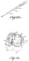
- Figs. 13 and 14 show a cover 106 adapted to be received on upstanding wall 22 including loop portion 22.2.
- Cover 106 has a top wall 108 with depending sidewalls 110.
- Cover 106 is formed of a suitable electrically insulative material such as Noryl N225, a trademark of General Electric for polyphenylene oxide (PPNOX), PPO-phenylene oxide, or Celanex for polybutylene terephthalate, which has lower high temperature capability and therefore is less expensive than housing 12 which mounts PTC element 30 and also provides excellent impact resistance.
- PPNOX polyphenylene oxide
- PPO-phenylene oxide PPO-phenylene oxide
- Celanex for polybutylene terephthalate
- Cover 106 is formed with downwardly depending pins 112 having a projecting portion 112.1 which are adapted to be received in bores 114 of housing 12 with portion 112.1 captured beyond the thickness of the portion of the housing through which bores 114 extend.
- a downwardly extending tab 116 having an outwardly extending lip is adapted to be received under a shelf 118 of enabling the housing and cover to snap together.
- a raised platform 124 having a groove area 126 extends above top surface 108 to serve as a strap guide. That is, after placing the housing on compressor header pins a strap can be placed over the housing to secure it to the compressor housing.
- the length of sidewalls 110 of cover 106 preferably are selected to form a cavity 126 to accommodate optional components, such as a coil for applications such as those shown in copending application Serial No. 442,802 assigned to the assignee of the present invention.
- a relay coil is placed in series with the main winding and contacts are provided to deenergize a PTC starter at a predetermined main winding current.
- Top wall 108 of cover 106 is formed with first and second apertures 128, 130 therethrough aligned respectively with first and second pin receiving apertures 46, 70 and have sidewalls 132 contiguous to the apertures 128, 130 extending slightly beyond sidewall 110 to serve as a guide in cases where it is desirable to make electrical connection with female connectors 44, 68 from above the housing. For example, such connection would facilitate connection to a remote capacitor.
- a quick connect lead such as 44.4 shown in Figs. 13a and 13b is received in aperture 128 shown in Fig. 11 with the distal free end 44.5 of tongue 44.6 of the quick connect riding in rectangular cutout portion 128.1 shown in Figs. 11 and 13 until projection 44.7 in tongue 44.6 is received in aperture 45 of the blade portion of terminal 44 (Fig.
- All of the connector blades are provided with locking apertures similar to 44.3, including the terminal blade of the motor protector, to provide a positive locking function with tool 14.8 required for removal of the respective lead.
- Cutout portions 130.1 and 133.1 are provided for apertures 130, 133 respectively for that purpose.
- a third aperture 133 is formed in cover 106 in alignment with optional terminal area 71 shown in Fig. 3c discussed supra.
- a power lead guide 134 is aligned with and is in communication with the interior of tubular portion 82 to accommodate reception of a power supply quick connector to be connected to the protector 84.
- guide 134 comprises a tubular wall portion and is provided with a diamond shaped unidirectional wedge 134.1 having a knife edge 134.2 facing outwardly, or upwardly as seen in Fig. 12, and a knife edge 134.3 facing inwardly in the tubular wall portion.
- the wedge has a flat base portion 134.4 facing downwardly as seen in Fig. 12.
- wedge 134.1 will guide the lead so that it will properly seat and lock onto terminal blade 102 and when the housing is removed from the pins the wedge jams against the quick connect resulting in locking the motor protector to the housing so that both the housing and the protector will be removed simultaneously with no live parts exposed.
- an arcuately extending rib 104 depends downwardly from bottom wall 20 and is adapted to fit closely adjacent to the collar or sleeve portion of the compressor header so that lateral forces exerted on housing 12 will be transferred to the compressor housing.
- a capacitor mounting platform 136 is integrally attached to cover 106 and is formed with first and second bracket leg apertures 138, 140 one side of which being contiguous with sidewall portion 110.2 Guide grooves 142 extending along the height of cover 108 are formed in wall portion 110.2 in alignment with each aperture 138, 140.
- a capacitor support bracket 14 composed of suitable electrically insulative material such as Noryl N225 or Celanex 4300 a trademark of Celanese Corporation for polybutylene terephthalate, has first and second parallel legs 150, 152 extending from a terminal block 154. Legs 150, 152 each has embedded therein a respective electrical conductor 156, 158 preferably formed of steel cored copper.
- Conductors 156, 158 have first and second ends, the first end of which extends into a respective recess 160, 162 and is bent into a loop having parallel segments 156.1, 156.2, 158.1, 158.2, with segments 156.1 and 158.1 having a centrally disposed portion 156.3, 158.3 respectively, projecting toward segment 156.2, 158.2 respectively to accommodate capacitor terminal blades which may be askew in good electrical engagement upon insertion into the conductive loops.
- the second end of each conductor 156, 158 extends beyond the distal free end of respective support bracket legs 150.1, 152.1.
- a capacitor support means in the form of an elongated arm 164 extends generally 90° from legs 150, 152 and is provided with a generally cylindrical outer distal end 166.
- a small protrusion 150.2 is formed on the rear lower portion of leg 150, a similar one is also formed on leg 152 but is not shown, which is adapted to ride in grooves 142 of cover 108 and bottom out at the end of grooves 142 as will be explained below.
- a capacitor 16 shown in Fig. 16 having blade terminals C1, C2 at one end is provided with a locking tab 170 extending from an opposite end.
- Tab 170 has an opening 172 which is adapted to clampingly receive distal end 166 of arm 164.
- capacitor 16 is placed on support 14 with terminal C2 received between loop segments 158.1, 158.2 in electrical engagement with projection 158.3, terminal C1 between loop segments 156.1, 156.2 in electrical engagement with projection 156.3 and distal end 166 received in opening 172 of tab 170.
- cover 108 disposed on housing 12 and conductive arms 48, 72 shown in Fig. 3b, legs 150, 152 are inserted through apertures 138, 140 respectively, the protrusions on the rear of the legs riding in grooves 142 until they bottom out against the end of the groove (Fig. 11).
- legs 150, 152 are inserted into the cavity 24 of housing 12 the second ends of conductors 156, 158 approach distal end portions 76, 52 respectively and eventually are inserted through respective apertures 78, 56 with tabs 80, 58 making electrical engagement with the respective conductors and being locked thereto.
- capacitor mounting and electrical connector bracket made in accordance with the invention offers is that by slightly modifying the bracket various capacitors can be accommodated regarding specific sizes, as well as varying the specific location of the capacitor in response to temperature limitations of the capacitor chosen without any changes required in the housing or in wiring provisions while meeting appropriate safety code requirements.
- housing 12 and cover 106 can be used without support bracket 14 and capacitor 16 in applications where a capacitor is not desired.
- a lead can be inserted through aperture 140 into electrical contact with arm 48 as discussed supra with respect to Fig. 3a.
- a capacitor it can easily be added to the housing and cover without having to provide additional wiring connections and the like.
- the starting switch can be used with virtually any split phase motor.
- An additional advantage provided by the invention is the elimination of the cover normally required for electrical enclosure required by safety organizations since the function is provided by the mounting apparatus of the invention.
Landscapes
- Engineering & Computer Science (AREA)
- Power Engineering (AREA)
- Motor Or Generator Frames (AREA)
- Induction Machinery (AREA)
Applications Claiming Priority (2)
| Application Number | Priority Date | Filing Date | Title |
|---|---|---|---|
| US07/708,535 US5170307A (en) | 1991-05-31 | 1991-05-31 | Mounting apparatus for electrical motor control components |
| US708535 | 1991-05-31 |
Publications (3)
| Publication Number | Publication Date |
|---|---|
| EP0516442A2 true EP0516442A2 (de) | 1992-12-02 |
| EP0516442A3 EP0516442A3 (en) | 1993-06-30 |
| EP0516442B1 EP0516442B1 (de) | 1996-12-18 |
Family
ID=24846174
Family Applications (1)
| Application Number | Title | Priority Date | Filing Date |
|---|---|---|---|
| EP92304885A Expired - Lifetime EP0516442B1 (de) | 1991-05-31 | 1992-05-29 | Haltevorrichtung für Regulierorgane für elektrischen Motor und Verfahren zum Ausrücken der Verbinder |
Country Status (5)
| Country | Link |
|---|---|
| US (1) | US5170307A (de) |
| EP (1) | EP0516442B1 (de) |
| JP (1) | JP3231843B2 (de) |
| KR (1) | KR100270950B1 (de) |
| DE (1) | DE69215962T2 (de) |
Cited By (4)
| Publication number | Priority date | Publication date | Assignee | Title |
|---|---|---|---|---|
| WO1998021735A1 (en) * | 1996-11-13 | 1998-05-22 | Texas Instrumentos Eletrônicos Do Brasil Ltda. | An assembly of electric motor-controlling components |
| EP0813286A3 (de) * | 1996-06-10 | 1999-03-31 | ATB Austria Antriebstechnik Aktiengesellschaft | Steckerteil für einen Elektromotor |
| EP1657733A1 (de) * | 2004-11-16 | 2006-05-17 | Texas Instruments Korea Limited | Verbindungsanordnung für einen Kühlschrankkompressor |
| CN116131502A (zh) * | 2023-04-19 | 2023-05-16 | 大唐(云南)水电联合开发有限责任公司 | 一种稳定型水轮机定子机座 |
Families Citing this family (19)
| Publication number | Priority date | Publication date | Assignee | Title |
|---|---|---|---|---|
| JP2527098B2 (ja) * | 1990-11-02 | 1996-08-21 | 日本鋼管株式会社 | 小型直流モ―タ |
| JPH08203704A (ja) * | 1995-01-27 | 1996-08-09 | Tdk Corp | 正特性サーミスタ装置 |
| US5576926A (en) * | 1995-04-03 | 1996-11-19 | American Technical Ceramics Corporation | Capacitor with buried isolated electrode |
| US5729416A (en) * | 1995-05-30 | 1998-03-17 | General Electric Company | Motor starter and protector module |
| US5684347A (en) * | 1995-06-07 | 1997-11-04 | General Electric Company | Mounting clip for a motor protector |
| JP2002008502A (ja) | 2000-06-23 | 2002-01-11 | Texas Instr Japan Ltd | 起動スイッチ及びこれを備えた電動機 |
| US6795283B2 (en) * | 2001-04-20 | 2004-09-21 | Texas Instruments Incorporated | Electricals package integrating run capacitor, motor protector and motor starter |
| KR100483557B1 (ko) * | 2002-08-09 | 2005-04-15 | 삼성광주전자 주식회사 | 밀폐형 압축기의 보호커버 장착장치 |
| US7099140B2 (en) * | 2002-11-07 | 2006-08-29 | General Electric Company | Method and apparatus for combining PTCR/OL and run capacitor |
| US20060042290A1 (en) * | 2004-09-01 | 2006-03-02 | Dai Xue Q | Split-type room air conditioner |
| ITPC20050006U1 (it) * | 2005-03-10 | 2006-09-11 | Electrica Srl | Rele' voltmetrico con base sagomata che presenta incavi atti a costituire sedi per l'inserimento di attacchi tipo "faston" |
| US7189111B2 (en) * | 2005-05-19 | 2007-03-13 | Bae Industries, Inc. | Stand-off bracket for securing a wire harness connector assembly to DC electric motor and associated method |
| US7622835B2 (en) * | 2007-01-26 | 2009-11-24 | Sensata Technologies Massachusetts, Inc. | Motor protector attachment system |
| US8587169B2 (en) | 2011-06-10 | 2013-11-19 | Nidec Motor Corporation | Motor endshield with capacitor retention structure |
| JP2013009585A (ja) * | 2011-06-23 | 2013-01-10 | Sensata Technologies Massachusetts Inc | 電動モータスタータ部品の組立 |
| KR101870897B1 (ko) * | 2011-10-17 | 2018-06-26 | 삼성전자주식회사 | 냉장고 및 냉장고용 압축기의 일체형 릴레이 모듈 |
| JP2013243190A (ja) * | 2012-05-18 | 2013-12-05 | Murata Mfg Co Ltd | サーミスタ装置 |
| BR102018010404B1 (pt) * | 2018-05-22 | 2023-10-17 | Whirlpool S.A. | Compressor de refrigeração compreendendo arranjo de proteção para conexões elétricas |
| KR102858183B1 (ko) | 2018-12-27 | 2025-09-10 | 엘지이노텍 주식회사 | 모터 |
Family Cites Families (6)
| Publication number | Priority date | Publication date | Assignee | Title |
|---|---|---|---|---|
| US4319299A (en) * | 1980-04-23 | 1982-03-09 | General Electric Company | Combination starter-protector device, apparatus utilizing such device, and methods of assembling |
| US4387412A (en) * | 1980-10-31 | 1983-06-07 | General Electric Company | Combination starter-protector device |
| IT8153530V0 (it) * | 1981-08-07 | 1981-08-07 | Aspera Spa | Gruppo di alimentazione e protezione di un compressore ermetico di una macchina frigorifera con regolazione termostatica |
| IT1147234B (it) * | 1981-09-03 | 1986-11-19 | Necchi Spa | Gruppo rele' d'avviamento, morsetteria per motocompressori ermetici |
| IT1181608B (it) * | 1985-03-15 | 1987-09-30 | Texas Instruments Italia Spa | Salvamotore sensibile alla corrente ed alla temperatura e motore che lo incorpora,in particolare per compressori di frigoriferi e simili |
| US4862306A (en) * | 1988-12-22 | 1989-08-29 | Texas Instruments Incorporated | Combination motor protector and starter apparatus |
-
1991
- 1991-05-31 US US07/708,535 patent/US5170307A/en not_active Expired - Lifetime
-
1992
- 1992-05-29 DE DE69215962T patent/DE69215962T2/de not_active Expired - Fee Related
- 1992-05-29 EP EP92304885A patent/EP0516442B1/de not_active Expired - Lifetime
- 1992-05-30 KR KR1019920009457A patent/KR100270950B1/ko not_active Expired - Fee Related
- 1992-06-01 JP JP18279492A patent/JP3231843B2/ja not_active Expired - Fee Related
Cited By (6)
| Publication number | Priority date | Publication date | Assignee | Title |
|---|---|---|---|---|
| EP0813286A3 (de) * | 1996-06-10 | 1999-03-31 | ATB Austria Antriebstechnik Aktiengesellschaft | Steckerteil für einen Elektromotor |
| WO1998021735A1 (en) * | 1996-11-13 | 1998-05-22 | Texas Instrumentos Eletrônicos Do Brasil Ltda. | An assembly of electric motor-controlling components |
| US6317304B1 (en) | 1996-11-13 | 2001-11-13 | Texas Instrumentos Electronicos Do Brasil Ltda. | Assembly of electric motor-controlling components |
| EP1657733A1 (de) * | 2004-11-16 | 2006-05-17 | Texas Instruments Korea Limited | Verbindungsanordnung für einen Kühlschrankkompressor |
| CN116131502A (zh) * | 2023-04-19 | 2023-05-16 | 大唐(云南)水电联合开发有限责任公司 | 一种稳定型水轮机定子机座 |
| CN116131502B (zh) * | 2023-04-19 | 2023-06-27 | 大唐(云南)水电联合开发有限责任公司 | 一种稳定型水轮机定子机座 |
Also Published As
| Publication number | Publication date |
|---|---|
| KR920022617A (ko) | 1992-12-19 |
| EP0516442A3 (en) | 1993-06-30 |
| JPH06165455A (ja) | 1994-06-10 |
| DE69215962T2 (de) | 1997-04-17 |
| EP0516442B1 (de) | 1996-12-18 |
| JP3231843B2 (ja) | 2001-11-26 |
| DE69215962D1 (de) | 1997-01-30 |
| US5170307A (en) | 1992-12-08 |
| KR100270950B1 (ko) | 2000-11-01 |
Similar Documents
| Publication | Publication Date | Title |
|---|---|---|
| EP0516442B1 (de) | Haltevorrichtung für Regulierorgane für elektrischen Motor und Verfahren zum Ausrücken der Verbinder | |
| EP0279023B1 (de) | Anschlussblock für Kompressor und Zusammenbau eines Überlastschutzes | |
| CA1131300A (en) | Combination starter-protector device | |
| US4462758A (en) | Water well pump control assembly | |
| US3921117A (en) | Solid state electrical switch | |
| US5616975A (en) | Integral connector and motor housing | |
| EP0688086A1 (de) | Bürstenloser Permanentmagnetmotor für Kühlaggregate | |
| EP0484077B1 (de) | Schutzvorrichtung für Kompressormotor | |
| US4131871A (en) | Electrical device and method | |
| US6331742B1 (en) | Electric motor connector module | |
| US4423399A (en) | Electromagnetic contactor | |
| US5021915A (en) | Combination starter-protector device and method of assembling same, overload protector and method of assembling same | |
| US6317304B1 (en) | Assembly of electric motor-controlling components | |
| JP2799204B2 (ja) | 電動機保護装置および始動器を組み合わせた装置 | |
| US4164000A (en) | Relay-starter electrical device for a prime mover | |
| US4327481A (en) | Method of assembling an electrical device | |
| US4267635A (en) | Method of making a solid state electrical switch | |
| US20020154459A1 (en) | Electricals package integrating run capacitor, motor protector and motor starter | |
| US4241494A (en) | Method of assembling an electrical device | |
| JP4444562B2 (ja) | 電動モータの始動システム用の構造装置 | |
| US4355458A (en) | Method of making an electrical control | |
| US4225210A (en) | Terminal and method of making | |
| KR100849513B1 (ko) | 전동기의 시동 시스템용 구조 장치 | |
| JPH09285066A (ja) | 電動式圧縮機の保護装置 |
Legal Events
| Date | Code | Title | Description |
|---|---|---|---|
| PUAI | Public reference made under article 153(3) epc to a published international application that has entered the european phase |
Free format text: ORIGINAL CODE: 0009012 |
|
| AK | Designated contracting states |
Kind code of ref document: A2 Designated state(s): DE FR GB IT NL |
|
| PUAL | Search report despatched |
Free format text: ORIGINAL CODE: 0009013 |
|
| AK | Designated contracting states |
Kind code of ref document: A3 Designated state(s): DE FR GB IT NL |
|
| 17P | Request for examination filed |
Effective date: 19931029 |
|
| 17Q | First examination report despatched |
Effective date: 19950721 |
|
| GRAG | Despatch of communication of intention to grant |
Free format text: ORIGINAL CODE: EPIDOS AGRA |
|
| GRAH | Despatch of communication of intention to grant a patent |
Free format text: ORIGINAL CODE: EPIDOS IGRA |
|
| GRAH | Despatch of communication of intention to grant a patent |
Free format text: ORIGINAL CODE: EPIDOS IGRA |
|
| GRAH | Despatch of communication of intention to grant a patent |
Free format text: ORIGINAL CODE: EPIDOS IGRA |
|
| GRAA | (expected) grant |
Free format text: ORIGINAL CODE: 0009210 |
|
| ITF | It: translation for a ep patent filed | ||
| AK | Designated contracting states |
Kind code of ref document: B1 Designated state(s): DE FR GB IT NL |
|
| PG25 | Lapsed in a contracting state [announced via postgrant information from national office to epo] |
Ref country code: NL Free format text: LAPSE BECAUSE OF FAILURE TO SUBMIT A TRANSLATION OF THE DESCRIPTION OR TO PAY THE FEE WITHIN THE PRESCRIBED TIME-LIMIT Effective date: 19961218 |
|
| REF | Corresponds to: |
Ref document number: 69215962 Country of ref document: DE Date of ref document: 19970130 |
|
| ET | Fr: translation filed | ||
| NLV1 | Nl: lapsed or annulled due to failure to fulfill the requirements of art. 29p and 29m of the patents act | ||
| PLBE | No opposition filed within time limit |
Free format text: ORIGINAL CODE: 0009261 |
|
| STAA | Information on the status of an ep patent application or granted ep patent |
Free format text: STATUS: NO OPPOSITION FILED WITHIN TIME LIMIT |
|
| 26N | No opposition filed | ||
| REG | Reference to a national code |
Ref country code: GB Ref legal event code: IF02 |
|
| PGFP | Annual fee paid to national office [announced via postgrant information from national office to epo] |
Ref country code: GB Payment date: 20030401 Year of fee payment: 12 |
|
| PGFP | Annual fee paid to national office [announced via postgrant information from national office to epo] |
Ref country code: FR Payment date: 20030505 Year of fee payment: 12 |
|
| PGFP | Annual fee paid to national office [announced via postgrant information from national office to epo] |
Ref country code: DE Payment date: 20030530 Year of fee payment: 12 |
|
| PG25 | Lapsed in a contracting state [announced via postgrant information from national office to epo] |
Ref country code: GB Free format text: LAPSE BECAUSE OF NON-PAYMENT OF DUE FEES Effective date: 20040529 |
|
| PG25 | Lapsed in a contracting state [announced via postgrant information from national office to epo] |
Ref country code: DE Free format text: LAPSE BECAUSE OF NON-PAYMENT OF DUE FEES Effective date: 20041201 |
|
| GBPC | Gb: european patent ceased through non-payment of renewal fee | ||
| PG25 | Lapsed in a contracting state [announced via postgrant information from national office to epo] |
Ref country code: FR Free format text: LAPSE BECAUSE OF NON-PAYMENT OF DUE FEES Effective date: 20050131 |
|
| REG | Reference to a national code |
Ref country code: FR Ref legal event code: ST |
|
| PG25 | Lapsed in a contracting state [announced via postgrant information from national office to epo] |
Ref country code: IT Free format text: LAPSE BECAUSE OF NON-PAYMENT OF DUE FEES;WARNING: LAPSES OF ITALIAN PATENTS WITH EFFECTIVE DATE BEFORE 2007 MAY HAVE OCCURRED AT ANY TIME BEFORE 2007. THE CORRECT EFFECTIVE DATE MAY BE DIFFERENT FROM THE ONE RECORDED. Effective date: 20050529 |