EP0516543A1 - Laufende, optoelektronische Bildaufnahmevorrichtung - Google Patents
Laufende, optoelektronische Bildaufnahmevorrichtung Download PDFInfo
- Publication number
- EP0516543A1 EP0516543A1 EP92401459A EP92401459A EP0516543A1 EP 0516543 A1 EP0516543 A1 EP 0516543A1 EP 92401459 A EP92401459 A EP 92401459A EP 92401459 A EP92401459 A EP 92401459A EP 0516543 A1 EP0516543 A1 EP 0516543A1
- Authority
- EP
- European Patent Office
- Prior art keywords
- memory area
- sensors
- travel
- image
- strip
- Prior art date
- Legal status (The legal status is an assumption and is not a legal conclusion. Google has not performed a legal analysis and makes no representation as to the accuracy of the status listed.)
- Granted
Links
Images


Classifications
-
- H—ELECTRICITY
- H04—ELECTRIC COMMUNICATION TECHNIQUE
- H04N—PICTORIAL COMMUNICATION, e.g. TELEVISION
- H04N25/00—Circuitry of solid-state image sensors [SSIS]; Control thereof
- H04N25/50—Control of the SSIS exposure
- H04N25/53—Control of the integration time
Definitions
- the invention relates to devices for taking pictures with scrolling and high spatial resolution. It finds a particularly important, although not exclusive, application in the field of observing terrestrial resources from a satellite placed in a low orbit with scrolling, using a device operating as a rake or "push-broom".
- the above type of picture-taking devices are used, the strip of which is made up of so-called charge-coupled or CCD sensors.
- the bar is often made up not of a single row or line of sensors, but of a matrix where the sensors are arranged in rows or rows and in columns, the number of which corresponds respectively to the level of desired summation and the number of elements of the scene.
- FIG. 1 shows schematically the operation of such a device, called integration and load transfer.
- the wide field optic 10 forms the image of a strip of terrain 12 on one of the lines 14 of sensors of a matrix network 16.
- the displacement of the satellite in the direction f0 causes the image of the field 12 to pass successively. from one line to the next, in the direction indicated by the arrow f1.
- Electronics associated with the device allows the charges accumulated by the sensors to be transferred from one line to the next at the rate corresponding to the sampling step d in the direction f0 of the travel, the step itself being linked to the distance between lines of the bar 16, and the magnification of the optics.
- the accumulated charges are finally transferred from the last line of the bar into a shift register and the latter is read in series during the time interval which separates two transfers.
- the analog output data are digitized in real time, in a converter then memorized or transmitted.
- the data rate at the output of the register is very high when a very high spatial resolution is sought.
- the bit rate of pixels at the output of the register is equal to: CV / d2 where C is the width of the transverse field, V is the speed of travel on the ground and d is the sampling step (assumed to be equal in the direction of travel and in the transverse direction).
- the bit rate of transmission to the ground is the product of the bit rate of pixels by the number of bits per pixel.
- the present invention aims to provide a shooting device of the type defined above, making it possible to significantly reduce the complexity of the systems placed downstream from the opto-electronic part and applicable to localized shooting.
- the invention proposes for this purpose a device according to claim 1.
- the read rate of the output shift register can be greatly reduced compared to the rate that is required in an uninterrupted coverage device.
- the invention also aims to increase the format of the images supplied by a scrolling camera of the type defined above, at least in the direction of travel of the satellite, at a given resolution.
- the invention uses an approach to the problem different from those previously known, based on the temporal separation of the image into two sub-images which may each have the format of a usual image, and this by using an image divider.
- the invention also proposes the alternating implementation of optical means for dividing the light flux received from the optics into two fractions corresponding to two successive half-views in the direction of travel and for directing each fraction towards one of two bars of sensors and comprising load transfer means each assigned to a bar and operating so alternated.
- the invention provides a device of the type defined above comprising optical, mechanical and / or electrical means for reconstructing a complete image from the alternating capture of two image fractions or sub-images in the scroll direction.
- the flux coming from the observed scene is shared, each fraction being directed towards one of the two arrays of sensors; the data transfer means each assigned to a strip operate alternately.
- the splicing operation can be carried out using a sharing of the flows by optical means working either in transmission or in reflection.
- the choice between the two variants will be made according to the particular conditions encountered. In particular it will be preferable to work in reflection when it is essential to avoid any weakening of light flux.
- the invention is of particular interest in the case of a device for taking pictures in non-contiguous fields of the kind mentioned above.
- the invention will be described in its application to taking terrestrial scrolling views, from a satellite in low orbit, using an integration and charge transfer detector, that is to say operating. as shown in FIG. 1. It would however be applicable to other types of shots, and in particular to shots in which the scrolling is obtained using a scanning mirror.
- N x P pixels which are not contiguous, separated from a minimum number of image formats, for example from at least nine image formats, as indicated on Figure 2.
- the invention makes it possible in this case to reduce in the 9/1 ratio the transmission rate required from the detector.
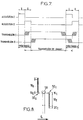
- the bottom line of Figure 3 shows the duration 9T available to transmit the pixels of an image acquired during duration T (upper line).
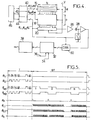
- the device can have the constitution shown in FIG. 4.
- the detector conventionally comprises a bar 16 constituting the image area, with M lines of N sensors.
- the detector also includes a memory area 18 to P lines of N sites, of the same constitution as the sensors, but "blind” that is to say away from light.
- the number of lines P is chosen according to the size of the image to be obtained, in the direction of scrolling.
- the detector comprises a reading zone, constituted by a shift register 20 whose output is connected to a reading channel.
- This channel comprises a preamplifier 26, sampling means 28 and an analog-digital converter 30 which quantifies the output voltages each coming from a photosensitive site, with a resolution sufficient to allow subsequent processing.
- the output words, each representing an image pixel are written into a random access memory 32 which can be commanded in writing by an input 34 and in reading by an input 36.
- the memory 32 can be followed by a processing circuit 38 or connected directly to an emission modulator. Since the memory area itself acts as a buffer, the memory 32 can be reduced to a few lines only, to allow the correct operation of the processing circuits.
- each zone 16, 18 and 20 has its own sequencer 40, 42 or 44.
- the clock provided by the sequencer 42 depends on the operating phase.
- the clock frequencies are controlled, as well as the distribution of the operating phases, by control electronics 46.
- the device is completed by bias circuits, providing the voltages necessary for the three zones, indicated by V.
- the retention of charges in the memory area 18 can reach several seconds in certain cases.
- the matrix can be cooled to a temperature of -20 ° C.
- the size of the elementary images is limited by that of the slices.
- the device shown in Figure 6 schematically allows, by sharing the light flux received from the optics into two fractions corresponding to two successive half-views in the direction of travel, to increase the size of the elementary images.
- the image divider 48 of which FIGS. 6A and 6B schematically show the two phases of alternating operation, works in transmission. It can be constituted by two glass prisms 50 and 52, each having a section in the shape of an isosceles right triangle, glued by their hypotenuse faces, one being covered with a semi-reflecting deposit 54. On each of the two exit faces of the divider 48 is fixed a detector 56 I or 56 II . The image areas 16 I and 16 II of the detectors are centered on the optical axis and optically conjugate so as to see the same scene at the same time. Detectors 56 I and 56 II are associated with sequencers of the type shown in FIG. 4, but operating with a time shift, as shown in FIG. 7.
- the image and memory zones of the detector 56 I detect and store the sub-image I.
- the detector 56 II is inactive or in the course of reading a sub- previous picture.
- the image and memory areas of the detector 56 II detect and store the sub-image II: during this period, the detector 56 I retains or transmits the data of the sub-image I.
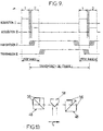
- FIG. 8 the elements corresponding to those of FIG. 6 are designated by the same reference numbers.
- a divider 58 with two orthogonal mirrors separates the field into two half-images which are received by the image zones 16 I and 16 II from two detectors 56 I and 56 II . Due to the spatial separation linked to the principle of division by mirrors, the sequencing is intended to eliminate any dead zone in the middle of the image. The operating schedule is then the one given in figure 9.
- the two detectors 56 I and 56 II are mounted head to tail.
Landscapes
- Engineering & Computer Science (AREA)
- Multimedia (AREA)
- Signal Processing (AREA)
- Transforming Light Signals Into Electric Signals (AREA)
- Image Analysis (AREA)
Applications Claiming Priority (2)
| Application Number | Priority Date | Filing Date | Title |
|---|---|---|---|
| FR9106525A FR2677207B1 (fr) | 1991-05-30 | 1991-05-30 | Dispositif de prise de vues opto-electronique a defilement. |
| FR9106525 | 1991-05-30 |
Publications (2)
| Publication Number | Publication Date |
|---|---|
| EP0516543A1 true EP0516543A1 (de) | 1992-12-02 |
| EP0516543B1 EP0516543B1 (de) | 1995-12-20 |
Family
ID=9413288
Family Applications (1)
| Application Number | Title | Priority Date | Filing Date |
|---|---|---|---|
| EP92401459A Expired - Lifetime EP0516543B1 (de) | 1991-05-30 | 1992-05-27 | Laufende, optoelektronische Bildaufnahmevorrichtung |
Country Status (3)
| Country | Link |
|---|---|
| EP (1) | EP0516543B1 (de) |
| DE (1) | DE69206885T2 (de) |
| FR (1) | FR2677207B1 (de) |
Cited By (1)
| Publication number | Priority date | Publication date | Assignee | Title |
|---|---|---|---|---|
| EP0907284A1 (de) * | 1997-10-03 | 1999-04-07 | Matra Marconi Space France | Lichtempfindliche ladungsgekoppelte Vorrichtung mit Ladungsakkumulation und Lidar mit einer solchen Vorrichtung |
Citations (3)
| Publication number | Priority date | Publication date | Assignee | Title |
|---|---|---|---|---|
| EP0030292A2 (de) * | 1979-12-10 | 1981-06-17 | International Business Machines Corporation | Ladungsübertragungsvorrichtung mit Laplacefunktion-Schnellwertbestimmung und zeitverzögernder und integrierender Bildmatrix |
| EP0257379A2 (de) * | 1986-08-19 | 1988-03-02 | KAPPA messtechnik GmbH | Verfahren zum Aufnehmen und Speichern von Bildern in schneller Folge |
| EP0369585A1 (de) * | 1988-09-26 | 1990-05-23 | Picker International, Inc. | Videokamera für die Überwachung |
Family Cites Families (1)
| Publication number | Priority date | Publication date | Assignee | Title |
|---|---|---|---|---|
| JPS5843671A (ja) * | 1981-09-10 | 1983-03-14 | Canon Inc | フレ−ム・トランスフア型撮像素子 |
-
1991
- 1991-05-30 FR FR9106525A patent/FR2677207B1/fr not_active Expired - Fee Related
-
1992
- 1992-05-27 DE DE69206885T patent/DE69206885T2/de not_active Expired - Fee Related
- 1992-05-27 EP EP92401459A patent/EP0516543B1/de not_active Expired - Lifetime
Patent Citations (3)
| Publication number | Priority date | Publication date | Assignee | Title |
|---|---|---|---|---|
| EP0030292A2 (de) * | 1979-12-10 | 1981-06-17 | International Business Machines Corporation | Ladungsübertragungsvorrichtung mit Laplacefunktion-Schnellwertbestimmung und zeitverzögernder und integrierender Bildmatrix |
| EP0257379A2 (de) * | 1986-08-19 | 1988-03-02 | KAPPA messtechnik GmbH | Verfahren zum Aufnehmen und Speichern von Bildern in schneller Folge |
| EP0369585A1 (de) * | 1988-09-26 | 1990-05-23 | Picker International, Inc. | Videokamera für die Überwachung |
Non-Patent Citations (2)
| Title |
|---|
| OPTICAL ENGINEERING, vol. 30, no. 4, avril 1991, pages 483-488, Bellingham US; GIORA EYTAN: "Airborne camera based on one dimensional linear array" * |
| PATENT ABSTRACTS OF JAPAN, vol. 7, no. 129 (E-179)[1274], 4 juin 1983; & JP-A-58 043 671 (CANON K.K.) 14-03-1983 * |
Cited By (3)
| Publication number | Priority date | Publication date | Assignee | Title |
|---|---|---|---|---|
| EP0907284A1 (de) * | 1997-10-03 | 1999-04-07 | Matra Marconi Space France | Lichtempfindliche ladungsgekoppelte Vorrichtung mit Ladungsakkumulation und Lidar mit einer solchen Vorrichtung |
| FR2769450A1 (fr) * | 1997-10-03 | 1999-04-09 | Matra Marconi Space France | Dispositif photosensible a couplage et accumulation de charges et lidar incorporant un tel dispositif |
| US6084659A (en) * | 1997-10-03 | 2000-07-04 | Matra Marconi Space France | Photosensitive charge coupled accumulation device and lidar incorporating such a device |
Also Published As
| Publication number | Publication date |
|---|---|
| EP0516543B1 (de) | 1995-12-20 |
| FR2677207B1 (fr) | 2002-03-29 |
| DE69206885T2 (de) | 1996-08-14 |
| DE69206885D1 (de) | 1996-02-01 |
| FR2677207A1 (fr) | 1992-12-04 |
Similar Documents
| Publication | Publication Date | Title |
|---|---|---|
| EP0738074B1 (de) | Detektionsverfahren mit verteilten Integrations- und Ausleseperioden für eine Abtastungskamera, und entsprechende Detektoranordnung | |
| EP2567537B1 (de) | Polychromatisches bildgebungsverfahren | |
| EP0254634B1 (de) | Verfahren und Vorrichtung zum optischen Abstandsmessen | |
| FR2696843A1 (fr) | Appareil de prise de vues à distance, à haute résolution, pour porteur aérien. | |
| FR2736492A1 (fr) | Procede et systeme pour compenser le deplacement pendant la formation d'image | |
| FR2692423A1 (fr) | Caméra d'observation multistandard et système de surveillance utilisant une telle caméra. | |
| EP1433012B1 (de) | Passive optoelektronische überwachungseinrichtung | |
| FR2503391A1 (fr) | Systeme de balayage optique | |
| EP0920677B1 (de) | Verfahren und vorrichtung zur lufterde erkennung für eine elektronische anlage | |
| EP2538665B1 (de) | Bildaufnehmer mit selektiver Bilderfassung und Verfahren zur Erkennung von Blitzen. | |
| EP3777129B1 (de) | Luftbildsensor zur aufnahme von matrixbildern durch zeitliche verschiebung und multispektrale summation | |
| EP0341142A2 (de) | Beobachtungsvorrichtung durch Abtastung eines Raumkörpers und Messung der Winkelgeschwindigkeit eines Raumfahrzeuges, Beobachtungssystem für seine Anwendung und Raumfahrzeug mit diesem System | |
| EP0516543B1 (de) | Laufende, optoelektronische Bildaufnahmevorrichtung | |
| EP0236157A1 (de) | Schnelle Abtastvorrichtung für einen optischen in einer Matrixform angeordneten Ladungsübertragungssensor bei einer Halbbildübertragung für die Detektion von kurzen Videobildern | |
| EP0604302B1 (de) | Verfahren und Vorrichtung zur Analyse von sich bewegenden Objekten mittels Radiographie | |
| FR2755337A1 (fr) | Systeme de camera | |
| EP3671280B1 (de) | Hochpräzises datierungssystem der passage eines objekts, insbesondere eines satelliten | |
| EP3217649B1 (de) | Bilderfassungssensor mit erweiterter zeitverzögerung und integration | |
| EP3839814B1 (de) | Bordseitiges optisches beobachtungsinstrument mit variabler räumlicher und spektraler auflösung | |
| EP4186227B1 (de) | Flugzeitsensor für abstandsmessung mit pixel mit mehreren speicherknoten | |
| EP0445038A1 (de) | Bildabtastungsvorrichtung, bestehend aus einer Matrix statischer Ladungssensoren | |
| FR2588709A1 (fr) | Systeme de grossissement d'une partie d'une image dans les dispositifs de prise de vues video notamment a senseur a transfert de charges | |
| EP4405648A1 (de) | Verfahren zur erfassung multispektraler bilder und panchromatischer miniaturbilder | |
| FR2661510A1 (fr) | Procede et dispositif d'imagerie optique a trois dimensions. | |
| FR2735935A1 (fr) | Dispositif a couplage de charges adapte a l'acquisition rapide d'un signal lumineux et son application dans un lidar |
Legal Events
| Date | Code | Title | Description |
|---|---|---|---|
| PUAI | Public reference made under article 153(3) epc to a published international application that has entered the european phase |
Free format text: ORIGINAL CODE: 0009012 |
|
| AK | Designated contracting states |
Kind code of ref document: A1 Designated state(s): BE DE GB IT NL |
|
| 17P | Request for examination filed |
Effective date: 19921207 |
|
| 17Q | First examination report despatched |
Effective date: 19950320 |
|
| GRAA | (expected) grant |
Free format text: ORIGINAL CODE: 0009210 |
|
| AK | Designated contracting states |
Kind code of ref document: B1 Designated state(s): BE DE GB IT NL |
|
| REF | Corresponds to: |
Ref document number: 69206885 Country of ref document: DE Date of ref document: 19960201 |
|
| ITF | It: translation for a ep patent filed | ||
| GBT | Gb: translation of ep patent filed (gb section 77(6)(a)/1977) |
Effective date: 19960326 |
|
| PLBE | No opposition filed within time limit |
Free format text: ORIGINAL CODE: 0009261 |
|
| STAA | Information on the status of an ep patent application or granted ep patent |
Free format text: STATUS: NO OPPOSITION FILED WITHIN TIME LIMIT |
|
| 26N | No opposition filed | ||
| PGFP | Annual fee paid to national office [announced via postgrant information from national office to epo] |
Ref country code: GB Payment date: 19980519 Year of fee payment: 7 |
|
| PGFP | Annual fee paid to national office [announced via postgrant information from national office to epo] |
Ref country code: BE Payment date: 19980615 Year of fee payment: 7 |
|
| PG25 | Lapsed in a contracting state [announced via postgrant information from national office to epo] |
Ref country code: GB Free format text: LAPSE BECAUSE OF NON-PAYMENT OF DUE FEES Effective date: 19990527 |
|
| PG25 | Lapsed in a contracting state [announced via postgrant information from national office to epo] |
Ref country code: BE Free format text: LAPSE BECAUSE OF NON-PAYMENT OF DUE FEES Effective date: 19990531 |
|
| BERE | Be: lapsed |
Owner name: MATRA MARCONI SPACE FRANCE Effective date: 19990531 |
|
| GBPC | Gb: european patent ceased through non-payment of renewal fee |
Effective date: 19990527 |
|
| PGFP | Annual fee paid to national office [announced via postgrant information from national office to epo] |
Ref country code: NL Payment date: 20040429 Year of fee payment: 13 |
|
| PGFP | Annual fee paid to national office [announced via postgrant information from national office to epo] |
Ref country code: DE Payment date: 20040506 Year of fee payment: 13 |
|
| PG25 | Lapsed in a contracting state [announced via postgrant information from national office to epo] |
Ref country code: IT Free format text: LAPSE BECAUSE OF NON-PAYMENT OF DUE FEES;WARNING: LAPSES OF ITALIAN PATENTS WITH EFFECTIVE DATE BEFORE 2007 MAY HAVE OCCURRED AT ANY TIME BEFORE 2007. THE CORRECT EFFECTIVE DATE MAY BE DIFFERENT FROM THE ONE RECORDED. Effective date: 20050527 |
|
| PG25 | Lapsed in a contracting state [announced via postgrant information from national office to epo] |
Ref country code: NL Free format text: LAPSE BECAUSE OF NON-PAYMENT OF DUE FEES Effective date: 20051201 Ref country code: DE Free format text: LAPSE BECAUSE OF NON-PAYMENT OF DUE FEES Effective date: 20051201 |
|
| NLV4 | Nl: lapsed or anulled due to non-payment of the annual fee |
Effective date: 20051201 |