EP0516919B1 - Appareil laser à circulation de gaz et sa méthode d'opération - Google Patents
Appareil laser à circulation de gaz et sa méthode d'opération Download PDFInfo
- Publication number
- EP0516919B1 EP0516919B1 EP92101788A EP92101788A EP0516919B1 EP 0516919 B1 EP0516919 B1 EP 0516919B1 EP 92101788 A EP92101788 A EP 92101788A EP 92101788 A EP92101788 A EP 92101788A EP 0516919 B1 EP0516919 B1 EP 0516919B1
- Authority
- EP
- European Patent Office
- Prior art keywords
- gas
- trap
- laser
- liquid nitrogen
- solidified
- Prior art date
- Legal status (The legal status is an assumption and is not a legal conclusion. Google has not performed a legal analysis and makes no representation as to the accuracy of the status listed.)
- Expired - Lifetime
Links
Images



Classifications
-
- H—ELECTRICITY
- H01—ELECTRIC ELEMENTS
- H01S—DEVICES USING THE PROCESS OF LIGHT AMPLIFICATION BY STIMULATED EMISSION OF RADIATION [LASER] TO AMPLIFY OR GENERATE LIGHT; DEVICES USING STIMULATED EMISSION OF ELECTROMAGNETIC RADIATION IN WAVE RANGES OTHER THAN OPTICAL
- H01S3/00—Lasers, i.e. devices using stimulated emission of electromagnetic radiation in the infrared, visible or ultraviolet wave range
- H01S3/02—Constructional details
- H01S3/03—Constructional details of gas laser discharge tubes
- H01S3/036—Means for obtaining or maintaining the desired gas pressure within the tube, e.g. by gettering, replenishing; Means for circulating the gas, e.g. for equalising the pressure within the tube
-
- H—ELECTRICITY
- H01—ELECTRIC ELEMENTS
- H01S—DEVICES USING THE PROCESS OF LIGHT AMPLIFICATION BY STIMULATED EMISSION OF RADIATION [LASER] TO AMPLIFY OR GENERATE LIGHT; DEVICES USING STIMULATED EMISSION OF ELECTROMAGNETIC RADIATION IN WAVE RANGES OTHER THAN OPTICAL
- H01S3/00—Lasers, i.e. devices using stimulated emission of electromagnetic radiation in the infrared, visible or ultraviolet wave range
- H01S3/14—Lasers, i.e. devices using stimulated emission of electromagnetic radiation in the infrared, visible or ultraviolet wave range characterised by the material used as the active medium
- H01S3/22—Gases
- H01S3/223—Gases the active gas being polyatomic, i.e. containing two or more atoms
- H01S3/225—Gases the active gas being polyatomic, i.e. containing two or more atoms comprising an excimer or exciplex
Definitions
- the present invention relates to a gas laser and particularly relates to a gas laser using a laser gas medium while circulating and purifying the laser gas medium.
- solidification means a state in which gas molecules lose kinetic energy thereof on a surface to become solid on the surface.
- adsorption means a state in which gas molecules attached to a surface have kinetic energy corresponding to the temperature of the surface so that the gas molecules are being attached under the balance between desorbing force and attaching force. Accordingly, solidified gas molecules are not replaced by others but adsorbed gas molecules are replaced by gas molecules having stronger adsorbing force.
- the invention is not limited to such KrF excimer laser.
- the invention may be applied to ArF excimer laser and the like.
- KrF excimer laser is operated in a manner so that a mixture gas of about 95-99% of Ne, about 1-5% of Kr and about 0 ⁇ .1-0 ⁇ .5% of F 2 is contained as a laser gas medium in a laser tube, which is made of metal, glass, plastics, ceramics or the like, and has mirrors disposed at the opposite ends of the laser tube, and light emission is caused in the laser gas medium through electric discharge to thereby cause resonance.
- a fluorine gas is strong in reactivity and, in particular, fluorine gas excited by electric discharge or other excitation means is so strong in reactivity that reaction between the fluorine gas and constituent materials of the laser vessel is caused by the electric discharge.
- This can generate a level of impurities in the laser gas which causes the laser output from the KrF excimer laser to decrease as the number of discharge pulses increases due to the presence of these impurities.
- the present invention relates to a method for operating a gas laser apparatus and to a gas laser apparatus as referred to in independent claims 1 and 4, respectively.
- An object of the present invention is to provide a gas laser apparatus operating method in which it is easy to keep the laser output power constant for a long time.
- Another object of the present invention is to provide a gas laser apparatus in which it is easy to keep the laser output power constant for a long time.
- a method for operating a gas laser apparatus comprising the steps of: preliminarily attaching a solidifiable gas which is solidified at the trap temperature in a low temperature trap containing a filler so as to solidify the solidifiable gas; and then bringing the solidified solidifiable gas into contact with the laser gas medium.
- a gas laser apparatus comprising: a laser tube containing a laser gas medium and for emitting laser light; a low temperature trap containing a filler being connected to the laser tube so as to form a circulation path; a refrigerant vessel for refrigerating the low temperature trap to a predetermined temperature; and means for supplying to the low temperature trap, a solidifiable gas which solidifies at the predetermined temperature.
- the surface of the refrigerated wall can be caused to serve as an adsorption surface by preliminarily solidifying a gas which is solidified at a refrigeration temperature in a low temperature trap filled with a filler.
- FIGs. 1A and 1B show an embodiment of the present invention, in which Fig. 1A and 1B are schematic sectional views of a laser gas medium purifying system for explaining a laser gas medium purifying method according to an embodiment of the present invention.
- Figs. 2 is graphs for explaining a conventional technique.
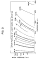
- Fig. 3 is a graph showing vapor pressure curves of laser gases and impurities.
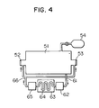
- Fig. 4 is a schematic sectional view showing a KrF excimer laser apparatus having a conventional liquid nitrogen refrigerated trap.
- Fig. 5A and 5B are graphs showing experimental results which form the foundation of the present invention, in which Fig. 5A is a graph showing a result in which Xe mixed in He is trapped on the liquid nitrogen trap, and Fig. 5B is a graph showing a result in which air components mixed in He are adsorbed on the liquid nitrogen refrigerated adsorption tower.
- a laser tube 51 has, at its one and the other ends respectively, a mirror 52 and a half mirror 53 having a desired reflectivity and a desired transmittance.
- Raw material gases are supplied from a gas source 54.
- the changes of the characteristics of the laser with the passage of time in the case where laser oscillation is continued under the condition that the inside of the laser tube 51 is first exhausted through an exhaust valve 55 and then fresh raw material gases are supplied from the gas source 54 to a predetermined pressure while the valve 55 being closed will be described hereinbelow.
- Part (A) of Fig. 2 shows laser output power
- parts (B) and (C) of Fig. 2 show gas component concentrations in the laser tube 51. In each graph, the abscissa represents the time.
- laser output power is about zero before oscillation is caused.
- the laser output power reaches a large value rapidly.
- the laser output power gradually decreases with the passage of oscillation time due to depletion of fluorine and increase of impurity concentrations.
- the gas components in the laser tube 51 are kept almost constant and impurities such as N 2 , O 2 , HF and SiF 4 exist slightly. Though not shown, the concentrations of Ne and Kr, which are main components of the laser gas medium, are kept almost constant.
- the concentrations of impurities such as CF 4 , HF, SiF 4 , etc. gradually increase as shown in part (C) of Fig. 2.
- the concentration of F 2 as a constituent component of the laser gas medium gradually decreases. It is considered that the lowering of the laser output power is caused by both the increase of these impurities and the decrease of F 2 which is a necessary constituent component of the laser gas medium.
- the laser gas medium in the KrF excimer laser contains Ne, Kr and F 2 as necessary components and contains CF 4 , SiF 4 , HF, etc. as main impurity gases.
- Fig. 4 schematically shows a KrF excimer laser apparatus having a liquid nitrogen refrigerated trap.
- a laser gas medium from the gas source 54 is supplied to the laser tube 51 having the reflection mirror 52 and the half mirror 53.
- the laser tube 51 is provided further with a gas outlet path 61 and a gas feedback pact 66.
- a dust filter 62, a liquid nitrogen refrigerated trap 64 and a pump 65 are connected between the gas outlet path 61 and the gas feedback path 66.
- the liquid nitrogen refrigerated trap 64 is immersed in a liquid nitrogen tank 63 and refrigerated to the temperature of liquid nitrogen.
- the laser gas medium within the laser tube 51 is fed into the liquid nitrogen refrigerated trap 64 from the gas outlet path 61 through the dust filter 62, and is fed back into the laser tube 51 from the pump 65 through the gas feedback path 66 after those components which exhibit low vapor pressures at the temperature of liquid nitrogen are trapped on the wall surface of the liquid nitrogen refrigerated trap 64.
- the impurity gases CF 4 , SiF 4 and HF respectively exhibit very low vapor pressures at the temperature of liquid nitrogen, so that impurity gas molecules colliding with the wall surface of the liquid nitrogen refrigerated trap 64 are trapped thereon.
- Kr as a constituent member of the laser gas medium exhibits a low vapor pressure at the temperature of liquid nitrogen, so that the probability that Kr is trapped to the liquid nitrogen refrigerated trap is high.
- the Kr content in the laser gas medium decreases when Kr is trapped to the liquid nitrogen refrigerated trap.
- the gas flow rate is generally about 5 Nl/min and the gauge gas pressure is generally in the range 2 to 5 Kg/cm 2 G (total pressure: 3-6 Kg/cm 2 ).
- FIG. 5A shows an result of an experiment in which Xe mixed in He is trapped. After the outlet and inlet of the liquid nitrogen refrigerated trap were filled with glass wool, the liquid nitrogen refrigerated trap was refrigerated by liquid nitrogen. The concentrated of Xe was measured after He mixed with a predetermined concentration of Xe is allowed to pass through the liquid nitrogen trap. The abscissa represents the concentration of Xe at the inlet of the trap in ppm. The ordinate represents the concentration of Xe at the outlet of the trap in ppm.
- the concentration of Xe at the outlet of the trap is plotted when the concentration of Xe in He gas, which is supplied to the liquid nitrogen refrigerated trap, is changed variously. While the concentration of Xe at the inlet of the trap is low, the concentration of Xe at the outlet of the trap exhibits a value almost equal to the concentration of Xe at the inlet of the trap. This shows the fact that Xe is little trapped to the liquid nitrogen refrigerated trap. When the concentration of Xe at the inlet of the trap approaches 1ppm, on the other hand, the concentration of Xe at the outlet of the trap becomes lower than the concentration of Xe at the inlet of the trap.
- impurity gases which become a problem in KrF excimer laser have concentrations not lower than the order of ppm as shown in parts (A) to (C) of Fig 2. It is obvious that impurity gases such as SiF 4 , HF, etc. being lower in vapor pressure than Xe at the temperature of liquid nitrogen are trapped to the liquid nitrogen refrigerated trap more perfectly than Xe.
- Fig. 5B shows a result of an adsorption experiment in which air mixed in He is adsorbed by using active carbon refrigerated to the temperature of liquid nitrogen.
- the active carbon was refrigerated to the temperature of liquid nitrogen.
- the respective concentrations of N 2 and O 2 , at the outlet of the adsorption tower were measured after air is mixed in He and is passed through the adsorption tower.
- the amount of added N 2 was about 40 ⁇ 0 ⁇ 0 ⁇ ppm and the amount of added O 2 was about 10 ⁇ 0 ⁇ 0 ⁇ ppm.
- the concentrations of N 2 and O 2 were both zero at the outlet of the adsorption tower.
- the solidified impurity gas components When impurity gas components, which are solidifiable at the temperature of the low temperature trap, are trapped to the refrigerated wall and solidified thereat, the solidified impurity gas components then serve as adsorbents in the same manner in a similar manner.
- main components of impurities to be removed are CF 4 , SiF 4 and HF.
- SiF 4 and HF lower in vapor pressure than Xe at the temperature of liquid nitrogen is solidified on the surface of the trap and, then, CF 4 higher in vapor pressure than Xe at the temperature of liquid nitrogen is adsorbed on the surface of the solidified Xe which serves as an adsorption surface. Accordingly, the KrF excimer laser gas medium can be efficiently purified using the liquid nitrogen refrigerated trap that contains the adsorbent which has been pretreated by solidifying X 2 at the trap temperature.
- Kr exhibiting a vapor pressure curve near that of CF 4 is also adsorbed on the surface of the liquid nitrogen refrigerated trap containing the solidified Xe, but the adsorption force of Kr is weaker than that of CF 4 because the vapor pressure of Kr is higher than that of CF 4 . Accordingly, though Kr may be adsorbed at the initial stage, CF 4 being stronger in adsorption force than Kr is substituted for Kr at the position where Kr is adsorbed, by the interaction between Kr and CF 4 to thereby expel Kr from the adsorbent when CF 4 is adsorbed. Accordingly, the consumption of Kr in the liquid nitrogen refrigerated trap becomes no problem.
- the concentration of impurities in the laser gas medium of the KrF excimer laser is merely limited by the starting time of the CF 4 concentration at the outlet of the liquid nitrogen refrigerated trap.
- adsorbed gases are Kr and CF 4 , so that other impurities are solidified on the surface of the liquid nitrogen trap without influence on other components of the laser gas medium.
- the solidified impurity gases serve as adsorbents similarly to Xe.
- the adsorbed Kr and CF 4 are desorbed so that a recycling treatment on the adsorption surface can be realized.
- Solidified impurities except Xe and CF 4 remain on the refrigerated wall and continuously serve as adsorbents.
- FIG. 1A and 1B An embodiment of the present invention is shown in the Figs. 1A and 1B. In the following, a method for purifying a laser gas medium of KrF excimer laser as shown in Fig. 4 and a system used therefor are described.
- a liquid nitrogen refrigerated trap 1 is filled with a filler 2 such as glass wool, metal packing, metal Dixon ring, etc.
- the filler may be formed of a metal, such as stainless steel, copper, aluminum, etc., having high heat conductivity at a predetermined refrigeration temperature.
- the filler is provided so that the trap is not blocked by solidification of gases and that the area touching passing gases becomes large.
- a gas inlet pipe 3 is connected to the upper portion of the liquid nitrogen refrigerated trap 1.
- a gas outlet pipe 4 is connected to the lower portion of the liquid nitrogen refrigerated trap 1.
- the liquid nitrogen refrigerated trap 1 thus filled with the filler 2 is immersed in a liquid nitrogen tank 5, so that the whole thereof is refrigerated to the temperature of liquid nitrogen.
- the gas inlet pipe 3 is connected to an Xe supply pipe 6 and to a gas medium supply pipe 7, so that gases can be selectively supplied by the operation of valves.
- the Xe supply pipe 6 is connected to an Xe source through a valve.
- the gas medium supply pipe 7 and the gas outlet pipe 4 are connected to a laser tube.
- liquid nitrogen is supplied in the liquid nitrogen tank 5 so that the liquid nitrogen refrigerated trap 1 is refrigerated to the temperature of liquid nitrogen and then Xe from the Xe source 8 is fed into the liquid nitrogen refrigerated trap 1 through the Xe supply pipe 6 and the gas inlet pipe 3.
- the Xe gas is solidified on the surface of the filler 2 refrigerated to the temperature of liquid nitrogen.
- the gas solidified on the surface of the filler in advance as described above must be a gas having no influence on the gas purity of the laser gas medium.
- an inert gas is effective because it has no influence on the constructed system.
- Xe gas is effective for KrF laser and Kr gas is effective for ArF laser. That is, any suitable gas can be used if the gas is lower in vapor pressure than the respective components of the laser gas medium and has no influence on laser oscillation performance.
- the Xe source 8 is disconnected from the gas inlet pipe 3 by the valve, the gas medium supply pipe 7 connected to the laser tube is connected to the gas inlet pipe 3, so that the laser gas medium from the laser tube is injected into the liquid nitrogen refrigerated trap 1.
- Electric discharge is started in the laser tube and the laser gas medium is circulated through the liquid nitrogen refrigerated trap 1 while continuing the laser oscillation.
- the filler 2 in the liquid nitrogen refrigerated trap 1 forms a trap surface refrigerated to the temperature of liquid nitrogen and solidifies Xe so that it serves also as an adsorption surface. Accordingly, SiF 4 and HF exhibiting low vapor pressures at the temperature of liquid nitrogen are solidified on the trap surface and, at the same time, CF 4 exhibiting higher vapor pressure than that of Xe at the temperature of liquid nitrogen is adsorbed.
- impurities such as SiF 4 , HF, etc. lower in vapor pressure than Xe are thoroughly solidified on the surface of the solidified gas, so that the solidified impurities serve as new adsorbents to adsorb impurities such as CF 4 , etc. higher in vapor pressure than the solidified gas.
- This property can be generally applied to gases lower in vapor pressure than the solidified gas.
- Kr and CF 4 higher in vapor pressure than Xe can be desorbed from the adsorption surface by disconnecting the liquid nitrogen refrigerated trap 1 from the laser tube and raising the temperature of the liquid nitrogen trap 1 to an upper-limit temperature where the solidified Xe is not evaporated. After the adsorption surface formed by the filler 2 is thus re-activateed, the liquid nitrogen trap 1 is refrigerated again to the temperature of liquid nitrogen so that it can be used for purifying the laser gas medium.
Landscapes
- Physics & Mathematics (AREA)
- Electromagnetism (AREA)
- Engineering & Computer Science (AREA)
- Plasma & Fusion (AREA)
- Optics & Photonics (AREA)
- Lasers (AREA)
Claims (7)
- Procédé d'actionnement d'un appareil laser à gaz pour réaliser une oscillation laser tandis que l'on fait circuler un milieu de gaz laser (54) contenant un gaz rare, comprenant l'étape consistant à amener un piège à basse température (1) en contact avec le milieu de gaz laser (54), caractérisé en ce qu'il consiste à fournir de façon préliminaire au piège un gaz solidifiable (8, Xe) ayant une pression de vapeur inférieure aux composants respectifs du milieu de gaz laser (54), qui solidifie à la température du piège à basse température (1) contenant un produit de remplissage (2) de sorte que le piège n'est pas bloqué par une solidification des gaz et que la surface touchant les gaz en circulation est plus grande que la surface du piège sans le produit de remplissage, dans lequel la température du piège à basse température est telle que des impuretés ayant une pression de vapeur inférieure au gaz solidifié sont solidifiées sur la surface du piège tandis que les impuretés ayant une pression de vapeur supérieure sont adsorbées à la surface du gaz solidifié.
- Procédé selon la revendication 1, dans lequel le milieu de gaz laser contient du krypton et le gaz solidifiable (8, Xe) est du xénon.
- Procédé selon la revendication 1, dans lequel le piège à basse température (1) est refroidi à l'azote liquide.
- Appareil de laser à gaz comprenant :un tube laser (51) pour contenir un milieu de gaz laser (54) et pour émettre de la lumière laser ;un piège à basse température (1) relié au tube laser de façon à former un trajet de circulation ; etun récipient réfrigérant (5) pour réfrigérer le piège à basse température (1) à une température prédéterminée ;caractérisé en ce que l'appareil de laser à gaz comprend en outre :
des moyens (8, 6, 3) pour fournir de façon préliminaire au piège à basse température (1) un gaz solidifiable (8, Xe) ayant une pression de vapeur inférieure aux composants du milieu de gaz laser (54), qui se solidifie à ladite température prédéterminée, le piège à basse température (1) contenant un produit de remplissage (2) tel que le piège n'est pas bloqué par la solidification des gaz et que la surface en contact avec les gaz en circulation est supérieure à la surface du piège sans le produit de remplissage, et dans lequel la température du piège à basse température est telle que des impuretés ayant une pression de vapeur plus faible que le gaz solidifié sont solidifiées à la surface du piège tandis que les impuretés ayant une pression de vapeur supérieure sont adsorbées à la surface du gaz solidifié. - Appareil selon la revendication 4, dans lequel le milieu de gaz laser contient du krypton et le gaz solidifiable (8, Xe) est du xénon.
- Appareil selon la revendication 4, dans lequel le piège à basse température (1) est refroidi à l'azote liquide.
- Appareil selon la revendication 4, dans lequel le produit de remplissage (2) est au moins un produit choisi dans le groupe comprenant de la laine de verre, un amas métallique, et une bague métallique.
Applications Claiming Priority (2)
| Application Number | Priority Date | Filing Date | Title |
|---|---|---|---|
| JP132913/91 | 1991-06-04 | ||
| JP3132913A JPH06104510A (ja) | 1991-06-04 | 1991-06-04 | ガスレーザ装置およびその運転法 |
Publications (2)
| Publication Number | Publication Date |
|---|---|
| EP0516919A1 EP0516919A1 (fr) | 1992-12-09 |
| EP0516919B1 true EP0516919B1 (fr) | 1996-09-18 |
Family
ID=15092451
Family Applications (1)
| Application Number | Title | Priority Date | Filing Date |
|---|---|---|---|
| EP92101788A Expired - Lifetime EP0516919B1 (fr) | 1991-06-04 | 1992-02-03 | Appareil laser à circulation de gaz et sa méthode d'opération |
Country Status (4)
| Country | Link |
|---|---|
| US (1) | US5199267A (fr) |
| EP (1) | EP0516919B1 (fr) |
| JP (1) | JPH06104510A (fr) |
| DE (1) | DE69213825T2 (fr) |
Families Citing this family (12)
| Publication number | Priority date | Publication date | Assignee | Title |
|---|---|---|---|---|
| DE4206803C2 (de) * | 1992-03-04 | 1994-02-10 | Lambda Physik Gmbh | Verfahren zum Nachfüllen von Halogengas in das Gasreservoir eines Excimer-Lasers |
| US5307364A (en) * | 1993-05-24 | 1994-04-26 | Spectra Gases, Inc. | Addition of oxygen to a gas mix for use in an excimer laser |
| US5518528A (en) * | 1994-10-13 | 1996-05-21 | Advanced Technology Materials, Inc. | Storage and delivery system for gaseous hydride, halide, and organometallic group V compounds |
| US5871813A (en) * | 1997-03-05 | 1999-02-16 | Applied Materials, Inc. | Apparatus and method for controlling process chamber pressure |
| FR2770694B1 (fr) * | 1997-11-03 | 1999-12-17 | Commissariat Energie Atomique | Dispositif de laser a gaz et a moyens de purification de gaz integres |
| US5978406A (en) * | 1998-01-30 | 1999-11-02 | Cymer, Inc. | Fluorine control system for excimer lasers |
| US6240117B1 (en) | 1998-01-30 | 2001-05-29 | Cymer, Inc. | Fluorine control system with fluorine monitor |
| US6609540B1 (en) | 1999-06-24 | 2003-08-26 | Showa Denko Kabushiki Kaisha | Method and apparatus for supplying fluorine gas |
| BRPI0302019B1 (pt) | 2002-06-03 | 2017-02-21 | Praxair Technology Inc | método para produzir um gás de ressonador de laser de dióxido de carbono, e, método para cortar, modificar superfície, ou soldar um artigo |
| JP2009040605A (ja) | 2007-08-13 | 2009-02-26 | Ricoh Co Ltd | 給紙装置,給紙カセットおよび手差し給紙トレイならびに画像形成装置 |
| US20110097253A1 (en) * | 2009-10-27 | 2011-04-28 | Fluoromer Llc | Fluorine purification |
| JP6457013B2 (ja) * | 2017-05-17 | 2019-01-23 | 日本エア・リキード株式会社 | ガスリサイクル機能を有するエキシマレーザ発振装置 |
Family Cites Families (4)
| Publication number | Priority date | Publication date | Assignee | Title |
|---|---|---|---|---|
| US4317087A (en) * | 1980-03-04 | 1982-02-23 | The United States Of America As Represented By The United States Department Of Energy | Apparatus for improving the working time of the XeBr laser |
| CA1207879A (fr) * | 1982-09-06 | 1986-07-15 | Anthony J. Andrews | Condenseurs d'epuration et de fractionnement des gaz |
| US4629611A (en) * | 1985-04-29 | 1986-12-16 | International Business Machines Corporation | Gas purifier for rare-gas fluoride lasers |
| US4977749A (en) * | 1989-04-25 | 1990-12-18 | Sercel Jeffrey P | Apparatus and method for purification of gases used in exciplex (excimer) lasers |
-
1991
- 1991-06-04 JP JP3132913A patent/JPH06104510A/ja not_active Withdrawn
-
1992
- 1992-01-15 US US07/822,609 patent/US5199267A/en not_active Expired - Fee Related
- 1992-02-03 EP EP92101788A patent/EP0516919B1/fr not_active Expired - Lifetime
- 1992-02-03 DE DE69213825T patent/DE69213825T2/de not_active Expired - Fee Related
Non-Patent Citations (2)
| Title |
|---|
| "Most Forefront Application Technology of Excimer Laser" by Ko-ichi Toyoda and Mastaka Murahara, CMC Press, Japan 1986, pages 86-90 * |
| Nikkei Mikrodevices, vol.2, pages 77-89 (1987) * |
Also Published As
| Publication number | Publication date |
|---|---|
| EP0516919A1 (fr) | 1992-12-09 |
| DE69213825T2 (de) | 1997-02-27 |
| US5199267A (en) | 1993-04-06 |
| JPH06104510A (ja) | 1994-04-15 |
| DE69213825D1 (de) | 1996-10-24 |
Similar Documents
| Publication | Publication Date | Title |
|---|---|---|
| US5199267A (en) | Gas circulation type gas laser apparatus and method of operating the same | |
| KR100199885B1 (ko) | 기상 화합물용 저장 및 분배 시스템 | |
| US4977749A (en) | Apparatus and method for purification of gases used in exciplex (excimer) lasers | |
| US7258725B2 (en) | Gas supplying method and system | |
| US4629611A (en) | Gas purifier for rare-gas fluoride lasers | |
| US4674099A (en) | Recycling of gases for an excimer laser | |
| JPS6349147B2 (fr) | ||
| EP0527986B1 (fr) | Procede destine a prolonger la duree de vie des gaz de laser a excimere | |
| US9478934B1 (en) | Excimer gas purification | |
| US4976938A (en) | Hydrogen isotope separation utilizing bulk getters | |
| JPH0760914B2 (ja) | エキシマーレーザーガスの精製法並びにその装置 | |
| US4514698A (en) | Chemical laser pump including cryogenic and condensing means | |
| US6621848B1 (en) | SECOIL reprocessing system | |
| JPH1154851A (ja) | エキシマレーザーガスの回収装置 | |
| WO1991018433A1 (fr) | Generateur d'halogene | |
| US5277040A (en) | Circulation type gas purification apparatus and method of operating the same | |
| JP2001232134A (ja) | ネオン回収方法及び装置 | |
| US5041147A (en) | Hydrogen isotope separation utilizing bulk getters | |
| CN101027248B (zh) | 生产氟气的方法 | |
| JPH06283781A (ja) | エキシマレーザ装置およびその運転方法 | |
| JPH0446607B2 (fr) | ||
| JPH0521868A (ja) | エキシマレーザ発振装置 | |
| JPH0697542A (ja) | ガスレーザー装置およびその運転方法 | |
| US6310903B1 (en) | Gas laser device and integrated gas purifying means | |
| US20050274125A1 (en) | Methods of dissolving ozone in a cryogen |
Legal Events
| Date | Code | Title | Description |
|---|---|---|---|
| PUAI | Public reference made under article 153(3) epc to a published international application that has entered the european phase |
Free format text: ORIGINAL CODE: 0009012 |
|
| AK | Designated contracting states |
Kind code of ref document: A1 Designated state(s): DE GB |
|
| 17P | Request for examination filed |
Effective date: 19930602 |
|
| 17Q | First examination report despatched |
Effective date: 19930907 |
|
| GRAH | Despatch of communication of intention to grant a patent |
Free format text: ORIGINAL CODE: EPIDOS IGRA |
|
| GRAH | Despatch of communication of intention to grant a patent |
Free format text: ORIGINAL CODE: EPIDOS IGRA |
|
| GRAA | (expected) grant |
Free format text: ORIGINAL CODE: 0009210 |
|
| AK | Designated contracting states |
Kind code of ref document: B1 Designated state(s): DE GB |
|
| REF | Corresponds to: |
Ref document number: 69213825 Country of ref document: DE Date of ref document: 19961024 |
|
| PG25 | Lapsed in a contracting state [announced via postgrant information from national office to epo] |
Ref country code: GB Effective date: 19970203 |
|
| PLBE | No opposition filed within time limit |
Free format text: ORIGINAL CODE: 0009261 |
|
| STAA | Information on the status of an ep patent application or granted ep patent |
Free format text: STATUS: NO OPPOSITION FILED WITHIN TIME LIMIT |
|
| 26N | No opposition filed | ||
| GBPC | Gb: european patent ceased through non-payment of renewal fee |
Effective date: 19970203 |
|
| PG25 | Lapsed in a contracting state [announced via postgrant information from national office to epo] |
Ref country code: DE Effective date: 19971101 |