EP0522483A2 - Ordinateur et dispositif de mémoire ayant un dispositif de mémoire d'économie d'énergie contrôlé - Google Patents
Ordinateur et dispositif de mémoire ayant un dispositif de mémoire d'économie d'énergie contrôlé Download PDFInfo
- Publication number
- EP0522483A2 EP0522483A2 EP92111420A EP92111420A EP0522483A2 EP 0522483 A2 EP0522483 A2 EP 0522483A2 EP 92111420 A EP92111420 A EP 92111420A EP 92111420 A EP92111420 A EP 92111420A EP 0522483 A2 EP0522483 A2 EP 0522483A2
- Authority
- EP
- European Patent Office
- Prior art keywords
- power
- power source
- power save
- source mode
- mode
- Prior art date
- Legal status (The legal status is an assumption and is not a legal conclusion. Google has not performed a legal analysis and makes no representation as to the accuracy of the status listed.)
- Granted
Links
Images






Classifications
-
- G—PHYSICS
- G06—COMPUTING OR CALCULATING; COUNTING
- G06F—ELECTRIC DIGITAL DATA PROCESSING
- G06F1/00—Details not covered by groups G06F3/00 - G06F13/00 and G06F21/00
- G06F1/26—Power supply means, e.g. regulation thereof
- G06F1/32—Means for saving power
- G06F1/3203—Power management, i.e. event-based initiation of a power-saving mode
- G06F1/3234—Power saving characterised by the action undertaken
- G06F1/325—Power saving in peripheral device
- G06F1/3268—Power saving in hard disk drive
-
- G—PHYSICS
- G06—COMPUTING OR CALCULATING; COUNTING
- G06F—ELECTRIC DIGITAL DATA PROCESSING
- G06F13/00—Interconnection of, or transfer of information or other signals between, memories, input/output devices or central processing units
- G06F13/10—Program control for peripheral devices
-
- G—PHYSICS
- G06—COMPUTING OR CALCULATING; COUNTING
- G06F—ELECTRIC DIGITAL DATA PROCESSING
- G06F1/00—Details not covered by groups G06F3/00 - G06F13/00 and G06F21/00
- G06F1/26—Power supply means, e.g. regulation thereof
- G06F1/32—Means for saving power
-
- G—PHYSICS
- G06—COMPUTING OR CALCULATING; COUNTING
- G06F—ELECTRIC DIGITAL DATA PROCESSING
- G06F1/00—Details not covered by groups G06F3/00 - G06F13/00 and G06F21/00
- G06F1/26—Power supply means, e.g. regulation thereof
- G06F1/32—Means for saving power
- G06F1/3203—Power management, i.e. event-based initiation of a power-saving mode
-
- Y—GENERAL TAGGING OF NEW TECHNOLOGICAL DEVELOPMENTS; GENERAL TAGGING OF CROSS-SECTIONAL TECHNOLOGIES SPANNING OVER SEVERAL SECTIONS OF THE IPC; TECHNICAL SUBJECTS COVERED BY FORMER USPC CROSS-REFERENCE ART COLLECTIONS [XRACs] AND DIGESTS
- Y02—TECHNOLOGIES OR APPLICATIONS FOR MITIGATION OR ADAPTATION AGAINST CLIMATE CHANGE
- Y02D—CLIMATE CHANGE MITIGATION TECHNOLOGIES IN INFORMATION AND COMMUNICATION TECHNOLOGIES [ICT], I.E. INFORMATION AND COMMUNICATION TECHNOLOGIES AIMING AT THE REDUCTION OF THEIR OWN ENERGY USE
- Y02D10/00—Energy efficient computing, e.g. low power processors, power management or thermal management
-
- Y—GENERAL TAGGING OF NEW TECHNOLOGICAL DEVELOPMENTS; GENERAL TAGGING OF CROSS-SECTIONAL TECHNOLOGIES SPANNING OVER SEVERAL SECTIONS OF THE IPC; TECHNICAL SUBJECTS COVERED BY FORMER USPC CROSS-REFERENCE ART COLLECTIONS [XRACs] AND DIGESTS
- Y02—TECHNOLOGIES OR APPLICATIONS FOR MITIGATION OR ADAPTATION AGAINST CLIMATE CHANGE
- Y02D—CLIMATE CHANGE MITIGATION TECHNOLOGIES IN INFORMATION AND COMMUNICATION TECHNOLOGIES [ICT], I.E. INFORMATION AND COMMUNICATION TECHNOLOGIES AIMING AT THE REDUCTION OF THEIR OWN ENERGY USE
- Y02D30/00—Reducing energy consumption in communication networks
- Y02D30/50—Reducing energy consumption in communication networks in wire-line communication networks, e.g. low power modes or reduced link rate
Definitions
- the invention relates to a computer apparatus such as a lap-top type personal computer or the like having a disk device as a storage device and, more particularly, to a computer apparatus which can be also used by an internal power source by a battery provided in the apparatus in addition to an external commercially available AC power source and, further, which has a power saving function to reduce an electric power consumption that can be realized by an OS of a computer.
- the magnetic disk device has a driving system such as spindle motor, voice coil motor, etc., a ratio of the electric power consumption which it occupies in the whole power is relatively high.
- a power saving function such that when the OS (operating system) of the computer determines that an access to the magnetic disk device is not executed for a predetermined time or more, the external storage device is controlled so as to suppress the electric power consumption by shutting off the power supply to the circuits excluding the minimum necessary circuits.
- the computer apparatus such as a lap-top type personal computer which can be used by both of the AC power source and the DC power source
- a proper power saving control can be performed without changing a command system of the power saving which the OS of the present computer has.
- the whole power saving control is executed by hardware and a process by software such that the power saving control is performed in the case where the access is not executed for a predetermined time or more is not executed by the OS of the computer.
- the power saving control is not performed and the reduction of the electric power consumption in a state in which the external power source is used cannot be expected.
- the stop and start of the spindle motor are ordinarily performed and the contact start/stop (CSS) such that the magnetic head is come into contact with the disk medium and is stopped is executed once.
- CSS contact start/stop
- the power supply is first restarted by a power save cancel command and the apparatus is set into a ready mode and the access command is executed after that, so that the time which is required until the end of the execution becomes long.
- the apparatus is not always used in the internal power source mode using the internal battery.
- the apparatus is used in the external power source mode in order to reduce the electric power consumption of the battery.
- the electric power consumption of the battery can be effectively reduced by the power saving function according to the power save designation command from the OS of the computer.
- the maximum allowable number of start and stop times has been predetermined and there is a problem such that the life is reduced as compared with the case where the power saving control is not performed.
- the OS of the computer detects the kind of power source used, namely, that the power source mode is the internal power source mode by the battery or the external power source mode by the commercially available AC power source and the power save control according to the state of the power source is executed.
- the OS of the computer is provided with a power source monitoring routine for sampling the kind of power source used by a timer interruption and the kind of power source is detected at every predetermined time, if the OS substitutes the power source monitoring routine to another routine having a higher priority, the sampling of the power source kind cannot be performed. There is a fear such that even if the power source is switched from the external power source to the internal power source, the corresponding power save control cannot be executed.
- An embodiment of the invention may provide a computer apparatus which can execute a proper power save control of an external storage device in accordance with the kind of power source used.
- An embodiment of the invention may provide a computer apparatus which can execute a proper power save control of a storage device in accordance with the kind of power source used without changing a command system of a power save designation command by the OS of a conventional computer.
- An embodiment of the invention may provide a computer apparatus for executing a proper power save control by discriminating whether an external power source is used or an internal power source is used.
- An embodiment of the invention may provide a computer apparatus in which when a power save control is executed on the basis of a power save command, a check is made to see if an external power source is used or an internal power source is used, and when the internal power source is used, the power save command is effectively executed.
- An embodiment of the invention may provide a computer apparatus in which when a power save control is performed on the basis of a power save command, a check is made to see if an internal power source is used or an external power source is used, and when the external power source is used, the execution of the power save command is inhibited.
- An embodiment of the invention may provide a storage device which receives a signal indicative of the kind of power source from a high-order apparatus through a dedicated line and executes a power save control.
- An embodiment of the invention may provide a storage device which can execute a proper power save control in accordance with the kind of power source.
- An embodiment of the invention may provide a storage device in which a proper power save control of the storage device can be performed in accordance with the kind of power source without changing a conventional command system of a power save designation command.
- An embodiment of the invention may provide a storage device in which when a power save control is executed on the basis of a power save command, a check is made to see an external power source is used or an internal power source is used, and when the internal power source is used, the power save command is effectively executed.
- An embodiment of the invention may provide a storage device in which when a power save control is executed on the basis of a power save command, a check is made to see if an external power source is used or an internal power source is used, and when the external power source is used, the execution of the power save command is inhibited.
- the invention intends to provide a computer apparatus comprising: a computer main body which is operated by an external power source of a commercially available AC power source or the like or an internal power source by a battery provided in the apparatus; and a storage device which is operated by receiving a power supply from the computer main body (and may be housed together with the main body).
- the computer main body is provided with a power source kind detecting section in which when the use of an external power soruce is detected, a power source mode signal indicative of an external power source mode (AC mode) is generated, and when the use of an internal power source by a battery provided in the apparatus is detected, a power source mode signal indicative of an internal power source mode (battery mode) is generated.
- the storage device is provided with a power save control section for discriminating the power source mode signal from the power source kind detecting section and processing when a power save command received from the computer main body is executed.
- the power save control section When the external power source mode is discriminated, the power save control section inhibits the power save operation to shut off the power supply to a predetermined circuit section even if a power save command exists. On the other hand, when the internal power source mode is discriminated, the power save control section shuts off the power supply to a predetermined circuit section in accordance with the power save command.
- the storage device is e.g. a disk device.
- the power save control section stops at least a spindle motor to rotate the disk medium.
- the power source kind detecting section generates a power source mode signal indicative of the external power source mode in a connecting state of an AC adapter to the computer main body and generates a power source mode signal indicative of the internal power source mode in a disconnecting state of the AC adapter.
- the storage device may be any kind of disk device and has: an interface which receives a mode signal in addition to a control comand from a high-order apparatus; and a control section for changing a process in accordance with a mode signal received by the interface when a control command is received from the high-order apparatus through the interface.
- the storage device comprises: an interface which receives a power source mode signal indicative of the use of the external power source or the internal power source in addition to the control command from the high-order apparatus; and a power save control section for discriminating the power source mode signal from the interface and processing when the power save command is received from the high-order apparatus.
- the power save control section inhibits the power save process for shutting off the power supply to a predetermined circuit section even if the power save command exists.
- the power save control section executes the power save process to shut off the power supply to a predetermined circuit section in accordance with the power save command.
- the computer apparatus having the above construction generates a power source mode signal indicative of the external power source mode or the internal power source mode in accordance with, for example, the connection or disconnection of an AC adapter.
- the power source mode signal is directly sent to the external storage device side without being influenced by the OS of the computer.
- the storage device side can certainly know whether the power source used in the computer main body is the external power source or the internal power source.
- the OS of the conventional computer As a command system for generating a power save designation command from the computer main body to the external storage device, the OS of the conventional computer is used as it is.
- an MPU on the driving side checks the mode signal from the power source kind detecting section and determines the process when the power save state is set.
- the power save is fundamentally unnecessary. Rather, the contact start/stop (CSS) of the disk medium and the stop/start of the spindle motor due to the power save are avoided. Further, in order to prevent that the execution time becomes long due to the access in the power save state, even if the power save designation command is generated from the OS of the computer, the power save process is not executed.
- the power supply to a predetermined circuit section accompanied with at least the stop of the spindle motor is stopped, thereby suppressing the electric power consumption of the battery.
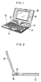
- Fig. 1 is an explanatory diagram showing an example of a lap-top type personal computer according to an embodiment of a computer apparatus of the invention.
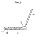
- Fig. 2 is a left side elevational view and
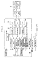
- Fig. 3 is a right side elevational view.
- the computer apparatus as a lap-top type personal computer is constructed by: a computer main body 10 having a keyboard 24; and a cover portion 28 which can be freely opened or closed for the computer main body 10 by a hinge 26.
- a liquid crystal display 30 is provided on the inside of the cover portion 28 so as to face front side in the open state shown in the diagram.
- a power switch 32 is provided at a right rear position of the keyboard 24 of the computer main body 10. Further, a battery 34 is attached to the thick portion behind the power switch 32. A chargeable type battery can be used as a battery 34 and the battery 34 can be automatically charged while the computer apparatus is used by a commercially available AC power source.
- a main switch 36 is provided on the side surface of the computer main body 10 as a root portion of the cover portion 28.
- a DC connector 38 is provided on the left side of the main switch 36.
- An output terminal of an AC adapter which will be clearly explained hereinlater, is connected to the DC connector 38.
- the computer main body 10 is automatically switched to the external power source mode in which the computer operates by using the commercially available AC power source.
- a small magnetic disk device 12 which is used as an "external" storage device is attached to (built into) side of the computer main body 10.
- a hard disk (HDD) of, for instance, a diameter of 2.5 inches and a memory capacity of about 40 Mbytes is used as a small magnetic disk device 12.
- An IC card 40 can be attached to the side of the computer main body 10.
- the IC card 40 is a memory medium having what is called a semiconductor memory therein and can be freely attached into or detached from the computer main body 10 as necessary. As shown in the diagram, the IC card 40 attached into the computer main body 10 can be detached by depressing an eject button 42.
- Fig. 4 is an embodiment constructional diagram showing an embodiment of the computer main body 10 as a lap-top type personal computer shown in Figs. 1 to 3.
- a CPU 45 is provided in the computer main body 10.
- An internal bus 44 is led out from the CPU 45.
- An ROM 46 in which a control program is stored and an RAM 48 to temporarily store and hold data are provided for the CPU 45.
- the LCD 30 is connected through a display controller 50.
- the display controller 50 displays image data stored in a video RAM (VRAM) 52.
- the keyboard 24 is also connected to the CPU 45 through a keyboard controller 54.
- an IC card controller 56 its input/output interface 58; a controller 60; its input/output interface 62; a printer controller 64; and its input/output interface 66.
- the magnetic disk device 12 as an external storage device is connected to the I/O interface 62 of the controller 60.
- the magnetic disk device 12 is constructed by an interface 68 and a disk device main body 70.
- a power source circuit 72 is provided in the computer main body 10.
- the DC connector 38 and battery 34 are connected to the power source circuit 72.
- An output plug 76 of an AC adapter 74 is connected to the DC connector 38.
- a commercially available AC voltage applied to the AC adapter 74 is converted into a specified DC voltage and supplied to the output plug 76.
- the power source circuit 72 receives the DC voltage supply from the AC adapter 74 or battery 34 and converts into a power source voltage which is necessary for each component and generates.
- the power source circuit 72 also supplies a power source to the magnetic disk device 12.
- a power source kind detecting section 14 to detect the kind of power source which is used at present is also further provided in the power source circuit 72.
- the detecting section 14 In a connecting state of the adapter 74, the detecting section 14 generates a power source mode signal indicative of the external power source mode.
- the detecting section 14 In a detaching state of the AC adapter 74, the detecting section 14 generates a power source mode signal indicative of the internal power source mode.
- a battery mode signal E0 is supplied as a power source mode signal to the internal bus 44.
- the battery mode signal E0 is set to 1 in the internal power source mode and to 0 in the external power source mode.
- the battery mode signal E0 from the power source circuit 72 is directly supplied to the magnetic disk device 12 through the internal bus 44, controller 60, and interface 62.
- the battery mode signal E0 is assigned to either one of the connector pins which are not ordinarily used.
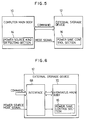
- Fig. 5 shows a block diagram of the computer apparatus of Fig. 4.
- the computer apparatus is constructed by the computer main body 10 which is operated by the commercially available AC power source or the battery power source provided in the apparatus and the external storage device 12 which is operated by receiving the power supply from the computer main body 10.
- a common housing may be provided for both units.
- the power source type detecting section 14 is provided in the computer main body 10. When the use of the external power source is detected, the detecting section 14 generates a power mode signal indicative of the external power source mode. When the use of the battery power source is detected, the detecting section 14 generates the power source mode signal indicative of the internal power source mode.
- a power save control section 16 is provided for the external storage device 12. When the power save command received from the computer main body 10 is executed, the power save control section 16 discriminates the power source mode signal from the power source kind detecting section 14. When the external power source mode is discriminated, the control section 16 inhibits the power save process to shut off the power supply to a predetermined circuit section even when the power save command exists. When the internal power source mode is discriminated, the control section 16 executes the power save process to shut off the power supply to a predetermined circuit section in accordance with the power save command.
- Fig. 6 shows a principle construction of the external storage device of Fig. 4.
- the external storage device 12 is a disk device and comprises: the interface 68 which receives the power source mode signal indicative of the use of the external power source or the use of the battery power source in addition to a control command from the high-order apparatus; and the power save control section 16 for discriminating the power source mode signal from the interface 68 when the power save command is received from the high-order apparatus and for processing.
- the power save control section 16 inhibits the power save process to shut off the power supply to a predetermined circuit section even if the power save command exists.
- the control section 16 executes the power save process to shut off the power supply to a predetermined circuit section in accordance with the power save command.
- Fig. 7 is an embodiment constructional diagram showing an embodiment of the power source kind detecting section 14 provided for the power source circuit 72 in Fig. 4.
- the DC connector 38 is connected to the power source kind detecting section 14.
- the DC connector 38 is formed by a central conductor 78 and a connecting member 80 having a bend portion at an edge. Two contact members 82 and 84 are come into contact with the connecting member 80 in an open state shown in the diagram, thereby setting both of them into a short-circuit state.
- the central conductor 78 of the DC connector 38 is connected to a minus line of the battery 34.
- the connecting member 80 is connected to a plus line.
- the contact member 82 is connected to a plus terminal of the battery 34.
- the contact member 82 is connected to the minus line through a resistor R1.
- the battery mode signal E0 is taken out from both ends of the resistor R1.
- the output plug 76 from the AC adapter 74 is connected to the DC connector 38.
- the output plug 76 comprises: a central conductor 86 having a hole to insert the central conductor 78 on the side of the DC connector 38; and an external conductor 90 which is come into contact with the connecting member 80 through an insulating member 88 on the outside of the central conductor 86.
- the connecting member 80 When the output plug 76 is inserted into the DC connector 38, the connecting member 80 is pushed up by the external conductor 90 on the plug side, thereby disconnecting the contact members 82 and 84. When the contact members 82 and 84 are away from the connecting member 80, the battery 34 is disconnected from the plus line and is also disconnected from the plus line of the resistor R1. Thus, the battery mode signal E0 changes to the zero volt from the battery volt of the battery 34 so far.
- the battery mode signal E0 when the battery mode signal E0 is checked from a viewpoint of the logic level, it is set into the logic level 1 by the supply of the internal power source from the battery 34 in the open state of the DC connector 38 shown in the diagram.
- the signal E0 is set into the logic level 0 by switching to the supply of the external power source based on the commercially available AC power source by inserting the output plug 76.
- a series circuit of a resistor R2 and a diode D1 is connected to the plus terminal of the battery 34 from the plus line of the power source kind detecting section 14.
- the battery 34 can be charged in the supply state of the external power source by the connection of the output plug 76.
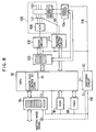
- Fig. 8 is an embodiment constructional diagram showing an embodiment of the magnetic disk device 12 connected to the computer main body 10 shown in Fig. 4.
- an MPU 92 is provided as a control section for the magnetic disk device.
- the MPU 92 has a function of the power save control section 16 to execute the power save control of the invention by a program control.
- An interface register file 94 to transmit and receive command data to/from the computer main body through an interface is provided on the left side of the MPU 92. Further, an ROM 96 in which the control program has been stored and an RAM 98 to temporarily store flags which are used for controls, which will be explained hereinlater, and data are provided.
- a servo control register file 100 is provided on the driving side as a right side of the MPU 92.
- a servo circuit 102 for VCM and a servo circuit 104 for a spindle motor are provided for the servo control register file 100.
- the servo circuit 102 for VCM drives a VCM (voice coil motor) 108 provided on the side of a disk enclosure (DE) 106.
- the VCM 108 performs a positioning control of a magnetic head 112 provided for a magnetic disk 110 as a recording medium which is rotated by a spindle motor 18.
- the servo circuit 104 for the spindle motor rotates the spindle motor 18 provided in the disk enclosure 106 at a constant speed of, e.g., 3600 r.p.m..
- a reading/writing circuit 114 is provided on the right side of the MPU 92. Either one of the magnetic heads 112 in the disk enclosure 106 is selected and data is written to the magnetic disk 110 or the data is read out from the magnetic disk 110.
- the power supply to the magnetic disk device as mentioned above is executed by a power source line shown by bold lines.
- a power source line 116 from the computer main body is directly connected to the MPU 92, interface register file 94, ROM 96, and RAM 98.
- a power source line 118 from a switching circuit 20 is connected to each circuit section on the right side of the MPU 92.
- the switching circuit 20 is turned off, the power supply to the power source line 118 is shut off and it is possible to stop the power supply to the servo control register file 100, servo circuits 102 and 104, reading/writing circuit 114, and spindle motor 18 and VCM 108 of the disk enclosure 106.
- the switching circuit 20 is controlled by a control output when the power save control section 16 of the MPU 92 receives the power save designation command from the computer main body 10 side.
- the battery mode signal E0 generated from the power source kind detecting section 14 on the computer main body 10 side is given to the interface register file 94 by using either one of the "RESERVED" pins which are not ordinarily used.
- the battery mode signal E0 is given to the MPU 92 through the interface register file 94. By checking the battery mode signal E0, the MPU 92 can know whether the power source used on the computer main body 10 side is the external power source or the internal power source.
- the battery mode signal E0 is directly given to the switching circuit 20 as shown by a broken line. As will be explained by an embodiment later, the gate circuit is controlled by the battery mode signal E0, thereby enabling the power save mode to be made valid or invalid by the MPU 92.
- the power save control section 16 provided in the MPU 92 receives the power save designation command from the computer main body and executes the power save control.
- Fig. 9 is an explanatory diagram showing a list of the kinds of power save designation commands which are received by the power save control section 16 and the contents of the commands.
- Fig. 9 there are five kinds of power save designation commands 0 to 4.
- the value of a sector count register which is set simultaneously with each command is ignored without being referred.
- the values of the sector count registers are referred and different processes according to the contents of the commands are executed.
- the commands 0 and 1 belong to the first power save mode.
- the commands 2 and 3 belong to the second power save mode which is known as an auto power save mode.
- the command 4 is used to check the current mode of the magnetic disk device.
- the sector count register is a counter which is used to store the number of sectors from the start address in the writing/reading mode.
- the sector count register is also commonly used for the power save process. That is, by setting the value of the sector count register to 0, the auto power save mode is set and reset. By setting the value of the sector count register to a value other than 0, the auto power save mode is set. For this purpose, there is determined a set time of the power save timer which is used to monitor that no command is accepted for a predetermined time.
- the command 0 is a power save set command to immediately shift the driving side to the power save mode.
- the command 1 is generated in the power save state and shifts from the power save mode to the idle mode. In this instance, if the auto power save mode has been set, the auto power save mode is reset.
- the control mode is immediately shifted to the power save mode.
- the value of the sector count register when it is equal to 0, the auto power save when the control mode is returned from the auto power save to the idle mode is not permitted.
- the value of the sector count register is equal to a value other than 0, the auto power save after the control mode was shifted from the power save mode to the idle mode is permitted.
- the command 3 is a reset command to return from the power save mode.
- the control mode is immediately shifted from the power save mode to the idle mode.
- the value of the sector count register is referred.
- the value of the sector count register is equal to 0 even when the control mode is shifted to the idle mode, the auto power save is not permitted.
- the value of the sector count register is equal to a value other than 0, the auto power save is permitted when the control mode is shifted to the idle mode.
- the control mode can be immediately set into the auto power save mode.
- the time of the timer which is used in the auto power save is set.
- the value of the sector count register other than 0 is set into the timer which is used to monitor the time of the auto power save.
- An arbitrary time in a range, for instance, from 15 seconds to 1275 seconds (21.1 minutes) can be set into the timer which is used to monitor the time of the auto power save mode.
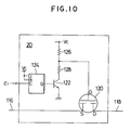
- Fig. 10 is an embodiment constructional diagram showing an embodiment of the switching circuit 20 which is turned on/off by the MPU 92 in Fig. 8.
- an FET 120 which functions as a switch is provided between the power source line 116 on the input side and the power source line 118 on the output side.
- a gate G of the FET 120 is connected to a node of a voltage dividing circuit of registers 126 and 128.
- a transistor 122 is further serially connected to the resistors 126 and 128.
- V C a power source voltage
- the FET 120 is turned off.
- the transistor 122 is turned on, the voltage of the gate G drops to the value of the voltage divided by the resistors 126 and 128 and the voltage V SG between the source and the gate increases, so that the FET 120 is turned on.
- a JK-FF 124 as a latch circuit is provided on the input side of the transistor 122. J and K terminals of the JK-FF 124 are pulled up to the power source voltage V C and fixed to the logic level 1. Therefore, an output Q is repetitively inverted each time a pulse is supplied to a clock terminal C.
- a control signal E1 for a power save control from the MPU 92 is given to the clock terminal C of the JK-FF 124 synchronously with the clock.
- JK-FF 124 is reset
- the transistor 122 is turned off
- the FET 120 is also turned off, thereby shutting off the power supply to the power source line 118.
- the JK-FF 124 is set, the transistor 122 is turned on, and the FET 120 is also turned on, thereby supplying the power source to the power source line 118.
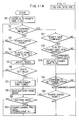
- step S1 an auto power save flag is first cleared in step S1.
- step S2 The presence or absence of the command reception is checked in step S2.
- step S3 follows and a check is made to see if the control mode has been set to the power save mode or not. If NO, step S4 follows and a check is made to see if the auto power save flag has been set or not.
- the auto power save flag is set in step S13 subsequent to step S11, which will be explained hereinlater.
- step S15 When it is discriminated in step S4 that the auto power save flag has been set, step S15 follows and a timer (software timer) which is used to discriminate the elapse of a predetermined time in the standby state of the auto power save is updated.
- step S6 a check is made to see if the updated timer value has reached a preset value or not. So long as a command is not received, the processes in steps S2 to S6 are repeated until the timer value reaches the set value.
- the power save process is executed only in the internal power source mode in which the battery is used as a power source. In case of the external power source mode in which the commercially available AC power source is used, the power save process is not executed on the magnetic disk apparatus side.
- step S11 follows.
- the MPU 92 discriminates the kind of command received, thereby checking to see if the command is the power save command or not.
- step S12 follows and the presence or absence of the designation of the auto power save by the power save command is checked.
- the auto power save is designated when the value of the sector count register SC is equal to a value other than 0 with respect to the commands 2 and 3 in Fig. 9.
- step S13 follows and the auto power save flag is set.
- step S14 directly follows.
- step S14 A check is made in step S14 to see if the command is a command to immediately set into the power save mode or not.
- the command to set into the power save mode is either the command 0 or 2.
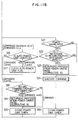
- step S15 follows and a check is made to see if the power save mode has been set or not. If NO, step S7 follows and the power save timer is cleared. After that, in step S8, the battery mode signal is read. In a manner similar to the case where the auto power save flag has been set, only in case of the internal power source mode in step S9, the processing routine advances to step S10 and the power save process is executed.
- step S18 follows and a check is made to see if the command is a command to return from the power save mode or not. Since the return command is either the command 1 or 3, in this instance, step S19 follows and the returning process from the power save mode, which will be explained hereinlater, is executed. In step S20, the power save timer is cleared and, after that, the processing routine is returned to step S2.
- the command is other than the return command from the power save mode in step S18, namely, when it is the command 4, the returning process in step S19 is not executed.
- step S11 When the command reception is detected in step S2, a check is made in step S11 to see if the command is the power save command or not. In this case, since it is not the power save command, step S21 follows. In step S21, a check is made to see if the power save mode has been set or not. If YES, a check is made in step S22 to see if it is necessary to return from the power save mode or not upon execution of the relevant command.
- step S23 follows and the returning process from the power save mode, which will be explained hereinlater, is executed.
- step S24 the command is executed.
- the power save timer is cleared in step S50 and the processing routine is again returned to step S2.
- step S50 by clearing the power save timer after completion of the execution of the command other than the power save command, when the processing routine is returned to the step S2 side, a process to set into the power save mode by monitoring that no command is generated from the high-order apparatus for a predetermined time is newly started.
- step S10 in Fig. 11 The power save process in step S10 in Fig. 11, the returning process from the power save mode in step S19, and the returning process from the power save mode in step S23 are executed by subroutines A and B, which will be described later.
- Fig. 12 is a flowchart showing the subroutine A of the power save process in step S10 in Fig. 11.
- a stop command to the spindle motor 18 is first set in step S100.
- a power save command is generated to the switching circuit 20 in step S101.
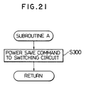
- Fig. 13 is a flowchart showing another embodiment of the subroutine A to execute the power save process in step S10 in Fig. 11.
- the head present position register is first read in step S100 and stored into the RAM 98 in step S101. After that, a movement command to a cylinder "0" is generated in step S102. Subsequently, a check is made in step S103 to see if the seeking operation to the cylinder "0" has been completed or not. After that, in step S104, the stop command of the spindle motor 18 is set. Further, the servo control register file 100 is cleared in step S105. Finally, the power save command is supplied to the switching circuit 20 in step S106.
- the movement command to move the head to the cylinder "0" has been generated, it is also possible to move the head to a head landing zone. In such a case, the head can be moved to the head landing zone by merely setting the movement command to the head landing zone.
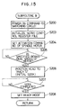
- Fig. 14 is a flowchart showing an embodiment of the subroutine B as a returning process from the power save mode in steps S19 and S23 in Fig. 11 and relates to the returning process in the case where the power save is executed as a power save process by the subroutine A in Fig. 12.
- a power turn-on command is first supplied to the switching circuit 20 in step S200.
- the servo control register file 100 is read in step S201.
- step S202 a check is made to see if the power save mode has been set or not. If YES, step S203 follows and the servo control register file 100 is initialized. After that, in step S204, a start command of the spindle motor 18 is set to activate the spindle motor 18. A check is made in step S205 to see if a rotational speed of the motor has reached a specified speed or not (by monitoring the elapsed time or by detecting the rotational speed of the spindle motor 18).
- step S206 When the rotational speed of the spindle motor 18 reaches the specified speed, the processing routine advances to step S206 and an initial seeking operation to position the head to the track "0" is executed. A check is made in step S207 to see if the initial seeking operation has been completed or not. If YES, a ready mode is set in step S208, thereby enabling the operation to be executed.
- Fig. 15 shows the second embodiment of the subroutine B as a returning process from the power save mode in steps S19 and S23 in Fig. 11 and corresponds to the power saving process according to the second embodiment of the subroutine A shown in Fig. 13.
- step S203 the power turn-on command is first supplied to the switching circuit 20 in step S200, thereby starting the power supply.
- the servo control register file 100 is initialized.
- step S204 the start command of the spindle motor 18 is set to activate the motor.
- step S205 the initial seeking operation to position the head to the track "0" is executed in step S206.
- step S207 the ready state is set in step S208.
- steps S100 and S101 in the subroutine A in Fig. 13 since the head present position register has already been read and stored in the RAM, in the returning process by the subroutine B of Fig. 15, it is also possible to read out the value of the head present position register from the RAM after the ready mode was set in step S208 and to seek the head to such a position.
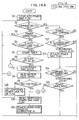
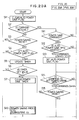
- Figs. 16 and 17 are flowcharts showing a modification of the power save control of the invention shown in Fig. 11.
- the processes in steps S1 to S24 are fundamentally similar to those in the embodiment of Fig. 11 and processes in steps S25 to S30 are newly added as well as the above processes.
- Figs. 18A and 18B are explanatory diagrams showing a difference between the processes in Fig. 10 and the processes in Figs. 16 and 17.
- Fig. 18A shows check timings of the battery mode signal in the set state of the auto power save flag in Fig. 11.
- the set time T of the power save timer is set to a relatively long time such as a time from 15 seconds to about 21 minutes. Therefore, for instance, in a set state of the auto power save flag, even when the using state of the power source is changed from the external power source mode so far to the internal power source mode, the battery mode signal is not checked until the power save timer reaches the set time T. Consequently, a time delay occurs until the control mode is set to the power save mode in the internal power source mode.
- the first set time T after the power save flag was set is the same as that in the case of Fig. 11.
- the battery mode signal can be checked at a time interval shorter than the set time T.
- the control mode can be immediately shifted to the power save mode.
- step S12 the designation of the auto power save is discriminated in step S12.
- the auto power save flag is set in step S13.
- step S14 the command 2 to set into the power save mode is discriminated in step S14.
- the processing routine advances to step S27 in Fig. 16 and the battery mode signal is read.
- the processing routine is again returned to step S2 in Fig. 16.
- step S4 A check is subsequently made in step S4 to see if the auto power save flag has been set or not through step S3.
- the timer is updated in step S5.
- step S6 a check is made in step S6 to see if the value of the timer has reached the set value or not. If NO, step S26 in Fig. 17 follows and a check is made to see if a temporary power save mode has been set or not. In this instance, since the temporary power save mode is not set, the processing routine is again returned to step S2 and the processes similar to the above are repeated.
- step S6 when it is determined in step S6 that the timer has reached the set value, the power save timer is cleared in step S7. After that, the battery mode signal is read in step S8. When the battery mode signal doesn't indicate the internal power source mode, the processing routine advances from step S9 to step S25 and the temporary power save mode flag is set and the updating period of time by the next power save timer is started.
- step S6 the processing routine advances to step S26 in Fig. 17 and a check is made to see if the temporary power save mode has been set or not.
- the battery mode signal is read in step S27.
- a check is made in step S28 to see if the power mode indicates the internal power source mode or not.
- step S28 when the power mode is switched from the external power source mode so far to the internal power source mode for a time interval until the power save timer reaches the set time, a check is made in step S28 to see if the power mode indicates the internal power source mode or not from the result of the reading of the battery mode signal in step S27.
- the power save timer is cleared in step S29. After that, the temporary power save mode flag is reset in step S30 in Fig. 15 and step S10 follows and the power save mode process is immediately started.
- Fig. 19 is an embodiment constructional diagram showing the second embodiment of the switching circuit 20 which is used in the magnetic disk device in Fig. 8.
- constructions of the voltage dividing circuit comprising the FET 120 and resistors 126 and 128, the transistor 122, and the JK-FF 124 are substantially the same as those in the first embodiment of Fig. 10.
- an NAND circuit 22 as a gate circuit which is controlled by the battery mode signal E0 is provided between the JK-FF 124 and the transistor 122.
- An output of the JK-FF 124 is supplied to a base of the transistor 122 through the NAND circuit 22.
- the transistor 122 is, accordingly, turned on and the FET 120 is also turned on, thereby restarting the power supply to the power source line 118.
- the NAND circuit 22 which is controlled by the battery mode signal E0 is provided for the switching circuit 20 and the control signal E1 is made valid or invalid in accordance with the power save command from the MPU 92 by a hardware manner, so that it is unnecessary to execute a checking process of the battery mode signal on the MPU 92 side.
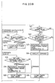
- Fig. 20 is a flowchart showing the power save control by the MPU 92 in case of using the switching circuit 20 in Fig. 19.
- the reading process of the battery mode signal in step S8 in Fig. 11 and the discriminating process of the internal power source mode in step S9 are omitted.
- the other processes are similar to those in Fig. 11.
- the power save control which is executed by the magnetic disk apparatus in accordance with the power save designation command from the computer main body 10 is not limited to the above embodiment but a proper power save control can be executed as necessary.
- the kind of power source which is used by the apparatus is detected and can be recognized on the external storage device side. Even when the power save designation command is received from the computer main body, the power save mode is set only in the internal power source mode, thereby suppressing the electric power consumption of the battery. On the other hand, in the external power source mode, even when the power save designation command is received, the power save mode is not set but the stop of the spindle motor by setting the power save mode is started, thereby preventing an increase in number of contact start/stop (CSS) times and an increase in number of stop and activation times of the spindle motor. The lives of the disk medium and spindle motor can be maintained.
- SCS contact start/stop
- the power save mode is not set. Therefore, a deterioration of the throughput of the apparatus because the time which is required until the end of the execution when the access is received in the power save mode becomes long can be prevented.
- the term "external" when applied to the storage device does not necessarily mean that the storage device is physically separate from the computer apparatus. It also refers to a storage device provided in the same housing as the computer apparatus.
- main body does not necessarily imply the presence of a housing but can also refer to a module, main circuit board or the like.
Landscapes
- Engineering & Computer Science (AREA)
- Theoretical Computer Science (AREA)
- Physics & Mathematics (AREA)
- General Engineering & Computer Science (AREA)
- General Physics & Mathematics (AREA)
- Power Sources (AREA)
- Calculators And Similar Devices (AREA)
Applications Claiming Priority (2)
| Application Number | Priority Date | Filing Date | Title |
|---|---|---|---|
| JP168336/91 | 1991-07-09 | ||
| JP03168336A JP3096489B2 (ja) | 1991-07-09 | 1991-07-09 | ディスク装置 |
Publications (3)
| Publication Number | Publication Date |
|---|---|
| EP0522483A2 true EP0522483A2 (fr) | 1993-01-13 |
| EP0522483A3 EP0522483A3 (en) | 1993-12-22 |
| EP0522483B1 EP0522483B1 (fr) | 1999-02-10 |
Family
ID=15866168
Family Applications (1)
| Application Number | Title | Priority Date | Filing Date |
|---|---|---|---|
| EP92111420A Expired - Lifetime EP0522483B1 (fr) | 1991-07-09 | 1992-07-06 | Ordinateur et dispositif de mémoire ayant un dispositif de mémoire d'économie d'énergie contrÔlé |
Country Status (5)
| Country | Link |
|---|---|
| US (1) | US5652891A (fr) |
| EP (1) | EP0522483B1 (fr) |
| JP (1) | JP3096489B2 (fr) |
| KR (1) | KR970000275B1 (fr) |
| DE (1) | DE69228408T2 (fr) |
Cited By (7)
| Publication number | Priority date | Publication date | Assignee | Title |
|---|---|---|---|---|
| EP0647044A3 (fr) * | 1993-08-05 | 1995-07-05 | Fujitsu Ltd | ContrÔleur de communication et procédé de contrÔle de communication. |
| EP0679983A3 (fr) * | 1994-04-26 | 1998-12-09 | International Business Machines Corporation | Dispositif d'extension avec fonction d'arrêt/reprise |
| WO1999061974A1 (fr) * | 1998-05-28 | 1999-12-02 | Phoenix Technologies Ltd. | Emulation logicielle d'un controle de l'inactivite de la gestion de la puissance |
| EP1089159A3 (fr) * | 1999-09-30 | 2003-10-22 | Kabushiki Kaisha Toshiba | Appareil terminal portatif de traitement d'informations à faible consommation d'énergie et grande capacité de mémoire |
| SG101464A1 (en) * | 2000-08-29 | 2004-01-30 | Sony Corp | Electronic apparatus and external apparatus using the same |
| EP1533814A4 (fr) * | 2002-06-28 | 2006-11-22 | Fujitsu Ltd | Dispositif de stockage d'informations |
| EP1450240A3 (fr) * | 2003-01-31 | 2012-11-07 | Microsoft Corporation | Procédé et dispositif pour la gestion energetique dans modules d'interface réseau |
Families Citing this family (39)
| Publication number | Priority date | Publication date | Assignee | Title |
|---|---|---|---|---|
| US5182546A (en) * | 1988-02-12 | 1993-01-26 | Canon Kabushiki Kaisha | Electronic apparatus which can discriminate between different power sources which it uses |
| JP2776105B2 (ja) * | 1992-01-07 | 1998-07-16 | 三菱電機株式会社 | 電子機器及び電子機器への電力供給方法 |
| EP1674974A3 (fr) * | 1994-06-07 | 2007-03-21 | Hitachi, Global Storage Technologies Japan, Ltd. | Appareil pour l'emmagasinage d'information |
| JP3080875B2 (ja) * | 1996-02-29 | 2000-08-28 | 株式会社東芝 | コンピュータシステムおよびその節電方法 |
| US6295569B1 (en) * | 1996-05-20 | 2001-09-25 | Fujitsu Limited | Storage apparatus |
| US6401847B1 (en) | 1996-11-08 | 2002-06-11 | Case Corporation | Vehicle track undercarriage adjustment system |
| US6275945B1 (en) * | 1996-11-26 | 2001-08-14 | Kabushiki Kaisha Toshiba | Apparatus for radiating heat for use in computer system |
| US5884049A (en) * | 1996-12-31 | 1999-03-16 | Compaq Computer Corporation | Increased processor performance comparable to a desktop computer from a docked portable computer |
| KR100262518B1 (ko) * | 1997-07-09 | 2000-08-01 | 윤종용 | 시스템상태를감지할수있는전원분배유닛 |
| JP4343282B2 (ja) * | 1998-02-10 | 2009-10-14 | 富士通株式会社 | 複合通信端末装置管理システム及び複合通信端末装置 |
| WO2000028402A1 (fr) * | 1998-11-09 | 2000-05-18 | Seiko Epson Corporation | Dispositif d'interface, procede de commande de dispositif d'interface, et dispositif d'enregistrement d'informations |
| US6272642B2 (en) * | 1998-12-03 | 2001-08-07 | Intel Corporation | Managing a system's performance state |
| JP2000214966A (ja) * | 1999-01-20 | 2000-08-04 | Ricoh Co Ltd | 携帯型情報処理装置 |
| US6353894B1 (en) * | 1999-04-08 | 2002-03-05 | Mitsumi Electric Co., Ltd. | Power management system |
| US6523124B1 (en) * | 1999-04-23 | 2003-02-18 | Palm, Inc. | System and method for detection of an accessory device connection status |
| US6418535B1 (en) | 1999-04-28 | 2002-07-09 | International Business Machines Corporation | Bi-level power saver method for portable or laptop computer |
| US6691098B1 (en) | 2000-02-08 | 2004-02-10 | International Business Machines Corporation | System and method for explaining exceptions in data |
| US6910139B2 (en) * | 2000-10-02 | 2005-06-21 | Fujitsu Limited | Software processing apparatus with a switching processing unit for displaying animation images in an environment operating base on type of power supply |
| KR20020096584A (ko) * | 2001-06-21 | 2002-12-31 | 기장 메디칼 주식회사 | 전자쑥뜸기의 전원공급 겸용 컴퓨터 |
| JP2003044177A (ja) * | 2001-07-12 | 2003-02-14 | Internatl Business Mach Corp <Ibm> | コンピュータ装置、電源制御装置、電源管理方法 |
| US6544200B1 (en) | 2001-08-31 | 2003-04-08 | Bed-Check Corporation | Electronic patient monitor with automatically configured alarm parameters |
| US7114086B2 (en) * | 2002-01-04 | 2006-09-26 | Ati Technologies, Inc. | System for reduced power consumption by monitoring instruction buffer and method thereof |
| JP4219610B2 (ja) * | 2002-04-23 | 2009-02-04 | 株式会社日立製作所 | ディスクサブシステム装置 |
| JP3756882B2 (ja) * | 2003-02-20 | 2006-03-15 | 株式会社東芝 | 情報処理装置及び情報処理方法 |
| US7111180B2 (en) * | 2003-08-29 | 2006-09-19 | Dell Products L.P. | Information handling system interrupting current to external module if current exceeds different current limits when handling system receives current from battery and alternating current source |
| EP1566797B1 (fr) * | 2004-02-19 | 2008-04-23 | Samsung Electronics Co., Ltd. | Procédé de contrôle du mode repos d'unité de disque dur et appareil associe |
| JP2006114170A (ja) * | 2004-10-18 | 2006-04-27 | Funai Electric Co Ltd | 再生装置 |
| JP4607545B2 (ja) * | 2004-10-29 | 2011-01-05 | 株式会社東芝 | 情報処理装置および電力制御方法 |
| KR100605184B1 (ko) * | 2004-12-09 | 2006-07-31 | 엘지전자 주식회사 | 디지털 영상기기의 절전 모드 제어장치 및 방법 |
| US7836216B2 (en) * | 2005-08-23 | 2010-11-16 | Palm, Inc. | Connector system for supporting multiple types of plug carrying accessory devices |
| KR100790035B1 (ko) * | 2005-08-31 | 2008-01-02 | 엘지전자 주식회사 | 전원제어장치 및 방법 |
| JP4798037B2 (ja) * | 2006-03-31 | 2011-10-19 | パナソニック株式会社 | ハードディスクドライブ状態監視装置およびハードディスクドライブ状態監視方法 |
| US20070250725A1 (en) * | 2006-04-20 | 2007-10-25 | Pang-Chiang Chia | Power Saving Device for an Actuator |
| US7734841B2 (en) * | 2006-06-30 | 2010-06-08 | Palm, Inc. | System and method for providing serial bus connectivity |
| FI20065783A0 (sv) * | 2006-12-08 | 2006-12-08 | Nokia Corp | Signalfördistorsion i radiosändare |
| WO2008072327A1 (fr) * | 2006-12-14 | 2008-06-19 | Fujitsu Limited | Dispositif de stockage et procédé de commande d'économie d'énergie pour celui-ci |
| JP2009266178A (ja) * | 2008-04-30 | 2009-11-12 | Fujitsu Ltd | 中継装置および中継システム |
| JP4963715B2 (ja) * | 2009-06-10 | 2012-06-27 | レノボ・シンガポール・プライベート・リミテッド | 電子機器、そのバッテリ使用可能時間の表示方法、およびコンピュータが実行可能なプログラム |
| JP4935918B2 (ja) * | 2010-03-29 | 2012-05-23 | 株式会社日立製作所 | 情報記録装置 |
Family Cites Families (23)
| Publication number | Priority date | Publication date | Assignee | Title |
|---|---|---|---|---|
| GB1545169A (en) * | 1977-09-22 | 1979-05-02 | Burroughs Corp | Data processor system including data-save controller for protection against loss of volatile memory information during power failure |
| JPS5955526A (ja) * | 1982-09-24 | 1984-03-30 | Sharp Corp | インタ−フエ−ス回路 |
| JPS59127266A (ja) * | 1983-01-07 | 1984-07-23 | Canon Inc | 情報再生装置 |
| US4573117A (en) * | 1983-11-07 | 1986-02-25 | Motorola, Inc. | Method and apparatus in a data processor for selectively disabling a power-down instruction |
| US4669059A (en) * | 1983-11-07 | 1987-05-26 | Motorola, Inc. | Method and apparatus in a data processor for selectively disabling a power-down instruction |
| US4651237A (en) * | 1984-06-28 | 1987-03-17 | Zilog, Inc. | Programmed disk controller capable of operating with a variety of data encoding techniques |
| US4757505A (en) * | 1986-04-30 | 1988-07-12 | Elgar Electronics Corp. | Computer power system |
| JPS63100555A (ja) * | 1986-10-17 | 1988-05-02 | Hitachi Ltd | 情報記録再生装置 |
| US4916557A (en) * | 1987-02-27 | 1990-04-10 | Kabushiki Kaisha Toshiba | Method of sharing various types of medium drives and recording/reproduction apparatus with medium controller for realizing the method |
| US5182546A (en) * | 1988-02-12 | 1993-01-26 | Canon Kabushiki Kaisha | Electronic apparatus which can discriminate between different power sources which it uses |
| US5012406A (en) * | 1988-04-19 | 1991-04-30 | Power Card Supply | Line of power interruption in predetermined area of internal permanent memory |
| US4980836A (en) * | 1988-10-14 | 1990-12-25 | Compaq Computer Corporation | Apparatus for reducing computer system power consumption |
| JPH02176920A (ja) * | 1988-12-28 | 1990-07-10 | Canon Inc | 電子機器 |
| JPH02260997A (ja) * | 1989-03-31 | 1990-10-23 | Toshiba Corp | 入出力切換回路 |
| FR2645988A1 (fr) * | 1989-04-14 | 1990-10-19 | Altec Sa | Dispositif pour branchement d'un disque dur amovible |
| JPH0311413A (ja) * | 1989-06-08 | 1991-01-18 | Nec Corp | 電源切断機構 |
| US4991129A (en) * | 1989-07-25 | 1991-02-05 | Areal Technology, Inc. | Dual mode actuator for disk drive useful with a portable computer |
| US5167024A (en) * | 1989-09-08 | 1992-11-24 | Apple Computer, Inc. | Power management for a laptop computer with slow and sleep modes |
| JPH03109625A (ja) * | 1989-09-22 | 1991-05-09 | Toshiba Corp | 電子機器 |
| JP2877378B2 (ja) * | 1989-09-29 | 1999-03-31 | 株式会社東芝 | パーソナルコンピュータ |
| US5021983B1 (en) * | 1989-11-13 | 1996-05-28 | Chips & Technologies Inc | Suspend/resume apparatus and method for reducing power consumption in battery powered computers |
| JP3245861B2 (ja) * | 1990-11-19 | 2002-01-15 | セイコーエプソン株式会社 | ドッキングシステム |
| JP3701965B2 (ja) * | 1991-05-17 | 2005-10-05 | 日本電気株式会社 | 保護モードマイクロプロセッサ及びハードディスクのための中断/再開機能とアイドルモードの実現 |
-
1991
- 1991-07-09 JP JP03168336A patent/JP3096489B2/ja not_active Expired - Fee Related
-
1992
- 1992-07-06 EP EP92111420A patent/EP0522483B1/fr not_active Expired - Lifetime
- 1992-07-06 DE DE69228408T patent/DE69228408T2/de not_active Expired - Fee Related
- 1992-07-09 KR KR1019920012225A patent/KR970000275B1/ko not_active Expired - Fee Related
-
1994
- 1994-07-22 US US08/279,259 patent/US5652891A/en not_active Expired - Fee Related
Cited By (14)
| Publication number | Priority date | Publication date | Assignee | Title |
|---|---|---|---|---|
| EP0647044A3 (fr) * | 1993-08-05 | 1995-07-05 | Fujitsu Ltd | ContrÔleur de communication et procédé de contrÔle de communication. |
| US5610593A (en) * | 1993-08-05 | 1997-03-11 | Fujitsu Limited | Communication controller and communication control method |
| EP0679983A3 (fr) * | 1994-04-26 | 1998-12-09 | International Business Machines Corporation | Dispositif d'extension avec fonction d'arrêt/reprise |
| WO1999061974A1 (fr) * | 1998-05-28 | 1999-12-02 | Phoenix Technologies Ltd. | Emulation logicielle d'un controle de l'inactivite de la gestion de la puissance |
| US6128745A (en) * | 1998-05-28 | 2000-10-03 | Phoenix Technologies Ltd. | Power management inactivity monitoring using software threads |
| GB2354123A (en) * | 1998-05-28 | 2001-03-14 | Phoenix Tech Ltd | Software emulations of power management inactivity monitoring |
| GB2354123B (en) * | 1998-05-28 | 2003-03-05 | Phoenix Tech Ltd | Software emulation of power management inactivity monitoring |
| EP1089159A3 (fr) * | 1999-09-30 | 2003-10-22 | Kabushiki Kaisha Toshiba | Appareil terminal portatif de traitement d'informations à faible consommation d'énergie et grande capacité de mémoire |
| SG101464A1 (en) * | 2000-08-29 | 2004-01-30 | Sony Corp | Electronic apparatus and external apparatus using the same |
| US6971035B2 (en) | 2000-08-29 | 2005-11-29 | Sony Corporation | Method and system for reducing power consumption of a multi-function electronic apparatus that is adapted to receive power from a host system |
| EP1533814A4 (fr) * | 2002-06-28 | 2006-11-22 | Fujitsu Ltd | Dispositif de stockage d'informations |
| EP1863029A1 (fr) * | 2002-06-28 | 2007-12-05 | Fujitsu Limited | Dispositif de stockage d'informations |
| US7373529B2 (en) | 2002-06-28 | 2008-05-13 | Fujitsu Limited | Performing a power supply check for an information storage device to increase power consumption in a stepwise manner |
| EP1450240A3 (fr) * | 2003-01-31 | 2012-11-07 | Microsoft Corporation | Procédé et dispositif pour la gestion energetique dans modules d'interface réseau |
Also Published As
| Publication number | Publication date |
|---|---|
| KR930002951A (ko) | 1993-02-23 |
| US5652891A (en) | 1997-07-29 |
| DE69228408T2 (de) | 1999-06-24 |
| DE69228408D1 (de) | 1999-03-25 |
| JPH0519915A (ja) | 1993-01-29 |
| KR970000275B1 (ko) | 1997-01-08 |
| EP0522483A3 (en) | 1993-12-22 |
| EP0522483B1 (fr) | 1999-02-10 |
| JP3096489B2 (ja) | 2000-10-10 |
Similar Documents
| Publication | Publication Date | Title |
|---|---|---|
| EP0522483B1 (fr) | Ordinateur et dispositif de mémoire ayant un dispositif de mémoire d'économie d'énergie contrÔlé | |
| US7057309B2 (en) | Electrical apparatus, computer, power switching unit, and power switching method | |
| EP0825519B1 (fr) | Méthode de contrôle de disque optique | |
| US6516374B1 (en) | Method for docking/undocking a portable computer to/from an expansion unit | |
| US7206944B2 (en) | Electrical apparatus, computer, and power switching method | |
| EP0471928B1 (fr) | Système et méthode de confirmation de l'état de connexion d'extension d'unité | |
| US5948074A (en) | Expansion unit having a security mechanism for inhibiting attachment and disconnection of the expansion unit to and from a portable computer | |
| EP0834796B1 (fr) | Système d'ordinateur et procédé de commande d'économie d'énergie | |
| US6052291A (en) | AC adaptor with power consumption reduction in unused state for a battery-operated electronic apparatus | |
| US7315955B2 (en) | Circuit for turning off charging function to a battery of a system based on information set by user during the system in power-off state | |
| US6088620A (en) | Computer system in which a high-order application program recognizes a power-on factor or a state of an expansion unit | |
| US20030204652A1 (en) | Data transfer control device, electronic equipment and data transfer control method | |
| US5832285A (en) | Battery powered computer capable of switching to a suspend mode based on the connection status of an external device | |
| US7929383B2 (en) | Notebook optical disc drive capable of generating a pseudo eject signal | |
| US6327635B1 (en) | Add-on card with automatic bus power line selection circuit | |
| EP0487900A1 (fr) | Ordinateur portable pour remise à zéro d'erreur de reprise causé par changement de condition de HDD-chargé et redémarrage de SO | |
| US5410712A (en) | Computer system equipped with extended unit including power supply | |
| JP2781512B2 (ja) | ディスク装置とその起動方法 | |
| EP0498374A2 (fr) | Ordinateur à fonction de processus de reprise | |
| US20030140262A1 (en) | Switching power planes of external device interfaces in a computing system in response to connection status | |
| US20070150765A1 (en) | Information processing apparatus having electronic device whose operating speed is controlled, and method of controlling the operating speed of the electronic device | |
| US20040057182A1 (en) | Method and control apparatus for controlling two hot-swapable IDE devices | |
| JPH06138985A (ja) | 拡張ユニットの電源制御回路 | |
| JP3133492B2 (ja) | 情報処理装置 | |
| JPH08161088A (ja) | 情報処理装置 |
Legal Events
| Date | Code | Title | Description |
|---|---|---|---|
| PUAI | Public reference made under article 153(3) epc to a published international application that has entered the european phase |
Free format text: ORIGINAL CODE: 0009012 |
|
| AK | Designated contracting states |
Kind code of ref document: A2 Designated state(s): DE FR GB |
|
| PUAL | Search report despatched |
Free format text: ORIGINAL CODE: 0009013 |
|
| AK | Designated contracting states |
Kind code of ref document: A3 Designated state(s): DE FR GB |
|
| 17P | Request for examination filed |
Effective date: 19940419 |
|
| 17Q | First examination report despatched |
Effective date: 19970520 |
|
| GRAG | Despatch of communication of intention to grant |
Free format text: ORIGINAL CODE: EPIDOS AGRA |
|
| GRAG | Despatch of communication of intention to grant |
Free format text: ORIGINAL CODE: EPIDOS AGRA |
|
| GRAH | Despatch of communication of intention to grant a patent |
Free format text: ORIGINAL CODE: EPIDOS IGRA |
|
| GRAH | Despatch of communication of intention to grant a patent |
Free format text: ORIGINAL CODE: EPIDOS IGRA |
|
| GRAA | (expected) grant |
Free format text: ORIGINAL CODE: 0009210 |
|
| AK | Designated contracting states |
Kind code of ref document: B1 Designated state(s): DE FR GB |
|
| REF | Corresponds to: |
Ref document number: 69228408 Country of ref document: DE Date of ref document: 19990325 |
|
| ET | Fr: translation filed | ||
| PLBE | No opposition filed within time limit |
Free format text: ORIGINAL CODE: 0009261 |
|
| STAA | Information on the status of an ep patent application or granted ep patent |
Free format text: STATUS: NO OPPOSITION FILED WITHIN TIME LIMIT |
|
| 26N | No opposition filed | ||
| REG | Reference to a national code |
Ref country code: GB Ref legal event code: IF02 |
|
| PGFP | Annual fee paid to national office [announced via postgrant information from national office to epo] |
Ref country code: GB Payment date: 20030702 Year of fee payment: 12 |
|
| PGFP | Annual fee paid to national office [announced via postgrant information from national office to epo] |
Ref country code: FR Payment date: 20030711 Year of fee payment: 12 |
|
| PGFP | Annual fee paid to national office [announced via postgrant information from national office to epo] |
Ref country code: DE Payment date: 20030717 Year of fee payment: 12 |
|
| PG25 | Lapsed in a contracting state [announced via postgrant information from national office to epo] |
Ref country code: GB Free format text: LAPSE BECAUSE OF NON-PAYMENT OF DUE FEES Effective date: 20040706 |
|
| PG25 | Lapsed in a contracting state [announced via postgrant information from national office to epo] |
Ref country code: DE Free format text: LAPSE BECAUSE OF NON-PAYMENT OF DUE FEES Effective date: 20050201 |
|
| GBPC | Gb: european patent ceased through non-payment of renewal fee |
Effective date: 20040706 |
|
| PG25 | Lapsed in a contracting state [announced via postgrant information from national office to epo] |
Ref country code: FR Free format text: LAPSE BECAUSE OF NON-PAYMENT OF DUE FEES Effective date: 20050331 |
|
| REG | Reference to a national code |
Ref country code: FR Ref legal event code: ST |