EP0522499B1 - Systéme de reproduction d'un milieu d'enregistrement optique avec détection précise de la position de piste - Google Patents
Systéme de reproduction d'un milieu d'enregistrement optique avec détection précise de la position de piste Download PDFInfo
- Publication number
- EP0522499B1 EP0522499B1 EP92111490A EP92111490A EP0522499B1 EP 0522499 B1 EP0522499 B1 EP 0522499B1 EP 92111490 A EP92111490 A EP 92111490A EP 92111490 A EP92111490 A EP 92111490A EP 0522499 B1 EP0522499 B1 EP 0522499B1
- Authority
- EP
- European Patent Office
- Prior art keywords
- signal
- optical
- track
- pits
- reproducing system
- Prior art date
- Legal status (The legal status is an assumption and is not a legal conclusion. Google has not performed a legal analysis and makes no representation as to the accuracy of the status listed.)
- Expired - Lifetime
Links
- 230000003287 optical effect Effects 0.000 title claims description 122
- 238000001514 detection method Methods 0.000 title description 9
- 238000003708 edge detection Methods 0.000 description 12
- 238000006243 chemical reaction Methods 0.000 description 6
- 238000010586 diagram Methods 0.000 description 6
- 238000000034 method Methods 0.000 description 6
- 230000000630 rising effect Effects 0.000 description 6
- 239000003990 capacitor Substances 0.000 description 4
- 230000007423 decrease Effects 0.000 description 3
- 230000007704 transition Effects 0.000 description 3
- 238000013459 approach Methods 0.000 description 2
- 230000001788 irregular Effects 0.000 description 2
- 230000015572 biosynthetic process Effects 0.000 description 1
- 230000003247 decreasing effect Effects 0.000 description 1
- 238000006073 displacement reaction Methods 0.000 description 1
- 230000012447 hatching Effects 0.000 description 1
- 239000004065 semiconductor Substances 0.000 description 1
Images



Classifications
-
- G—PHYSICS
- G11—INFORMATION STORAGE
- G11B—INFORMATION STORAGE BASED ON RELATIVE MOVEMENT BETWEEN RECORD CARRIER AND TRANSDUCER
- G11B7/00—Recording or reproducing by optical means, e.g. recording using a thermal beam of optical radiation by modifying optical properties or the physical structure, reproducing using an optical beam at lower power by sensing optical properties; Record carriers therefor
- G11B7/08—Disposition or mounting of heads or light sources relatively to record carriers
- G11B7/085—Disposition or mounting of heads or light sources relatively to record carriers with provision for moving the light beam into, or out of, its operative position or across tracks, otherwise than during the transducing operation, e.g. for adjustment or preliminary positioning or track change or selection
- G11B7/08505—Methods for track change, selection or preliminary positioning by moving the head
-
- G—PHYSICS
- G11—INFORMATION STORAGE
- G11B—INFORMATION STORAGE BASED ON RELATIVE MOVEMENT BETWEEN RECORD CARRIER AND TRANSDUCER
- G11B7/00—Recording or reproducing by optical means, e.g. recording using a thermal beam of optical radiation by modifying optical properties or the physical structure, reproducing using an optical beam at lower power by sensing optical properties; Record carriers therefor
- G11B7/08—Disposition or mounting of heads or light sources relatively to record carriers
- G11B7/085—Disposition or mounting of heads or light sources relatively to record carriers with provision for moving the light beam into, or out of, its operative position or across tracks, otherwise than during the transducing operation, e.g. for adjustment or preliminary positioning or track change or selection
-
- G—PHYSICS
- G11—INFORMATION STORAGE
- G11B—INFORMATION STORAGE BASED ON RELATIVE MOVEMENT BETWEEN RECORD CARRIER AND TRANSDUCER
- G11B7/00—Recording or reproducing by optical means, e.g. recording using a thermal beam of optical radiation by modifying optical properties or the physical structure, reproducing using an optical beam at lower power by sensing optical properties; Record carriers therefor
- G11B7/007—Arrangement of the information on the record carrier, e.g. form of tracks, actual track shape, e.g. wobbled, or cross-section, e.g. v-shaped; Sequential information structures, e.g. sectoring or header formats within a track
- G11B7/00718—Groove and land recording, i.e. user data recorded both in the grooves and on the lands
Definitions
- the present invention relates to an optical medium reproducing system in accordance with the precharacterizing part of claim 1.
- Such an optical medium reproducing system is known from JP-A-2 183 422.
- Various track access methods have been proposed in an optical disk driving apparatus.
- One of such methods is a track count method.
- the number of pulses of a track crossing signal detected by an optical head is counted, the present position of the optical head is detected in accordance with the number of crossed tracks, and the optical head is moved to a target track by a linear motor or the like.
- guide grooves 71, 71 are provided with predetermined spacings on a surface of an optical disc 70, and tracks 72, are formed between adjacent guide grooves 71, 71.
- a light beam 73 In track access, a light beam 73 radially moves while crossing the tracks 72, 72 along, for example, an indicated arrow 74.
- the light beam 73 moves outward in the optical disc 70 between A and B in the figure, while the light beam 73 moves inward between B and C.
- the light beam 73 actually moves orthogonally or approximately orthogonally to the tracks 72, 72 in track access; however, since the optical disc 70 normally rotates also in track access, the trace of the light beam 73 on the optical disc 70 obliquely crosses the tracks 72, 72.
- Fig. 8(b) shows the transition of a track error signal 75 when the light beam 73 moves along the indicated arrow 74.
- Fig. 8(c) shows the transition of a total signal 76 when the light beam 73 moves along the indicated arrow 74.
- the track error signal 75 is at a zero level in a central portion of the tracks 72 in its width direction, while the total signal 76 is at a maximum level in the central portion of the tracks 72 in its width direction.
- the track error signal 75 is a difference signal of output signals of respective light receiving portions in, for example, a bipartite light detector (not shown), while the total signal 76 is a sum signal of the output signals of the respective light receiving portions in the bipartite light detector.
- Fig. 8(d) shows a binarized track error signal 77 generated by binarization of the track error signal 75.
- Fig. 8(e) shows a land/groove determining signal 79 which is obtained by comparing the total signal 76 with a predetermined slice level 78 (Fig. 8(c)) by a comparator not shown and binarizing the compared signal.
- a low level of this land/groove determining signal 79 corresponds to the guide groove 71 (groove), while a high level thereof corresponds to the track 72 (land).
- Fig. 8(f) shows a direction signal 80 obtained by latching the level of the land/groove determining signal 79 at the time of rising of the binarized track error signal 77.
- the direction signal 80 attains a low level when the light beam 73 is moving outward in the optical disc 70, while the direction signal 80 attains a high level when the light beam 73 is moving inward.
- An edge detection signal 81 shown in Fig. 8(g) is pulses output for a predetermined time period after the rising time of the binarized track error signal 77.
- the edge detection signal 81 corresponds to timing at which the light beam 73 crosses the guide grooves 71 when the light beam is moving outward in the optical disc 70, while the signal 81 corresponds to timing at which the light beam 73 crosses the tracks 72 when the light beam is moving inward in the optical disc 70.
- An up signal 82 of Fig. 8(h) and a down signal 83 of Fig. 8(i) are selected from the edge detection signal 81 in accordance with a logic level of the direction signal 80 (the up signal 82 is generated from the edge detection signal 81 when the direction signal 80 is at a low level, while the down signal 83 is generated when the direction signal 80 is at a high level.)
- the number of pulses of the up signal 82 corresponds to the number which the light beam 73 crosses the tracks 72 outward in the optical disc 70
- the number of pulses of the down signal 83 corresponds to the number which the light beam 73 crosses the tracks 72 inward in the optical disc 70.
- the up signal 82 and the down signal 83 are counted by an up-down counter not shown, it is then possible to detect the amount of radial movement of the optical head of the optical disc 70.
- Fig. 9 shows the transition of various types of signals in Fig. 8 when the light beam 73 crosses an ID portion 84 which is recorded in advance by phase pits in advance and represents a track number and a sector number (various pits are not shown and the overall area is shown by hatching for facilitating the description).
- the track error signal 75 and the total signal 76 are subjected to modulation by phase pits and their waveforms are made irregular in periods 75a and 76a that the light beam 73 passes the ID portion 84, as shown in Fig. 9(b) and (c), respectively.
- the track error signal 75 and the total signal 76 no longer correspond to timing at which the light beam 73 crosses the tracks.
- the track error signal 75 and the total signal 76 have their high pass band components, corresponding to phase pits, removed by a low pass filter not shown.
- Fig. 9(d) and (e) shows a track error signal 85 and a total signal 86 that have passed the low pass filter, respectively.
- the track error signal 85 and the total signal 86 are of such waveforms as shown in periods 85a and 86a, respectively, and their high frequency components by phase pits are removed.
- a binarized track error signal 77 (Fig. 9(f)) obtained by being compared with a zero level corresponds to timing at which the light beam 73 crosses the tracks.
- the level of the signal 86 becomes lower than a predetermined slice level 78 in the period 86a.
- the level of the direction signal 80 of Fig. 9(h) changes accurately between a low level and a high level in a period 80a in accordance with the direction of movement of the light beam 73 as shown by dotted lines when there is no ID portion 84.
- the direction signal 80 remains at a low level during a period that the light beam 73 moves inward as shown by solid lines in the period 80a.
- a high-frequency component in the reproduction signal is removed by a low pass filter.
- the frequency of a sum signal (b) increases as well.
- the frequency of the sum signal (b) is 625 kHz in the case where the track pitch is 1,6 ⁇ m and the maximum access speed is 1 m/s.
- the frequency of the sum signal (b) approaches the pit frequency.
- the frequency component of the pit is to be separated from the sum signal (b) by the low pass filter, it is difficult to detect the track, because the amplitude of the sum signal (b) is decreased. To cope with this situation, it is possible to decrease the maximum access speed. However, the problem is encountered that the required access time will become longer.
- One object of the present invention is therefore to carry out an accurate detection of the position of an optical head in an optical medium reproducing system without prolongation of the required access time.
- Another object of the present invention is to accurately detect the amount of radial movement of an optical head in an optical medium reproducing system.
- a further object of the present invention is to appropriately correct a total signal when a track crossing rate becomes high in an optical medium reproducing system.
- an optical medium reproducing system comprising an apparatus and an optical recording medium, said apparatus comprising an optical head for directing a light beam to said optical recording medium and receiving a reflected light from said optical recording medium so as to output a reproduction signal, wherein
- the reproduction signal when the optical head scans at a relatively lower moving rate, the reproduction signal includes a signal of a frequency component corresponding to pits.
- the signal of this frequency component has a far higher frequency than that of a reproduction signal which is obtained when the optical head crosses the tracks while scanning over portions other than a pit portion at the same moving rate. Accordingly, the use of this feature enables distinguishment between pits and non-pits (a portion other than pits).
- the above-described high frequency component signal is separated from the reproduction signal by the separator.
- the separated high frequency component signal is clamped to a predetermined upper limit value and is output as a pit signal. With this clamping to a predetermined level, a direct current component is included in the pit signal, thereby enabling detection of a change in the amount of reflected light from the pit portion. Then, a pit signal corresponding to the change in the amount of the reflected light from the pits is removed from the reproduction signal by a pit signal removing unit. This enables accurate detection of a moving direction and a moving distance of the optical head, thereby enabling highly precise track access.
- Fig. 1 is a time chart showing an operation of each portion of an optical medium reproducing system of the present invention.
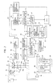
- Fig. 2 is a diagram showing an overall structure of the optical medium reproducing system.
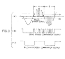
- Fig. 3 is a diagram showing a waveform of a tracking error signal and outputs of comparators.
- Fig. 4 is a circuit diagram of a binarization circuit in the optical medium reproducing system.
- Fig. 5 is a circuit diagram of a pit signal removing circuit in the optical medium reproducing system.
- Fig. 6 is a diagram for use in explaining influences caused by eccentricity of an optical disc.
- Fig. 7 is a diagram for use in explaining a deviation in moving speed of a light beam.
- Fig. 8 is a time chart showing an operation of each portion of a conventional optical disc medium reproducing system.
- Fig. 9 is a time chart showing an operation of each portion of a conventional optical disc reproducing system when a light beam passes an ID portion.
- concentric or helical guide grooves 2, 2 ... are provided with a definite spacing in an optical disc 1 (optical recording medium), and tracks 3 (lands) are formed between the guide grooves 2, 2.
- the tracks 3 are each provided with an ID (identification) portion 4 which is previously recorded by phase pits (pits) and indicating a track number, a sector number and the like (i.e., a portion in which information is recorded in advance by pits).
- ID identification
- pits phase pits
- a track number i.e., a portion in which information is recorded in advance by pits.
- individual pits are not shown, and the overall ID portion 4 is shown by hatched areas for facilitating the description.
- the depth of the pits is set to, for example, ⁇ /4, and the depth of guide grooves 2, 2 is set to, for example, ⁇ /8 ( ⁇ is a wavelength of a light beam 6 which will be described later).
- An indicated arrow 5 denotes one example of traces of the light beam 6 on the optical disc 1 in track access.
- the light beam 6 moves outward in the optical disc 1 between A and B, while the light beam 6 moves inward in the optical disc 1 between B and C.
- this optical disc reproducing system supports the optical disc 1 by a spindle motor 7, and, for example, makes recording/reproduction or erasing of information by an optical head 8 while rotationally driving the optical disc at a constant rotation speed.
- a laser beam emitted from a semiconductor laser 9 is made parallel rays by a collimation lens 10, then passes a beam splitter 11 and is reflected at approximately right angles by a reflecting mirror 12. The reflected rays are converged on the optical disc 1 by a converging lens 13.
- the reflected light from the optical disc 1 reaches the beam splitter 11 via the converging lens 13 and the reflecting mirror 12, it is then reflected at approximately right angles by the beam splitter 11 and is incident on, for example, a bipartite light detector 14.
- the optical head 8 is moved radially on the optical disc 1 by an optical head moving unit such as a linear motor 15.
- the track error signal 19 is input to a binarization circuit 21, so that a binarized track error signal 22 is output (Fig. 1(e)).
- the track error signal requires some correction since this signal is also naturally affected by pits. Actually, however, the track error signal in the pit portion has a shape shown in Fig. 3(A).
- the signal normally has no reverse polarity (for example, a minus side in a part A and a plus side in a part B).
- the track error signal is binarized simply by a zero cross comparator as shown in Fig. 3(B), so as to detect whether the optical head crosses the tracks, it is possible that an erroneous signal is output in the pit portion. It is thus necessary to employ a comparator having hysteresis levels E1 and E2. In this invention, this is realized by employing a binarization circuit 21 shown in Fig. 4. As a result, a binarized signal of clear track crossing shown in Fig. 1(e) can be obtained from the track error signal affected by the pits shown in Fig. 1(b).
- Fig. 4 shows a specific example of the binarization circuit 21.
- the binarization circuit 21 includes comparators 23 and 25 and an RS flipflop 27.
- the track error signal 19 is compared with a predetermined level E1 having a positive value by the comparator 23, so that a binarized signal 24 (Fig. 1(c)) is output.
- the track error signal 19 is also compared with a predetermined level E2 having a negative value by the comparator 25, so that a binarized signal 26 (Fig. 1(d)) is output.
- the above-described binarized signal 24 is input to a set input terminal S of the RS flipflop 27, and the binarized signal 26 is input to a reset input terminal R.
- a binarized track error signal 22 which is not affected by modulation is output form the RS flipflop 27 (see 19a of Fig. 1(b)).
- the binarized track error signal 22 is input to a direction determining circuit 43 at low speed and a rising edge detecting circuit 45 which will be described later.
- a total signal 20 is input to a pit signal generating circuit 28 and a subtractor 32, and a phase pit signal 33 is subtracted from the total signal 20 and then output as a pit removal signal 29 (Fig. 1(h)).
- Fig. 5 shows a specific example of the pit signal generating circuit 28.
- the pit signal generating circuit 28 includes a high pass filter 30 and a clamp circuit 31.
- the high pass filter 30 includes an operational amplifier 34, a capacitor 35 (a capacitance C1) connected to a plus input terminal of the operational amplifier 34, and a resistor 36 (a resistance value R1) connected between the plus input terminal and ground.
- a frequency component of the total signal 20 which corresponds to a change in the amount of light when a light beam crosses phase pits is substantially higher than that corresponding to a change in the amount of light when the light beam crosses tracks. Therefore, selecting the capacitance C1 and the resistance value R1 makes it possible to extract the frequency component corresponding to the phase pits from the input signal of the high pass filter 30.
- This frequency component includes no direct current component.
- the clamp circuit 31 adds a direct current component to the above frequency component.
- the clamp circuit 31 includes a capacitor 37 (a capacitance C2) connected between an output and an input of the clamp circuit 31, a resistor 38 (a resistance value R2) connected between the output and a positive voltage V, and a diode 39 connected between the output and ground.
- the clamp circuit 31 is provided so that its output signal does not rise to a predetermined potential (e.g., a ground potential) or a higher potential when the input signal of the clamp circuit 31 increases. That is, in such a state that the input signal rises to not lower than the ground potential (precisely a forward voltage drop Vdf of the diode 39), a forward current flows through the diode 39, so that an upper end of the output signal does not rise higher than the ground potential.
- the amount of decrease of the input signal passes the capacitor 37, so that the output signal becomes a signal which is lower than the ground potential by the change of the input signal, as shown in the period 33a of Fig. 1(g). Accordingly, a phase pit signal 33 being an output of the clamp circuit 31 becomes a signal representing the changed amount of light corresponding to the phase pits as shown in Fig. 1(g).
- phase pit signal 33 subtracted from the total signal 20 by the subtractor 32, the changed amount of light corresponding to the phase pits in the total signal 20 can be removed, and a pit removal signal 29 which is not affected by the phase pits is obtained. This corresponds to timing at which the light beam 6 crosses the tracks 3.
- the high pass filter 30 is used in the pit signal generating circuit 28, if a time constant C2 ⁇ R2 of the capacitor 37 and the resistor 38 in the clamp circuit 31 is set to be equal to a time constant C1 ⁇ R1 of the high pass filter 30, the pit signal generating circuit 28 carries out almost the same operation as above even without the high pass filter 30.
- the pit removal signal 29 obtained by the pit signal generating circuit 28 and the subtractor 32 is input to a land/groove determining circuit 40, then compared with a predetermined slice level 41 (Fig. 1(h)) by a comparator not shown and output as a land/groove determining signal 42 (Fig. 1(i)).
- a low level of the land/groove determining signal 42 corresponds to the guide grooves 2 (grooves), while a high level thereof corresponds to the tracks 3 (lands).
- the land/groove determining signal 42 and the binarized track error signal 22 are input to the direction determining circuit 43 at low speed.
- the land/groove determining signal 42 is latched at a rising time shown by a circle of Fig. 1(e) of the binarized track error signal 22, whereby a direction signal 44 at low speed (Fig. 1(j)) corresponding to the direction of movement of the light beam 6 is obtained.
- a low level of the direction signal 44 represents that the moving direction of the light beam 6 is from an inner circumference to an outer circumference of the optical disc 1, while its high level represents that the moving direction of the light beam 6 is from the outer circumference to the inner circumference.
- the direction signal 44 at low speed is input to a data selector 51.
- the binarized track error signal 22 is input to the rising edge detecting circuit 45, so that an edge detection signal 46 (Fig. 1(k)) which is to be output for a predetermined period after a rising of the binarized track error signal 22 is output.
- This edge detection signal 46 corresponds to timing at which the light beam 6 crosses over the guide grooves 2 while moving outward in the optical disc 1
- the edge detection signal 46 corresponds to timing at which the light beam 6 crosses over the tracks 3 while moving inward in the optical disc 1.
- the edge detection signal 46 is input to an F/V conversion circuit 47 and an up/down signal generating circuit 54.
- the edge detection signal 46 input to the F/V conversion circuit 47 is F/V (frequency/voltage)-converted. This results in an absolute value of the track crossing rate of the light beam 6, as an output of the F/V conversion circuit 47.
- the output of the F/V conversion circuit 47 is input to a high/low speed determining circuit 48 and compared with a predetermined level. In accordance with a result of the comparison, a signal which determines whether the track crossing rate of the light beam 6 is not lower than a predetermined high speed or lower than a predetermined speed is output from a high/low speed determining circuit 48 and then input into the data selector 51.
- a track crossing rate during a seek (access) operation is about 1m/s at maximum. If a track pitch is 1.6 ⁇ m, then a frequency of a track error signal (and a total signal) is 625kHz. Since a frequency of data recorded by pits is about 2 - 4MHz, this frequency is only about 3 - 6 times a maximum frequency of the track error signal or the total signal.
- a CPU (central processing unit) 50 which receives an instruction of access is able to identify the direction of movement of the optical head 8 by comparing a target track and the present track.
- the optical head 8 is moving at a low speed, however, the light beam 6 sometimes moves in an opposite direction to the direction identified by the CPU50 due to influences by an eccentricity component of the optical disc 1.
- a rotation frequency of the disc fr
- the optical head is moved outward in the disc at a speed v. Since it appears that the track approaches closer and closer to the optical head at the time which the track moves inward in the disc by the rotation of the disc (the time which the moving speed of the track is minus in Fig. 6(B)), a relative moving direction of the optical head and the track is outward similarly to the moving direction of the optical head itself.
- the purpose of the seek (access) operation is not "how many meter point in the radial direction of the disc the optical head moves to", but “which order of track the optical head moves to.”
- a target track is far behind away. Conversely, when the track is coming closer, it is necessary to detect that the target track is close.
- the moving speed of the light beam 6 is higher than the eccentricity speed of the track 3, and hence the movement direction identified by the CPU 50 matches the movement direction of the light beam 6 viewed in a relative positional relationship with the track 3.
- the direction detected by the low-speed-direction determining circuit 43 is adopted as the moving direction of the light beam when the light beam 6 moves at a low speed, and the direction identified by the CPU 50 in accordance with the target track and the present track is adopted when the light beam 6 moves at a high speed, an accurate moving direction of the light beam 6 in access can be detected.
- a signal from the high/low speed determining circuit 48 a low-speed-direction signal 44 and an access direction signal 52 are input in the data selector 51.
- the low-speed-direction signal 44 from the low-speed-direction determining circuit 43 is selected at the time of low speed, while the access direction signal 52 identified by the CPU 50 is selected and output as a direction signal 53 at the time of high speed.
- the edge detection signal 46 and the direction signal 53 are input into the up/down signal generating circuit 54.
- an up signal 55 (Fig. 1 (l)) is generated in response to the edge detection signal 46
- a down signal 56 (Fig. 1 (m)) is generated in response to the edge detection signal 46. It is now assumed that the direction signal 53 is identical to the low-speed-direction signal 44 of Fig. 1 (j).
- the up signal 55 and the down signal 56 are input into the up-down counter 57 and the track crossing speed detecting circuit 58.
- the up signal 55 corresponds to timing at which the light beam 6 crosses over the guide grooves 2 when moving outward in the optical disc 1
- the down signal 56 corresponds to timing at which the light beam 6 crosses over the tracks 3 when moving inward in the optical disc 1.
- the up signal 55 and the down signal 56 are counted by the up-down counter 57, thereby enabling detection of the number of tracks 3 over which the light beam 6 crosses. This detection is made accurately for the foregoing reasons even in a case where the optical disc 1 has eccentricity.
- the up signal 55 and the down signal 56 are input into the track crossing speed detection circuit 58, and F/V conversion means or the like detects the radial moving speed of the light beam 6 with respect to the optical disc 1 in access time (this moving speed is different from the one obtained by the F/V conversion circuit 47 and includes a moving direction).
- the amount of movement of the optical head 8 is detected by the CPU 50 in response to an output of the up-down counter 57.
- a reference speed signal 62 corresponding to a remaining distance to the target track is generated by a reference speed generating circuit 60.
- a moving speed signal 61 output from the track crossing speed detecting circuit 58 and the reference speed signal 62 from the reference speed generating circuit 60 are input to a speed control circuit 63. Based on the difference between the moving speed signal 61 and the reference speed signal 62, a speed control signal 64 is output to a linear motor 15. Accordingly, the speed of the linear motor 15 is controlled so that the moving speed of the optical head 8 is equal to the above reference speed, and the optical head 8 is driven at an optimal speed corresponding to the remaining distance to the target track.
- the moving speed of the light beam 6 is identical to that of the optical head 8. Strictly, the both speeds do not match due to vibration of an actuator spring supporting a lens for focusing the light beam (see Fig. 7). While a method in which a lens is electrically locked so as not to move during a seek operation is widely adapted, the both speeds are set equal in order to facilitate understandings in the present application.
- a definition of "high speed” or “low speed” is such that “low speed” is applied in a case where it is possible that the above-described track eccentricity speed v t is higher than the optical head moving speed v h and the reversal of the relative moving speed and the direction occurs.
- low speed is defined when there is a possibility of (v h - v t ) ⁇ 0 where v t is a track eccentricity speed and v h is an optical head speed.
- the amount of eccentricity of the disc (a displacement in amplitude) is different for industrial use or household use and is several ten to several hundred ⁇ m.
- a rotation frequency of the disc is also in the range from approximately 10Hz for use of CDs to approximately 60Hz for use of computers.
- low speed is determined when the moving speed of the optical head is lower than v m .
- a double or triple value can be revised to v m as a determination reference which can cope with a disc having a slightly larger amount of eccentricity.
- the present invention is effective not only to the ID portion in which information of a sector and a track is recorded by phase pits, but also to a track portion of an ROM disc or an overwrite optical disc of a pit formation type in which data information is recorded by phase pits.
- the optical disc driving apparatus when the optical head 8 moves at a relatively low speed, it is possible to extract only a frequency component provided when the light beam crosses pits by using the high pass filter 30 by utilizing the feature that a frequency component of the total signal 20 which corresponds to a change in the amount of light upon crossing over pits is substantially higher than that which corresponds to a change in the amount of light upon crossing over the tracks 3.
- the frequency component of the total signal 20 which is obtained by the high pass filter 30 and corresponds to the change in the amount of light upon crossing over pits does not include any direct current components, the signal is not allowed to be a signal including information as to a change in the amount of light by pits.
- the clamp circuit 31 clamps a maximum point of the frequency component corresponding to the changed amount of light upon crossing over pits to a definite potential, then the phase pit signal 33 representing the change in the amount of light of the total signal 20 corresponding to pits can be generated. Then, by the subtractor 32 which subtracts the phase pit signal 33 being the signal component corresponding to pits from the total signal 20 and generates the pit removal signal 29, a total signal from which the change in the amount of light by pits is removed is obtained, thereby enabling an accurate detection of the moving direction of the optical head 8 and precisely leading the optical head 8 to a desired track 3.
Landscapes
- Optical Recording Or Reproduction (AREA)
- Moving Of The Head For Recording And Reproducing By Optical Means (AREA)
- Moving Of Head For Track Selection And Changing (AREA)
Claims (7)
- Système de reproduction de support d'enregistrement optique comprenant un appareil et un support d'enregistrement optique (1), ledit appareil comprenant une tête optique (8) pour diriger un faisceau de lumière sur ledit support d'enregistrement optique (1) et recevoir une lumière réfléchie par ledit support d'enregistrement optique (1) de façon à délivrer en sortie un signal de reproduction (20), dans lequeldes plats (3) et des gorges (2) concentriques sont formées de façon alternée dans une direction radiale dudit support d'enregistrement optique (1), et des parties (4) dans lesquelles des informations sont enregistrées à l'avance au moyen de microcuvettes sont présentes sur ledit support d'enregistrement optique, ledit signal de reproduction (20) comprenant un signal ayant une composante de fréquence correspondant auxdites microcuvettes, ladite tête optique (8) balayant la partie (4) constituée par lesdites microcuvettes, caractérisé en ce que ledit appareil comprend:des moyens (28) pour séparer un signal ayant une composante de fréquence correspondant auxdites microcuvettes compris dans ledit signal de reproduction (20);des moyens (31) pour verrouiller sur un niveau prédéterminé une amplitude dudit signal ayant la composante de fréquence; etdes premiers moyens d'élimination (32) pour éliminer dudit signal de reproduction (20) ledit signal séparé verrouillé sur ledit niveau prédéterminé.
- Système de reproduction de support d'enregistrement optique selon la revendication 1, dans lequel la composante de fréquence correspondant auxdites microcuvettes comprend une composante haute fréquence.
- Système de reproduction de support d'enregistrement optique selon la revendication 2, dans lequel lesdits moyens de séparation (28) comprennent un filtre passe-haut (30) et des moyens de verrouillage (31).
- Système de reproduction de support d'enregistrement optique selon la revendication 3, dans lequel
lesdits premiers moyens d'élimination (32) comprennent un soustracteur (32). - Système de reproduction de support d'enregistrement optique selon la revendication 3, dans lequel
ledit appareil comprend un moyen de détection d'erreur de piste (17) servant à détecter une erreur de piste et à générer un signal d'erreur de piste correspondant (19), et des seconds moyens d'élimination (21) pour éliminer une influence exercée par ladite composante haute fréquence dudit signal d'erreur de piste (19). - Système de reproduction de support d'enregistrement optique selon la revendication 5, dans lequel
lesdits seconds moyens d'élimination (21) comprennent des moyens de binarisation (21) pour effectuer la binarisation dudit signal d'erreur de piste (19) à l'aide d'une multiplicité de valeurs de seuil (E1, E2). - Système de reproduction de support d'enregistrement optique selon la revendication 6, dans lequel
lesdits moyens de binarisation (21) comprennent des premiers moyens de comparaison (23) pour déterminer si ledit signal d'erreur de piste (19) est supérieur à un premier potentiel prédéterminé (E1), des seconds moyens de comparaison (25) pour déterminer si ledit signal d'erreur de piste (19) est inférieur à un second potentiel prédéterminé (E2), et une bascule R-S (27) reliée à une sortie (24, 26) desdits premiers et seconds moyens de comparaison (23, 25).
Applications Claiming Priority (2)
| Application Number | Priority Date | Filing Date | Title |
|---|---|---|---|
| JP167195/91 | 1991-07-08 | ||
| JP3167195A JP2710704B2 (ja) | 1991-07-08 | 1991-07-08 | 光記録媒体駆動装置 |
Publications (3)
| Publication Number | Publication Date |
|---|---|
| EP0522499A2 EP0522499A2 (fr) | 1993-01-13 |
| EP0522499A3 EP0522499A3 (en) | 1993-03-31 |
| EP0522499B1 true EP0522499B1 (fr) | 1997-04-23 |
Family
ID=15845192
Family Applications (1)
| Application Number | Title | Priority Date | Filing Date |
|---|---|---|---|
| EP92111490A Expired - Lifetime EP0522499B1 (fr) | 1991-07-08 | 1992-07-07 | Systéme de reproduction d'un milieu d'enregistrement optique avec détection précise de la position de piste |
Country Status (6)
| Country | Link |
|---|---|
| US (1) | US5459705A (fr) |
| EP (1) | EP0522499B1 (fr) |
| JP (1) | JP2710704B2 (fr) |
| KR (1) | KR950014830B1 (fr) |
| CA (1) | CA2073323C (fr) |
| DE (1) | DE69219222T2 (fr) |
Families Citing this family (21)
| Publication number | Priority date | Publication date | Assignee | Title |
|---|---|---|---|---|
| JPH0793077B2 (ja) * | 1987-07-10 | 1995-10-09 | 株式会社日立製作所 | 開閉器用操作装置 |
| JPH07114738A (ja) * | 1993-10-19 | 1995-05-02 | Sharp Corp | マルチビーム記録再生装置 |
| JPH07169064A (ja) * | 1993-12-16 | 1995-07-04 | Sharp Corp | マルチビーム記録再生装置 |
| BR9506787A (pt) * | 1994-02-15 | 1997-09-16 | Philips Electronics Nv | Processos de converter uma série de palavras de informação de m-bit em um sinal modulado e de produzir um suporte de gravação dispositivos codificador decodificador gravador e de leitura sinal e suporte de gravação |
| US5796686A (en) * | 1994-09-01 | 1998-08-18 | Kabushiki Kaisha Toshiba | Track jump control apparatus for disc reproducing system |
| JPH0896379A (ja) * | 1994-09-21 | 1996-04-12 | Nec Corp | 光ヘッドのトラッキング制御装置 |
| US5719836A (en) | 1995-04-07 | 1998-02-17 | Discovision Associates | Optical seeking method and apparatus generating track count signal from tracking error signal and data signal |
| JP3265527B2 (ja) * | 1995-04-27 | 2002-03-11 | 株式会社ニコン | 情報記録媒体 |
| JPH09171625A (ja) * | 1995-12-20 | 1997-06-30 | Nikon Corp | 情報再生装置 |
| KR100280868B1 (ko) * | 1996-05-09 | 2001-02-01 | 윤종용 | 트랙크로스신호 보정장치 |
| JP2845224B2 (ja) * | 1996-11-15 | 1999-01-13 | 日本電気株式会社 | ランド/グルーブ検出装置 |
| JP2865087B2 (ja) * | 1996-11-29 | 1999-03-08 | 日本電気株式会社 | ランドグルーブ位置検出方式及び方法 |
| JP2924841B2 (ja) * | 1997-02-27 | 1999-07-26 | 日本電気株式会社 | 光学情報記録装置および光記録媒体および光記録媒体のトラッキング極性の判別方法 |
| US5914922A (en) * | 1997-12-12 | 1999-06-22 | Cirrus Logic, Inc. | Generating a quadrature seek signal from a discrete-time tracking error signal and a discrete-time RF data signal in an optical storage device |
| TW463151B (en) * | 1999-08-09 | 2001-11-11 | Ind Tech Res Inst | Counting method to dynamically correct the relative track seeking and seeking system of optical storage device thereof |
| US6744711B1 (en) * | 2000-06-20 | 2004-06-01 | Discovision Associates | Method and apparatus for a high-speed search of an optical medium |
| DE10129014A1 (de) * | 2001-06-15 | 2003-01-02 | Infineon Technologies Ag | Verfahren und Vorrichtung zur Risetime-Optimierung eines Signals |
| KR100480627B1 (ko) * | 2002-11-09 | 2005-03-31 | 삼성전자주식회사 | 미러신호를 이용한 스핀들 모터의 등선속도 제어방법 및제어장치 |
| JP5392299B2 (ja) * | 2011-05-31 | 2014-01-22 | 船井電機株式会社 | 光ディスク装置 |
| US9734859B2 (en) | 2013-11-26 | 2017-08-15 | Oracle International Corporation | Quadrature track error signal for optical recording media and devices |
| US10415151B1 (en) * | 2014-03-27 | 2019-09-17 | Varian Semiconductor Equipment Associates, Inc | Apparatus for controlling heat flow within a silicon melt |
Family Cites Families (10)
| Publication number | Priority date | Publication date | Assignee | Title |
|---|---|---|---|---|
| US4959823A (en) * | 1985-07-30 | 1990-09-25 | Laser Magnetic Storage International Company | Tracking and seeking system for use with an optical record carrier having a wobbled track format |
| JPH0799592B2 (ja) * | 1985-10-02 | 1995-10-25 | 松下電器産業株式会社 | 光学式情報記憶担体 |
| JPS62167672A (ja) * | 1986-01-20 | 1987-07-24 | Fujitsu Ltd | デ−タ読取り方式 |
| JP2508477B2 (ja) * | 1987-02-02 | 1996-06-19 | ソニー株式会社 | デイスク装置 |
| US4961182A (en) * | 1987-07-01 | 1990-10-02 | Hitachi, Ltd. | Information retrieving system with level clamping |
| JPH0828073B2 (ja) * | 1987-08-06 | 1996-03-21 | パイオニア株式会社 | ディスクプレ−ヤのトラックジャンプ動作制御装置 |
| JPH01189034A (ja) * | 1987-12-28 | 1989-07-28 | Csk Corp | 光メモリカードのトラッキング装置 |
| JPH01217732A (ja) * | 1988-02-24 | 1989-08-31 | Canon Inc | 光学的情報記録再生装置 |
| JPH02103776A (ja) * | 1988-10-11 | 1990-04-16 | Canon Inc | 信号処理装置 |
| JPH02183422A (ja) * | 1989-01-06 | 1990-07-18 | Toshiba Corp | 情報記録媒体のトラッキング制御装置 |
-
1991
- 1991-07-08 JP JP3167195A patent/JP2710704B2/ja not_active Expired - Fee Related
-
1992
- 1992-07-07 EP EP92111490A patent/EP0522499B1/fr not_active Expired - Lifetime
- 1992-07-07 KR KR1019920012053A patent/KR950014830B1/ko not_active Expired - Lifetime
- 1992-07-07 CA CA002073323A patent/CA2073323C/fr not_active Expired - Fee Related
- 1992-07-07 DE DE69219222T patent/DE69219222T2/de not_active Expired - Lifetime
- 1992-07-08 US US07/910,838 patent/US5459705A/en not_active Expired - Lifetime
Also Published As
| Publication number | Publication date |
|---|---|
| DE69219222D1 (de) | 1997-05-28 |
| US5459705A (en) | 1995-10-17 |
| KR930003044A (ko) | 1993-02-23 |
| JP2710704B2 (ja) | 1998-02-10 |
| EP0522499A3 (en) | 1993-03-31 |
| JPH0512677A (ja) | 1993-01-22 |
| DE69219222T2 (de) | 1997-11-06 |
| CA2073323A1 (fr) | 1993-01-09 |
| CA2073323C (fr) | 1997-04-15 |
| EP0522499A2 (fr) | 1993-01-13 |
| KR950014830B1 (ko) | 1995-12-15 |
Similar Documents
| Publication | Publication Date | Title |
|---|---|---|
| EP0522499B1 (fr) | Systéme de reproduction d'un milieu d'enregistrement optique avec détection précise de la position de piste | |
| GB2312320A (en) | Optical disk with land/groove track | |
| US4701897A (en) | Optical disk apparatus | |
| US6868052B2 (en) | Optical disc playback apparatus and method of judging disc type | |
| JP2633417B2 (ja) | 光記録媒体駆動装置 | |
| JP2598166B2 (ja) | 光ディスク媒体駆動装置 | |
| EP0087973A1 (fr) | Système asservi de poursuite de piste pour appareil de reproduction d'information à disque optique | |
| US6381201B1 (en) | Optical disk apparatus with address polarity determination and confirmation | |
| EP0392775B1 (fr) | Système pour la détection d'erreur de suivi de piste dans un appareil d'enregistrement/reproduction optique | |
| US6188654B1 (en) | Method and apparatus for recording/reproducing by pre-pits detection | |
| JPH0778428A (ja) | ディスク装置のアクセス方向検知回路 | |
| US20040246846A1 (en) | Optical disk drive | |
| EP0736864B1 (fr) | Procédé et appareil de recherche optique de pistes | |
| EP0974958A1 (fr) | Disque optique | |
| JP3652139B2 (ja) | トラッキング制御回路 | |
| KR100698105B1 (ko) | 광 기록매체의 랜드/그루브 트랙 판별 방법 및 장치 | |
| JPH0198169A (ja) | トラック検索装置 | |
| JPH05109093A (ja) | 光学的情報記録再生装置 | |
| JP2000200417A (ja) | 光ディスク装置 | |
| JPH0770069B2 (ja) | 光学式記録再生装置におけるトラツキングサ−ボ回路 | |
| JPH11120623A (ja) | 光ディスク及び光ディスク再生装置 | |
| JPH0215432A (ja) | 光ディスク装置 | |
| KR20020069299A (ko) | 광 디스크 및 신호 검출방법 | |
| JPH02132643A (ja) | 光ディスクドライブ装置 | |
| JPH04228123A (ja) | 情報の記録再生方法および情報記録媒体 |
Legal Events
| Date | Code | Title | Description |
|---|---|---|---|
| PUAI | Public reference made under article 153(3) epc to a published international application that has entered the european phase |
Free format text: ORIGINAL CODE: 0009012 |
|
| AK | Designated contracting states |
Kind code of ref document: A2 Designated state(s): DE FR GB IT NL |
|
| PUAL | Search report despatched |
Free format text: ORIGINAL CODE: 0009013 |
|
| AK | Designated contracting states |
Kind code of ref document: A3 Designated state(s): DE FR GB IT NL |
|
| 17P | Request for examination filed |
Effective date: 19930609 |
|
| 17Q | First examination report despatched |
Effective date: 19950914 |
|
| GRAG | Despatch of communication of intention to grant |
Free format text: ORIGINAL CODE: EPIDOS AGRA |
|
| GRAH | Despatch of communication of intention to grant a patent |
Free format text: ORIGINAL CODE: EPIDOS IGRA |
|
| GRAH | Despatch of communication of intention to grant a patent |
Free format text: ORIGINAL CODE: EPIDOS IGRA |
|
| GRAA | (expected) grant |
Free format text: ORIGINAL CODE: 0009210 |
|
| AK | Designated contracting states |
Kind code of ref document: B1 Designated state(s): DE FR GB IT NL |
|
| ITF | It: translation for a ep patent filed | ||
| REF | Corresponds to: |
Ref document number: 69219222 Country of ref document: DE Date of ref document: 19970528 |
|
| ET | Fr: translation filed | ||
| PLBE | No opposition filed within time limit |
Free format text: ORIGINAL CODE: 0009261 |
|
| STAA | Information on the status of an ep patent application or granted ep patent |
Free format text: STATUS: NO OPPOSITION FILED WITHIN TIME LIMIT |
|
| 26N | No opposition filed | ||
| REG | Reference to a national code |
Ref country code: GB Ref legal event code: IF02 |
|
| PGFP | Annual fee paid to national office [announced via postgrant information from national office to epo] |
Ref country code: NL Payment date: 20020730 Year of fee payment: 11 |
|
| PG25 | Lapsed in a contracting state [announced via postgrant information from national office to epo] |
Ref country code: NL Free format text: LAPSE BECAUSE OF NON-PAYMENT OF DUE FEES Effective date: 20040201 |
|
| NLV4 | Nl: lapsed or anulled due to non-payment of the annual fee |
Effective date: 20040201 |
|
| PG25 | Lapsed in a contracting state [announced via postgrant information from national office to epo] |
Ref country code: IT Free format text: LAPSE BECAUSE OF NON-PAYMENT OF DUE FEES;WARNING: LAPSES OF ITALIAN PATENTS WITH EFFECTIVE DATE BEFORE 2007 MAY HAVE OCCURRED AT ANY TIME BEFORE 2007. THE CORRECT EFFECTIVE DATE MAY BE DIFFERENT FROM THE ONE RECORDED. Effective date: 20050707 |
|
| PGFP | Annual fee paid to national office [announced via postgrant information from national office to epo] |
Ref country code: FR Payment date: 20110727 Year of fee payment: 20 |
|
| PGFP | Annual fee paid to national office [announced via postgrant information from national office to epo] |
Ref country code: GB Payment date: 20110706 Year of fee payment: 20 Ref country code: DE Payment date: 20110629 Year of fee payment: 20 |
|
| REG | Reference to a national code |
Ref country code: DE Ref legal event code: R071 Ref document number: 69219222 Country of ref document: DE |
|
| REG | Reference to a national code |
Ref country code: DE Ref legal event code: R071 Ref document number: 69219222 Country of ref document: DE |
|
| REG | Reference to a national code |
Ref country code: GB Ref legal event code: PE20 Expiry date: 20120706 |
|
| PG25 | Lapsed in a contracting state [announced via postgrant information from national office to epo] |
Ref country code: DE Free format text: LAPSE BECAUSE OF EXPIRATION OF PROTECTION Effective date: 20120710 Ref country code: GB Free format text: LAPSE BECAUSE OF EXPIRATION OF PROTECTION Effective date: 20120706 |