EP0523249A1 - Procede d'inspection magnetique et dispositif prevu a cet effet - Google Patents
Procede d'inspection magnetique et dispositif prevu a cet effet Download PDFInfo
- Publication number
- EP0523249A1 EP0523249A1 EP92904249A EP92904249A EP0523249A1 EP 0523249 A1 EP0523249 A1 EP 0523249A1 EP 92904249 A EP92904249 A EP 92904249A EP 92904249 A EP92904249 A EP 92904249A EP 0523249 A1 EP0523249 A1 EP 0523249A1
- Authority
- EP
- European Patent Office
- Prior art keywords
- magnetic
- distance
- magnetic sensor
- shield
- defect
- Prior art date
- Legal status (The legal status is an assumption and is not a legal conclusion. Google has not performed a legal analysis and makes no representation as to the accuracy of the status listed.)
- Granted
Links
Images









Classifications
-
- G—PHYSICS
- G01—MEASURING; TESTING
- G01N—INVESTIGATING OR ANALYSING MATERIALS BY DETERMINING THEIR CHEMICAL OR PHYSICAL PROPERTIES
- G01N27/00—Investigating or analysing materials by the use of electric, electrochemical, or magnetic means
- G01N27/72—Investigating or analysing materials by the use of electric, electrochemical, or magnetic means by investigating magnetic variables
- G01N27/82—Investigating or analysing materials by the use of electric, electrochemical, or magnetic means by investigating magnetic variables for investigating the presence of flaws
Definitions
- the present invention relates to a magnetic inspection method and a magnetic inspection apparatus wherein a magnetic field is generated by a magnetizer in a to-be-inspected object formed of a magnetic material such as steel plate and a leakage magnetic flux due to a defect on the object is detected by a magnetic sensor.
- a magnetic inspection apparatus detects, by utilizing magnetism, defects such as internal and surface flaws and inclusion in a thin steel strip or a to-be-inspected object. It was reported that a magnetic inspection apparatus, in which a magnetic sensor array comprising linearly arranged magnetic sensors for detecting magnetic fluxes is built, is capable of successively detecting defects on a running thin steel strip over the entire width thereof (Published Unexamined Japanese Utility Model Application (PUJUMA No. 63-107849).
- Figs. 39 and 40 are schematic cross-sectional views showing, in different directions, the above-mentioned magnetic inspection apparatus for successively detecting the defects on the running thin steel strip.
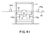
- Fig. 41 is a side view showing the state in which the magnetic inspection apparatus is built in a support apparatus.
- a horizontal arm 12 is supported by a pair of spring members 13a and 13b within a frame 11 set on the floor of a room. Accordingly, the arm 12 is vertically movable.
- a stationary shaft 2 of the magnetic inspection apparatus is fixed at the center of the arm 12.
- a pair of guide rolls 14a and 14b for guiding a thin steel strip 10 on the outer peripheral surface of a hollow roll 1 are arranged on both sides of the frame 11.
- one end portion of the stationary shaft 2 penetrates the hollow roll 1 of a non-magnetic material along the center axis of the roll 1.
- the other end portion of the shaft 2 is fixed on the horizontal arm 12.
- the stationary shaft 2 is supported on the inner peripheral surfaces of both end portions of the hollow roll 1 by a pair of rolling bearings 3a and 3b such that the shaft 2 is situated along the center axis of the hollow roll 1. Accordingly, the hollow roll 1 is freely rotatable about the stationary shaft 2.
- a magnetizing core 4c having a substantially U-cross section is fixed to the stationary shaft 2 by means of a support member 5 within the hollow roll 1, such that magnetic poles 4a and 4b of the core 4c are situated close to the inner peripheral surface of the hollow roll 1.
- a magnetizing coil 6 is wound around the magnetizing core 4c.
- the magnetizing core 4c and magnetizing coil 6 constitute a magnetizer 4.
- a magnetic sensor array 7 consisting of magnetic sensors 7a arranged linearly along the axis of the hollow roll 1 is fixed to the stationary shaft 2 between the magnetic poles 4a and 4b of the magnetizing core 4c.
- a power cable 8 for supplying an excitation current to the magnetizing coil 6 and a signal cable 9 for taking out output signals from the magnetic sensors 7a of the magnetic sensor array 7 are led to the outside through the inside passage of the stationary shaft 2. Accordingly, the positions of the magnetizer 4 and magnetic sensor array 7 are fixed, and the hollow roll 1 rotates around the magnetizer 4 and magnetic sensor array 7 with a small gap.
- the hollow roll 1 of the magnetic inspection apparatus with the above structure When the outer peripheral surface of the hollow roll 1 of the magnetic inspection apparatus with the above structure is pressed on one side surface of the thin steel strip 10 under a predetermined pressure which runs, for example, in a direction a , the hollow roll 1 rotates in a direction b since the stationary shaft 2 is fixed on the horizontal arm 12.
- the level of this output detection signal corresponds to the magnitude of the internal or surface defect of the thin steel strip 10.
- the S/N does not basically increase unless the magnetic force is adequate.
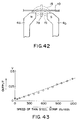
- Fig. 42 when the magnetic poles 4a and 4b are situated near the thin steel strip 10, magnetic force lines extend from the pole 4a to the pole 4b through a magnetic gap, the thin steel plate 10 and another magnetic gap. Since the thin steel strip 10 is formed of a ferromagnetic material, magnetic fluxes do not leak out of the thin steel strip 10 while passing through the strip 10 if no defect is present in the strip 10.
- the strip 10 is magnetically saturated, as shown in Fig. 42.
- a large floating magnetic flux 15 occurs even in a defect-free portion.
- the actual value of the floating flux 15 is extremely high, e.g. several Gauss to several-ten Gauss.
- Fig. 43 shows the relationship between the output voltage and the speed of the thin steel strip 10, in the case where the vertical floating magnetic flux in the defect-free portion was measured with the sensitivity of the magnetic sensors 7a lowered intentionally. As shown in Fig. 43, the output voltage rises as the speed of the thin steel strip 10 increases. Accordingly, the variation in vertical component of the floating magnetic flux 15 rises in accordance with the increase in speed.
- each magnetic sensor 7a detects the floating flux and leakage magnetic flux simultaneously, as shown in Fig. 42.
- a first object of the invention is to provide a magnetic inspection method and apparatus capable of remarkably decreasing a floating magnetic flux intersecting a magnetic sensor for detecting a leakage magnetic flux due to a defect, and capable of preventing saturation of output of the magnetic sensor, exactly detecting a small defect, and enhancing inspection accuracy greatly.
- a second object of the invention is to provide an optimal shield shape for a magnetic sensor, thus attaining a high S/N in an output signal from the magnetic sensor.
- a third object of the invention is to provide a magnetic inspection apparatus capable of eliminating a noise component contained in an output signal from a magnetic sensor, which is due to a local variation in magnetic permeability of an object to be inspected, thereby remarkably enhancing the inspection accuracy of the defect.
- a magnetic sensor for detecting a leakage magnetic flux due to an internal or surface defect of the to-be-inspected object is provided at a substantially middle point of a line connecting a pair of magnetic poles of a magnetizer for generating a magnetic field in the object or a line parallel to this connecting line.
- a shield body with a low coercive force is provided on each of sides of the magnetic sensor, which face the magnetic poles of the magnetizer.
- magnetic poles 41a and 41b of a magnetizer faces a to-be-inspected object 42 formed of, e.g. a thin steel strip.
- a magnetic sensor 71a is provided at the center of a line parallel to a line connecting the magnetic poles 41a and 41b.
- a first shield body 43a is situated on one side of the magnetic sensor 71a, which faces the magnetic pole 41a.
- a second shield body 43b is situated on the other side of the magnetic sensor 71a, which faces the other magnetic pole 41b.
- the shield bodies with low coercive force are provided on both sides of the magnetic sensor 71a, the floating magnetic flux crossing the magnetic sensor 71a is remarkably reduced.
- the magnetic sensor 71a faces the object 42.
- the sensor 71a detects a leakage magnetic flux corresponding to the defect.
- the ambient floating magnetic flux 15a is small, the magnetic sensor is not saturated and only the leakage magnetic flux can efficiently be detected.
- a magnetic field 45 generated around the defect 44 exhibits a magnetic flux distribution characteristic of a very small magnetic pole, as shown in the figure.
- the magnetic sensor 71a detects a magnetic flux distributed vertically, as indicated by a solid line 46.
- the width Wh of the magnetic field 45 due to the defect 44 is only several mm. Even if the shield bodies 43a and 43b are provided, the magnetic field 45 can be put between the shield bodies 43a and 43b. Thus, the magnetic sensor 71a can detect the leakage magnetic flux of the magnetic field 45 due to the defect 44, without being influenced by the shield bodies 43a and 43b. That is, the defect 44 can be detected with a high S/N.
- the distance between the shield bodies is set to be 2.2 times or more, and 2.8 times or less, the distance between the magnetic sensor and the object.
- each shield body has an L-cross section composed of a vertical portion and a horizontal portion, and the width of the horizontal portion in the direction of arrangement of the magnetic poles is 0.4 time or more, and 0.6 time or less, the distance between the magnetic poles.
- the ratio of a component of the floating magnetic flux in a defect-free portion, which is not shielded by the shield body and reaches the magnetic sensor increases. If the distance A between the magnetic sensor and the shield body is decreased, the ratio of the component of the floating magnetic flux, which reaches the magnetic sensor, decreases. However, if the distance A becomes too small, the leakage magnetic flux due to the defect does not easily reach the magnetic sensor. On the other hand, the ratio of the component of the magnetic flux, which reaches the magnetic sensor, depends largely on the lift-off L represented by the distance between the magnetic sensor and the object.
- the relationship between the distance 2A between the shield bodies and the lift-off L is defined by 2.2 ⁇ 2A/L ⁇ 2.8 (1)
- the ratio of the leakage magnetic flux to the floating magnetic flux in the magnetic flux crossing the magnetic sensor can be increased, and the leakage magnetic flux can efficiently be detected.
- the value of formula (1) was calculated on the basis of the result of a computer simulation conducted on the magnetic field at the position of the magnetic sensor, by making and using a test model.
- the floating magnetic flux and leakage magnetic flux reaching the magnetic sensor are attenuated by the presence of the shield bodies. If the ratio (W/B) of the width W of each shield body to the inter-magnetic pole distance B is varied, the attenuation amount varies. The attenuation amount differs between the floating magnetic flux and the leakage magnetic flux. Accordingly, a range in which the attenuation amount of the floating magnetic flux is large and the attenuation amount of the leakage magnetic flux is small is found.
- the ratio (W/B) is defined by 0.4 ⁇ W/B ⁇ 0.6 (2) Thereby, the ratio of the leakage magnetic flux to the floating magnetic flux in the magnetic flux crossing the magnetic sensor can be increased, and the leakage magnetic flux can efficiently be detected.
- a plurality of magnetic sensors are arranged at regular intervals in the width direction of the running object.
- a difference signal between output signals from those ones of said magnetic sensors which are separated by a predetermined distance is calculated by a corresponding subtraction circuit.
- An absolute value of each difference signal output from each subtraction circuit is calculated by a corresponding absolute value circuit.
- An arithmetic operation circuit evaluates the defect of the object on the basis of the output signal from each absolute value circuit.
- an area of non-uniformity of magnetic permeability is much greater than an area of a defect.
- the variation component of the leakage magnetic flux due to non-uniform magnetic permeability is detected simultaneously by a number of adjacent magnetic sensors.
- the leakage magnetic flux due to the defect is detected by a small number of magnetic sensors, e.g. on or two sensors.
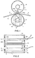
- Figs. 1, 2 and 3 are cross-sectional views showing a magnetic inspection apparatus according to the embodiment which is incorporated in an inspection line in a factory.
- the same parts as in the conventional magnetic inspection apparatus shown in Figs. 39, 40 and 41 are denoted by like reference numerals. Thus, detailed descriptions of the common parts are omitted.
- a thin steel strip 10 or an object to be inspected is interposed between upper and lower hollow rolls 1 and 1a.
- two horizontal arms 12 and 12a are supported within a frame 11 by means of spring members 13a, 13b, 13c and 13d.
- the horizontal arms 12 and 12a are vertically movable.
- Stationary shafts 2 and 2a of the magnetic inspection apparatus are fixed at middle parts of the horizontal arms 12 and 12a.
- a pair of guide rolls 14a and 14b for guiding the thin steel strip 10 between the hollow rolls 1 and 1a of the magnetic inspection apparatus are provided on both sides of the frame 11.
- an end portion of the stationary shaft 2 penetrates a center shaft of the lower hollow roll 1 made of a non-magnetic material.
- the stationary shaft 2 is rotatably supported by a pair of rolling bearings 3a and 3b such that the shaft 2 is situated along the center axis of the hollow roll 1.
- the hollow roll 1 is freely rotatable about the stationary shaft 2.
- a magnetizing core 4c around which a magnetizing coil 6 of a magnetizer 4 is wound is fixed to the stationary shaft 2 via a support member 5, such that magnetic poles 4a and 4b are situated close to the inner peripheral surface of the hollow roll 1.
- the upper hollow roll 1a which is provide above the lower hollow roll 1 with the thin steel strip 10 interposed, is rotatable about a stationary shaft 2a.
- the roll 1a rotates in the direction c .
- a magnetic sensor array 7 is fixed to the stationary shaft 2a of the hollow roll 1a via a support rod 21a so as to face the magnetic poles 4a and 4b of the magnetizer 4 housed in the lower hollow roll 1.
- the magnetic sensor array 7 comprises magnetic sensors 7a arranged linearly in the width direction of the thin steel strip 10. Signal cables of the magnetic sensors 7a are led out through the stationary shaft 2a.
- One shield plate 22a is situated on one side of the magnetic sensor array 7 so as to face the magnetic pole 4a.
- the other shield plate 22b is situated on the other side of the sensor array 7 so as to face the magnetic pole 4b.
- the shield plates 22a and 22b are made of a material having high magnetic permeability and low coercive force.
- the shield plates 22a and 22b are made of Permalloy.
- the shield plates 22a and 22b are fixed to the center shaft 2a by means of support members (not shown).
- Fig. 4 is an enlarged view of an important portion.
- Each magnetic sensor 7a of the magnetic sensor array 7 is a saturable-type magnetic sensor formed by winding a detection coil around a rod-shaped core of ferromagnetic material.
- the height H of each shield plate 22a, 22b is greater than the length D of the rod-shaped core of each magnetic sensor 7a.
- the lower ends of the shield plates are substantially on a level with the lower end of each magnetic sensor 7a. It suffices if the height H is at least 1/2 of the length D of the rod-shaped core.
- each magnetic sensor 7a is 5 mm.
- the height H of each shield plate 22a, 22b is 16 mm, and the thickness of each shield plate is 0.2 mm.
- a lift-off or a distance between each magnetic sensor 7a and each shield plate 22a, 22b, on the one hand, and the thin steel strip 10, on the other, is 3.6 mm.
- the length of each shield plate 22a, 22b in the width direction of the thin steel strip 10 is greater than the width (length) of the magnetic sensor array 7.
- the hollow rolls 1 and 1a rotate in the directions b and c .
- an excitation current is supplied to the magnetizing coil 6 and a closed magnetic path is formed by the running thin steel strip 10 and the magnetic poles 4a and 4b of the magnetizing core 4c stored in the lower hollow roll 1.
- a leakage magnetic flux occurs.
- the leakage magnetic flux is detected by the magnetic sensor 7a of the sensor array 7 housed in the upper hollow roll 1a, which magnetic sensor 7a corresponds to the position of the defect. This magnetic sensor 7a outputs a detection signal.
- the gravitational force of the thin steel strip 10 is not directly exerted on the upper hollow roll 1a.
- the thickness of the upper hollow roll 1a is made less than that of the lower hollow roll 1. Accordingly, the distance between the magnetic sensor array 7 and the thin steel strip 10 can be decreased, and the detection sensitivity of the sensor array 7 can be enhanced.
- Figs. 7 and 8 are graphs showing computer simulation results, indicating floating magnetic flux distributions obtained before and after the shield plates 22a and 22b as shown in Fig. 4 are provided.
- the original point P is an intersection between the upper surface of the thin steel strip 10 (in Fig. 4) and the center line between the magnetic poles 4a and 4b.
- Solid lines indicate magnetic force lines produced between the magnetic poles 4a and 4b.
- the values a to f stated on the right side of each graph indicate vertical components of magnetic field (floating magnetic field) at the corresponding locations. Accordingly, the (-) signs indicate downward magnetic field.
- Fig. 7 shows the case where the shield plate 22b is not provided
- Fig. 8 shows the case where the shield plate 22b is provided.
- the shield plate 22b when the shield plate 22b is provided, it is understood that the vertical component of the floating magnetic flux intersecting at the respective locations of the magnetic sensor 7a is remarkably reduced.
- Fig. 9 shows the case where a shield plate 23 having an L-cross section was used as a shield body.
- the shield plate 23 comprises a vertical portion 24a having the same shape as the shield plate 22b shown in Fig. 4, and a horizontal portion 24b extending outwardly from the lower end of the vertical portion 24a.
- the horizontal width W of the horizontal portion 24b is 2 mm.
- Fig. 10A shows an output waveform of each magnetic sensor 7a before the shield plates are not provided
- Fig. 10B shows an output waveform of each magnetic sensor 7a after the shield plates 22a and 22b shown in Fig. 4 are provided.
- the sensitivity of the magnetic sensor 7a at the time the waveform of Fig. 10B was observed is set to be higher that the sensitivity at the time the waveform of Fig. 10A was observed.
- Fig. 11 shows actual measurement data on the intensity of the floating magnetic flux detected by each magnetic sensor 7a in the case where the defect-free thin steel strip 10 was inspected by the apparatus of the embodiment. The measurement was conducted under the conditions that no shield plate was provided, the shield plates 22a and 22b shown in Fig. 4 were provided, and the shield plate 23 having the L-cross section was provided.
- the shield plates As shown in the figure, by providing the shield plates, it is understood that the output voltage due to floating magnetic flux detected by each magnetic sensor 7a is remarkably decreased. As stated above, the leakage magnetic flux due to the defect is hardly influenced by the presence of the shield plate. As a result, the ratio of the leakage magnetic flux due to the defect to the floating magnetic flux increases, and the defect detection S/N increases.
- Fig. 12 is a graph showing the output ratio (Vs/Vi) between the output voltage Vi due to the floating magnetic flux of the defect-free portion and the output voltage Vs obtained by compounding the leakage voltage due to a defect in the case where the defect exists and the output voltage Vi due to the floating magnetic flux.
- the output ratio (Vs/Vi) was experimentally obtained under the aforementioned measurement conditions.
- the output voltage is not saturated, the output voltage corresponding to the magnitude of the defect is obtained.
- a small defect in the thin steel strip 10 can be detected with high precision.
- the distance 2A between the shield plates 22a and 22b is set to be too small, not only the floating magnetic flux but also the leakage magnetic flux due to the defect in the thin steel strip 10 is shielded. As a result, the S/N of the output signal of the magnetic sensor 7a is lowered, to the contrary. Inversely, if the distance 2A between the shield plates 22a and 22b is too large, the floating magnetic flux is shielded. Thus, an optimal value should be present with respect to the distance 2A.
- the distance B between magnetic poles 34a and 34b is variable between 10 mm, 20 mm and 30 mm.
- the vertical component of the magnetic density detected by the magnetic sensor 7a situated at the center between the magnetic poles was calculated by the aforementioned computer simulation in the case where the distance 2A between the shields was variously changed.
- the defect is present at the center of the thin steel strip 10.
- S indicates the differential magnetic flux density between the leakage magnetic flux due to the defect and the floating magnetic flux of the defect-free portion of the thin steel strip 10
- N indicates the variation in floating magnetic flux density of the entire thin steel strip in the case where the magnetic sensor 7a oscillates in the X-direction by ⁇ 0.2 mm with respect to the point P as a central point. That is, N is noise due to the leakage magnetic flux which occurs when the magnetic sensor 7a oscillates owing to the thin steel strip 10 running on the rolls and by the rolls.
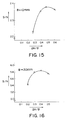
- Fig. 15 is a characteristic graph showing the variation in the S/N of the vertical component at point P in the case where the distance 2A between the shield plates is varied in the state in which the inter-magnetic pole distance B of the magnetizer 34 is set at 10 mm.
- the horizontal axis is set at the value (2A/B) obtained by normalizing the inter-shield plate distance 2A by the inter-magnetic pole distance B.
- the S/N takes a maximal value when the inter-shield plate distance 2A normalized by the distance B is about 0.5.
- Fig. 16 is a characteristic graph showing the variation in the S/N in the case where the distance B is 20 mm. In the case where the inter-magnetic pole distance B is 20 mm, the S/N takes a maximal value when the inter-shield plate distance (2A/B) is about 0.4.
- Fig. 17 is a characteristic graph showing the variation in the S/N in the case where the inter-magnetic pole distance B is 30 mm. In the case where the distance B is 30 mm, the S/N takes a maximal value when the inter-shield plate distance (2A/B) is about 0.3.
- FIG. 18 is a graph showing the relationship between the inter-magnetic pole distance B and the inter-shield plate distance 2A at which the maximal S/N is obtained when the distance B is 10 mm, 20 mm and 30 mm, i.e. the optimal inter-shield plate distance [2A]b.
- the inter-shield plate distance [2A] is set to meet equation (3) in relation to the inter-magnetic pole distance B, the optimal S/N is obtained.
- the distance [2A] meets formula (4), a practically sufficiently high S/N is obtained: -0.01B + 0.55 ⁇ 2A ⁇ -0.01B + 0.65 (4)
- the shape of the shield body provided on that side of the magnetic sensor 7a which faces the magnetic pole 4a, 4b will now be considered.
- Possible shapes of the shield body are a pair of shield plates 22a, 22b shown in Fig. 13, shield plate 23 having the L-cross section shown in Fig. 9, and a shield body 25 having a U-cross section as shown in Fig. 14.
- the shield body 25 can magnetically shield not only the sides of the magnetic sensor 7a but also that face of the sensor 7a which is not opposed to the thin steel strip 10. Accordingly, a floating magnetic flux parallel to the thin steel strip 10 enters one of the vertical portions of the magnetic shield body 25, passing through an intermediate horizontal portion and goes out of the other vertical portion. As a result, it becomes difficult for the floating magnetic flux to enter the inside of the shield body 25 having the U-cross section.
- the S/N of the output signal of the magnetic sensor 7a is further enhanced.
- the distance between the vertical portions of the shield body 25 is 2A, like the distance between the shield plates 22a and 22b shown in Fig. 13.
- the relationship between the optimal distance [2A]b and the inter-magnetic pole distance B for obtaining the optimal S/N was examined by the same method as with the shield plates 22a and 22b shown in Fig. 13.
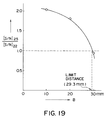
- [S/N]22 of the optimal shield distance [2A]b of the shield plates 22a and 22b shown in Fig. 13 was obtained with respect to each inter-magnetic pole distance B.
- Fig. 19 is a graph showing the calculation result. As can be seen from the characteristic graph of Fig. 19, when the inter-magnetic pole distance B is less than a limit distance of 29.3 mm, a higher S/N is obtained with the shield body 25 having the U-cross section shown in Fig. 14. Inversely, when the distance B exceeds 29.3 mm, a higher S/N is obtained with the shield plates 22a and 22b arranged in parallel as shown in Fig. 13.
- the floating magnetic flux parallel to the thin steel strip 10 is greatly attenuated while passing through the horizontal portion of the shield body 25 with the U-cross section.
- the magnetic flux extending normally towards the thin steel plate 10 is biased to the shield body 25. Consequently, the floating magnetic flux of the sensor unit increases, and the S/N decreases.
- the limit distance 29.3 mm is definitely determined when the width 2A of the shield plates 22a and 22b, or shield body 25, in the direction of arrangement of the magnetic poles and the inter-magnetic pole distance B meet the condition of equation (3).
- Fig. 20 is a cross-sectional side view showing an important portion of a magnetic inspection apparatus according to another embodiment of the present invention
- Fig. 21 is a front view of the important portion of this apparatus.
- the same parts as in the embodiment of Fig. 1 are denoted by like reference numerals. Thus, detailed descriptions of the common parts are omitted.
- the magnetic sensor array 7 arranged along the center axis between the magnetic poles 4a and 4b housed within the hollow roll 1 and the shield plates 22a and 22b provided on both sides of the magnetic sensor array 7 are attached to a support frame 51 situated along the axis of the hollow roll 1.
- the support frame 51 is supported on the upper surface of the thin steel strip 10 by means of a number of rollers 52 and 53 arranged in two lines along the axis of the hollow roll 1 via support arms 54 and 55.
- the lift-off L (or the distance) between the magnetic sensors 7a of the magnetic sensor array 7 and the surface of the thin steel strip 10 is kept at a constant value determined by the outside diameter of each roller 52, 53 and the shape of the support frame 51.
- the horizontal movement of the support frame 51 is restricted by a support mechanism (not shown) so as to keep a predetermined relationship between the magnetic sensors 7a and the magnetic poles 4a and 4b.
- each roller 52, 53 is much smaller than that of the hollow roll 1a shown in Fig. 1.
- the moment of inertia of each roller 52, 53 is much smaller than that of the hollow roll 1a shown in Fig. 1. Therefore, it is not necessary to increase the strength of the support frame 51 and rollers 52 and 53 in particular.
- the maintenance of the magnetic sensor array 7 is easier than in the case where the array 7 is housed within the hollow roll 1a.
- Fig. 22A is a cross-sectional front view showing an important portion of a magnetic inspection apparatus according to still another embodiment of the present invention, and Fig. 22B shows an external appearance of this apparatus.
- the same parts as in the embodiment of Fig. 1 are denoted by like reference numerals, and detailed descriptions of the common parts are omitted.
- a pair of rollers 59 and 60 of, e.g. rubber are attached via shafts 57 and 58 on both sides of a support frame 56 storing the magnetic sensor array 7 facing the thin steel strip 10 and the shield plates provided on both sides of the array 7.
- the rubber rollers 59 and 60 are put in contact with outer peripheral edge portions of the hollow roll 1.
- the lift-off L (or the distance) between the magnetic sensor array 7 and the surface of the thin steel strip 10 is kept at a constant value determined by the outside diameter of each roller 59, 60 and the shape of the support frame 51. Accordingly, the magnetic sensor array 7 is not influenced by vibration due to running of the thin steel strip 10.
- the horizontal movement of the support frame 56 is restricted by a support mechanism (not shown) so as to keep a predetermined relationship between the magnetic sensor array 7 and the magnetic poles 4a and 4b.
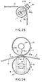
- Fig. 23 is a cross-sectional side view showing an important portion of a magnetic inspection apparatus according to still another embodiment of the present invention.
- the same parts as in the embodiment of Fig. 1 are denoted by like reference numerals, and detailed descriptions of the common parts are omitted.
- the thin steel strip 10 is wound around the hollow roll 1 storing the magnetizer 4 over about 90° with a predetermined tensile force applied.
- a support frame 61 storing the magnetic sensor array 7 and shield plates 22a and 22b is situated outside the hollow roll 1 so as to face the magnetic poles 4a and 4b of the magnetizer 4.
- the angle of contact of the thin steel strip 10 with the hollow roll 1 is very large, i.e. 90°.
- vibration of the thin steel strip 10 is remarkably damped while the steel strip 10 is being in contact with the hollow roll 1. Therefore, the lift-off L between the magnetic sensor array 7 and steel plate 10 can be decreased, and the magnetic inspection sensitivity and S/N can be enhanced.
- Fig. 24 is a cross-sectional view schematically showing the structure of the magnetic inspection apparatus according to still another embodiment of the invention.
- the same parts as in the embodiment of Fig. 1 are denoted by like reference numerals, and detailed description of the common parts is omitted.
- shield plates 23a and 23b each having an L-cross section are supported by support members (not shown) on both sides of the magnetic sensor 7a in the upper hollow roll 1a, which are opposed to the magnetic poles 4a and 4b.
- Each of the shield plates 23a and 23b has the same shape as the shield plate 23 shown in Fig. 9.
- each of the shield plates 23a and 23b has a vertical portion 24a with a height H in a direction perpendicular to the thin steel strip 10, and a horizontal portion 24b with a width W in a direction parallel to the steel strip 10.
- Each shield plate 23a, 23b has a thickness t .
- Each shield plate 23a, 23b is situated at a distance A from the magnetic sensor array 7. The lower ends of the shield plates 23a and 23b are substantially on a level with the lower end of each magnetic sensor 7a.
- each magnetic sensor 7a is 5 mm
- the height H of each shield body 23a, 23b is 16 mm
- the thickness of each shield body is 0.2 mm.
- the width W of the horizontal portion 24b is 6 mm.
- the distance A between each shield body 23a, 23b and the center axis of each magnetic sensor 7a is 4 mm.
- the lift-off L represented by the distance between the thin steel strip 10, on one hand, and each magnetic sensor 7a and each shield body 23a, 23b, on the other hand, is 3.6 mm.
- the length of each shield plate 23a, 23b in the axial direction of the hollow roll 1 is greater than that of the magnetic sensor array 7. Further, the inter-magnetic pole distance B of the magnetizer 4 is 15 mm.
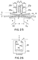
- a test model of the magnetizer 34 with the shape as shown in Fig. 26.
- the distance B between the magnetic poles 34a and 34b is variable between 10 mm, 20 mm and 30 mm.
- the thickness of each steel plate forming a magnetizing core 34c is 0.4 mm.
- the current density of a current flowing in a magnetizing coil 36 is 1.25 ⁇ 105 A/m2 is 3 mm.
- a center point O of the thin steel strip 10 or the object to be inspected is the original point of (X, Y) coordinates.
- the shield plates 22a and 22b having only vertical portions without horizontal portions, as shown in Fig. 27, and the shield plates 23a and 23b having both vertical portions 24a and horizontal portions 24b, as shown in Fig. 28, are located in the (X, Y) coordinates.
- the length D of the magnetic sensor 7a provided between the shield plates 22a and 22b (23a and 23b) is 5 mm.
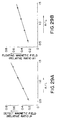
- Fig. 29A shows a ratio ⁇ between a magnetic field (vertical component) ⁇ 1 in the case where the shield plates 23a and 23b are provided and a magnetic field (vertical component) ⁇ 2 in the case where the shield plates 22a and 22b are not provided, under the condition that the sample with the standard defect is used.
- the horizontal axis of Fig. 29A indicates (A/L). That is, Fig. 29A shows the relative ratio ⁇ of the defect magnetic field, depending on the presence/absence of the shield.
- Fig. 29B shows a ratio ⁇ between a magnetic field (vertical component) ⁇ 1 in the case where the shield plates 22a and 22b are provided and a magnetic field (vertical component) ⁇ 2 in the case where the shield plates 22a and 22b are not provided, under the condition that the defect-free sample is used.
- the horizontal axis of Fig. 29B indicates (A/L). That is, Fig. 29B shows the relative ratio ⁇ of the defect magnetic field, depending on the presence/absence of the shield.
- the relative ratio R1 in the state in which the shield plates 22a and 22b are not provided is set at 1.
- Fig. 30 shows the ratio R1 between the magnetic field ( ⁇ ), in which the leakage magnetic flux due to the defect and the floating magnetic flux are added, and the magnetic field ( ⁇ ) of only the floating magnetic flux.
- the higher the relative ratio R1 the higher the ratio of the leakage magnetic field due to the defect included in the magnetic field detected by the magnetic sensor 7a.
- the optimal range of the ratio (A/L) of the half distance A of the distance 2A between the shield plates 22a and 22b to the lift-off L is 1.1 to 1.4 expressed by formula (1).
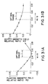
- the horizontal axis of Fig. 31A indicates (W/B). That is, Fig. 31A shows a relative ratio R2 of the floating magnetic flux, depending on the presence/absence of the shield.
- the direction of the vertical component of the magnetic field intersecting the magnetic sensor 7a may changed to an upward direction or a downward direction, depending on the presence/absence of the shield plates 23a and 23b.
- the calculated value may be a (-) value.
- the region of the (-) value is evaluated by an absolute value.
- the horizontal axis of Fig. 31B indicates (W/B). Accordingly, Fig. 31B shows the relative value R3 of the magnetic field including the floating magnetic flux and the leakage magnetic flux due to the defect, depending on the presence/absence of the shield.
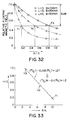
- Fig. 32 shows the simulation result of the vertical component of the magnetic field detected by the magnetic sensor 7a in the case where the defect-free sample was used and the ratio (H/D) of the height H of the magnetic shield 22a, 22b to the length D of the magnetic sensor 7a was varied.
- the lift-off L and inter-magnetic pole distance B were used as parameters.
- Fig. 32 when the height H of the shield plate 22a, 22b is increased, the floating magnetic field detected by the magnetic sensor 7a decreases.
- values of the ratio (H/D) at locations where the characteristic lines intersect the -6 dB line are Y1, Y2 and Y3.
- Y1, Y2 and Y3 can be approximated by the characteristic of Fig. 33, when the horizontal axis indicates the ratio (B/L).
- the shield plates 22a to 23b are provided on both sides of the magnetic sensor 7a and the relationship between the width of each shield plate, height H of each shield plate, distance 2A between the shield plates, inter-magnetic pole distance B of the magnetizer, lift-off L, and height D of the magnetic sensor 7a is determined by formulae (1), (2) and (3).
- the floating magnetic flux component in the magnetic field detected by the magnetic sensor 7a can be decreased, and only the leakage magnetic flux component due to the defect can be remarkably increased.
- saturation of the output of the magnetic sensor 7a can be prevented, the defect detection sensitivity increased, and the detection precision enhanced.
- the present invention is not limited to the above embodiments.
- the magnetic sensor array 7 is provided within the upper hollow roll 1a.
- the shield plates 22a and 22b may be provided on both sides of the magnetic sensor array 7 within the hollow roll 1 of the conventional apparatus shown in Fig. 39.
- the shield plates 22a and 22b or L-cross sectional shield plates 23a and 23b are provided on both sides of the magnetic sensor array 7.
- a cylindrical shield body surrounding the entire magnetic sensor array 7 may be provided.
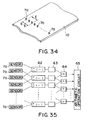
- Fig. 34 shows schematically an important portion of a magnetic inspection apparatus according to another embodiment of the present invention.
- This apparatus has the same structure as shown in Figs. 1, 2 and 3.
- a number of magnetic sensors 7a are arranged within the upper hollow roll 1, as shown in Fig. 34, at regular intervals S in the width direction of the thin steel strip 10.
- Fig. 35 is a block diagram showing an electric structure of the apparatus of this embodiment.
- Outputs from the magnetic sensors 7a are input to subtraction circuits 62.
- Each subtraction circuit 62 receives a pair of output signals from a pair of magnetic sensors with another magnetic sensor interposed therebetween, arranged in the width direction of the thin steel strip 10.
- the subtraction circuit 62 subtracts one output signal from the other output signal and outputs a difference signal.
- Difference signals from the subtraction circuits 62 are input to absolute value circuits 63.
- the absolute value circuits 63 calculate absolute values of the input difference signals and output absolute value signals.
- the absolute value signals output from the absolute value circuits 63 are input to summing circuits 64.
- Each summing circuit 64 sums absolute value signals from adjacent two absolute value circuits 63 and delivers a sum signal to an arithmetic operation circuit 65.
- the arithmetic operation circuit 65 calculates the defect position in the width direction of the thin steel strip 10 and defect magnitude on the basis of the signal level of each sum signal input from the summing circuits 64.
- the calculated defect position and defect magnitude are output to an output device (not shown) such as a CRT display device.
- the absolute value of the difference signal is calculated by the absolute value circuit 63.
- an area of non-uniformity of magnetic permeability is much greater than an area of a defect.
- the variation component of the leakage magnetic flux due to non-uniform magnetic permeability is detected simultaneously by two magnetic sensors 7a.
- the leakage magnetic flux due to the defect has such a magnitude as can be detected by one magnetic sensor 7a.
- the inventors conducted actual inspection tests on two types of thin steel strips 10 made for tests, which have defects of 0.2 mm and 0.3 mm in diameter.
- the interval S of the magnetic sensors 7a is 10 mm.
- the distance E between the two magnetic sensors 7a whose output signals are supplied to the corresponding subtraction circuit 62 is 20 mm.
- Fig. 36 shows the relationship between each width-directional position of the defect and the relative value of the output signal.
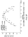
- Fig. 37 shows the relationship between each width-directional position of the defect and the relative value of the output signal when the subtraction circuits 62, absolute value circuits 63 and summing circuits 64 are removed and the detection signals from the magnetic sensors 7a are directly delivered to the arithmetic operation circuit 65.
- the measurement error at the same defect position can remarkably reduced.
- the S/N of the output signals is greatly improved.
- both magnetic sensors 7a undesirably detect the leakage magnetic flux due to the same defect.
- the distance E between the magnetic sensors 7a is too large, it is difficult to detect a common leakage magnetic flux due to the non-uniform magnetic permeability. Accordingly, there is an optimal range of the distance E between the magnetic sensors.
- the optimal range of the distance E between the magnetic sensors relates to the lift-off.
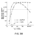
- Fig. 38 shows the relationship between a value (EL) obtained by multiplying the lift-off L by the distance E between magnetic sensors 7a, and a relative output of a sum signal input to the arithmetic operation circuit 65 at each value EL (mm) and a relative S/N of the sum signal.
- an optimal range of the value (EL) is 17 to 78 expressed by formula (7): 17 ⁇ EL ⁇ 78 (7)
- the optimal range of the distance E between the magnetic sensors is 6 to 16 mm.
- the subtraction circuits 62, absolute value circuits 63 and summing circuits 64 are constituted by ordinary analog circuits. However, these circuits may be constituted by, e.g. digital circuits.
- the distance E between the magnetic sensors for calculating the difference signal is set at a value determined by formula (7) in accordance with the lift-off L.
Landscapes
- Chemical & Material Sciences (AREA)
- Chemical Kinetics & Catalysis (AREA)
- Electrochemistry (AREA)
- Physics & Mathematics (AREA)
- Health & Medical Sciences (AREA)
- Life Sciences & Earth Sciences (AREA)
- Analytical Chemistry (AREA)
- Biochemistry (AREA)
- General Health & Medical Sciences (AREA)
- General Physics & Mathematics (AREA)
- Immunology (AREA)
- Pathology (AREA)
- Investigating Or Analyzing Materials By The Use Of Magnetic Means (AREA)
Abstract
Applications Claiming Priority (7)
| Application Number | Priority Date | Filing Date | Title |
|---|---|---|---|
| JP1356891 | 1991-02-04 | ||
| JP13568/91 | 1991-02-04 | ||
| JP23306/91 | 1991-02-18 | ||
| JP2330791 | 1991-02-18 | ||
| JP2330691 | 1991-02-18 | ||
| JP23307/91 | 1991-02-18 | ||
| PCT/JP1992/000096 WO1992014145A1 (fr) | 1991-02-04 | 1992-01-31 | Procede d'inspection magnetique et dispositif prevu a cet effet |
Publications (3)
| Publication Number | Publication Date |
|---|---|
| EP0523249A1 true EP0523249A1 (fr) | 1993-01-20 |
| EP0523249A4 EP0523249A4 (en) | 1993-08-11 |
| EP0523249B1 EP0523249B1 (fr) | 1997-11-05 |
Family
ID=27280323
Family Applications (1)
| Application Number | Title | Priority Date | Filing Date |
|---|---|---|---|
| EP92904249A Expired - Lifetime EP0523249B1 (fr) | 1991-02-04 | 1992-01-31 | Procede d'inspection magnetique et dispositif prevu a cet effet |
Country Status (6)
| Country | Link |
|---|---|
| US (2) | US5357198A (fr) |
| EP (1) | EP0523249B1 (fr) |
| AU (1) | AU1221092A (fr) |
| CA (1) | CA2079774A1 (fr) |
| DE (1) | DE69222989T2 (fr) |
| WO (1) | WO1992014145A1 (fr) |
Cited By (2)
| Publication number | Priority date | Publication date | Assignee | Title |
|---|---|---|---|---|
| US6057684A (en) * | 1995-10-31 | 2000-05-02 | Yoshihiro Murakami | Magnetic flaw detection apparatus using an E-shaped magnetic sensor and high-pass filter |
| US6774627B2 (en) | 2000-10-18 | 2004-08-10 | Kawasaki Steel Corporation | Leak magnetism detection sensor for magnetic flaw detection system |
Families Citing this family (21)
| Publication number | Priority date | Publication date | Assignee | Title |
|---|---|---|---|---|
| JPH08193980A (ja) * | 1995-01-19 | 1996-07-30 | Yoshihiro Murakami | 磁気探傷法及び、磁気探傷装置 |
| US5744955A (en) * | 1995-08-02 | 1998-04-28 | Booker; James R. | Apparatus and method of detecting loss of cross-sectional area of magnetic metallic strength members used in conductors such as aluminum conductor steel reinforced (ACSR) conductors |
| US5821749A (en) * | 1995-08-02 | 1998-10-13 | Booker; James R. | Reluctance change apparatus and method of detecting loss of cross-sectional area of magnetic metallic strength members used in conductors such as aluminum conductor steel reinforced ("ACSR") conductors |
| JP3309755B2 (ja) | 1997-02-25 | 2002-07-29 | 日本鋼管株式会社 | 継目無管の磁気探傷装置及びその方法 |
| RU2257571C1 (ru) * | 2004-06-08 | 2005-07-27 | Закрытое Акционерное Общество Научно-Производственное Предприятие "Нефтетрубосервис" | Способ магнитной дефектоскопии и устройство для его осуществления |
| US7218102B2 (en) * | 2004-10-07 | 2007-05-15 | Battelle Memorial Institute | Pipeline inspection apparatus and method |
| US8035373B2 (en) * | 2004-10-28 | 2011-10-11 | Toyo Kohan Co., Ltd. | Device and method for inspecting scratches on cell external case |
| US7804295B2 (en) * | 2005-04-28 | 2010-09-28 | Randel Brandstrom | Apparatus and method for detection of defects using flux leakage techniques |
| DE202007011834U1 (de) * | 2007-01-08 | 2007-11-15 | Asm Automation Sensorik Messtechnik Gmbh | Winkelsensor |
| US20110031961A1 (en) * | 2008-02-04 | 2011-02-10 | Durand Keith V | Endotracheal tube sensor |
| CN101419192B (zh) * | 2008-11-28 | 2012-05-09 | 华中科技大学 | 导磁构件超强磁化漏磁检测方法与装置 |
| US8368395B2 (en) * | 2008-12-17 | 2013-02-05 | Ndt Technologies, Inc. | Magnetic inspection device and method for detecting loss in metallic cross section |
| KR101765916B1 (ko) | 2010-12-31 | 2017-08-23 | 엘지이노텍 주식회사 | 전자 선반 라벨 및 배터리 잔량 관리 방법 |
| JP5550617B2 (ja) * | 2011-09-21 | 2014-07-16 | 株式会社日立製作所 | 漏洩磁束探傷装置 |
| CN104502442B (zh) * | 2014-08-28 | 2017-06-23 | 西红柿科技(武汉)有限公司 | 一种具有磁罩的漏磁检测仪 |
| RU2016106942A (ru) * | 2016-02-26 | 2017-08-29 | Акционерное общество "Диаконт" | Устройство, система и способ автоматизированного неразрушающего контроля металлических конструкций |
| JP2018009873A (ja) * | 2016-07-13 | 2018-01-18 | 株式会社Ihi | 探触子およびこれを備えた漏洩磁束探傷装置 |
| JP6547726B2 (ja) * | 2016-11-28 | 2019-07-24 | Jfeスチール株式会社 | 薄鋼帯の漏洩磁束探傷装置および探傷方法 |
| JP6908213B1 (ja) * | 2019-12-20 | 2021-07-21 | Jfeスチール株式会社 | 漏洩磁気検査装置および欠陥検査方法 |
| CN118330016B (zh) * | 2024-04-02 | 2025-01-28 | 宁夏大学 | 一种可基于实际漏磁工况调节磁屏蔽效果的提升检测灵敏度方法 |
| JP7747138B1 (ja) * | 2024-08-05 | 2025-10-01 | フジテック株式会社 | ロープテスタ |
Family Cites Families (17)
| Publication number | Priority date | Publication date | Assignee | Title |
|---|---|---|---|---|
| DE597671C (de) * | 1930-05-20 | 1934-05-29 | Franz Unger Dr | Vorrichtung zur Feststellung von Fehlerstellen in Werkstuecken |
| US3156862A (en) * | 1961-12-15 | 1964-11-10 | Assembly Products Inc | Electrical flaw detector apparatus having null plane positioned as well as electrically balanced coil arrangements |
| US3241058A (en) * | 1962-08-22 | 1966-03-15 | Api Instr Company | Flaw detecting apparatus having null plane positioned sensors which are series connected |
| US3469182A (en) * | 1967-06-23 | 1969-09-23 | Gkn Group Services Ltd | Flaw detecting apparatus with mechanical scanning of detection means |
| US3825820A (en) * | 1972-10-31 | 1974-07-23 | Magnaflux Corp | Gate circuit for non-destructive testing systems for indicating when test signals lie within predetermined limits |
| JPS5856830B2 (ja) * | 1973-05-10 | 1983-12-16 | エイエムエフ インコ−ポレ−テツド | カンジヨウブザイオヒハカイテキ ニ ケンサスル ホウホウ オヨビ ソウチ |
| JPS6020708B2 (ja) * | 1979-05-04 | 1985-05-23 | 新日本製鐵株式会社 | エツジ検出器 |
| DE3132808C2 (de) * | 1981-08-19 | 1984-01-26 | Nukem Gmbh, 6450 Hanau | "Vorrichtung zur zerstörungsfreien Prüfung ferromagnetischer Körper" |
| JPS6020708A (ja) * | 1983-07-12 | 1985-02-02 | 日新電機株式会社 | ガス絶縁開閉装置 |
| SU1302150A1 (ru) * | 1984-08-16 | 1987-04-07 | Институт сверхтвердых материалов АН УССР | Датчик неразрушающего контрол поверхностных слоев деталей |
| DE3435442A1 (de) * | 1984-09-27 | 1986-03-27 | Nukem Gmbh, 6450 Hanau | Verfahren und vorrichtung zur zerstoerungsfreien pruefung ferromagnetischer koerper mittels magnetisierung |
| GB8606564D0 (en) * | 1986-03-17 | 1986-04-23 | Atomic Energy Authority Uk | Magnetic discontinuity detection |
| US4775579A (en) * | 1987-11-05 | 1988-10-04 | James River Corporation Of Virginia | Hydroentangled elastic and nonelastic filaments |
| HU200031B (en) * | 1988-03-28 | 1990-03-28 | Tungsram Reszvenytarsasag | High-pressure discharge lamp |
| JPH089641Y2 (ja) * | 1989-01-30 | 1996-03-21 | 株式会社明電舎 | スチールベルトのクラック検出装置 |
| US5089776A (en) * | 1989-09-25 | 1992-02-18 | Nkk Corporation | Apparatus for detecting defects in a moving steel strip with a magnetizing yoke and a sensor placed on opposite sides of the strip |
| US5021738A (en) * | 1990-03-26 | 1991-06-04 | The United States Of America As Represented By The Secretary Of The Navy | Field variable, electronically controlled, nested coil eddy current probe |
-
1992
- 1992-01-31 CA CA002079774A patent/CA2079774A1/fr not_active Abandoned
- 1992-01-31 US US07/927,498 patent/US5357198A/en not_active Expired - Fee Related
- 1992-01-31 WO PCT/JP1992/000096 patent/WO1992014145A1/fr not_active Ceased
- 1992-01-31 EP EP92904249A patent/EP0523249B1/fr not_active Expired - Lifetime
- 1992-01-31 AU AU12210/92A patent/AU1221092A/en not_active Abandoned
- 1992-01-31 DE DE69222989T patent/DE69222989T2/de not_active Expired - Fee Related
-
1994
- 1994-07-15 US US08/276,517 patent/US5502382A/en not_active Expired - Fee Related
Non-Patent Citations (1)
| Title |
|---|
| See references of WO9214145A1 * |
Cited By (2)
| Publication number | Priority date | Publication date | Assignee | Title |
|---|---|---|---|---|
| US6057684A (en) * | 1995-10-31 | 2000-05-02 | Yoshihiro Murakami | Magnetic flaw detection apparatus using an E-shaped magnetic sensor and high-pass filter |
| US6774627B2 (en) | 2000-10-18 | 2004-08-10 | Kawasaki Steel Corporation | Leak magnetism detection sensor for magnetic flaw detection system |
Also Published As
| Publication number | Publication date |
|---|---|
| US5357198A (en) | 1994-10-18 |
| EP0523249B1 (fr) | 1997-11-05 |
| AU1221092A (en) | 1992-09-07 |
| DE69222989T2 (de) | 1998-06-04 |
| US5502382A (en) | 1996-03-26 |
| DE69222989D1 (de) | 1997-12-11 |
| WO1992014145A1 (fr) | 1992-08-20 |
| EP0523249A4 (en) | 1993-08-11 |
| CA2079774A1 (fr) | 1992-08-05 |
Similar Documents
| Publication | Publication Date | Title |
|---|---|---|
| EP0523249B1 (fr) | Procede d'inspection magnetique et dispositif prevu a cet effet | |
| US4634976A (en) | Barkhausen noise method for stress and defect detecting in hard steel | |
| US4659991A (en) | Method and apparatus for magnetically inspecting elongated objects for structural defects | |
| KR100246244B1 (ko) | 자기탐상장치 | |
| KR100671630B1 (ko) | 자기 탐상 장치의 누설 자기 검출 센서 및 스트립의온라인 탐상 방법 | |
| US5512821A (en) | Method and apparatus for magnetically detecting defects in an object with compensation for magnetic field shift by means of a compensating coil | |
| US5414353A (en) | Method and device for nondestructively inspecting elongated objects for structural defects using longitudinally arranged magnet means and sensor means disposed immediately downstream therefrom | |
| KR920007198B1 (ko) | 강철스트립의 자기결함 검사기 | |
| EP0469158B1 (fr) | Detecteur magnetique de defauts pour mince bande en acier | |
| US20040041560A1 (en) | Method, system and apparatus for ferromagnetic wall monitoring | |
| US20190285585A1 (en) | Method and apparatus for evaluating damage to magnetic linear body | |
| US6133731A (en) | Method and apparatus for the on-line measurement of the strength of metal cables | |
| JPH1183808A (ja) | 漏洩磁束探傷方法 | |
| JPH0572180A (ja) | 磁気探傷方法およびその装置 | |
| US3588683A (en) | Method and apparatus for nondestructive testing of ferromagnetic articles,to determine the location,orientation and depth of defects in such articles utilizing the barkhausen effect | |
| JP2848081B2 (ja) | 磁気探傷装置 | |
| JP2639250B2 (ja) | 磁気探傷装置 | |
| JPWO1992014145A1 (ja) | 磁気探傷方法及びその装置 | |
| JPH04296648A (ja) | 磁気探傷方法および装置 | |
| EP0544911B1 (fr) | Dispositif pour la detection d'un flux magnetique | |
| JP2526748B2 (ja) | 金属帯の異常部検出装置 | |
| CA2054718C (fr) | Appareil d'inspection magnetique pour feuillard mince | |
| JPH07146277A (ja) | 非破壊検査装置 | |
| JPH085610A (ja) | 磁気検出方法及びその装置 | |
| RU2032898C1 (ru) | Способ магнитного контроля дефектов длинномерных ферромагнитных изделий |
Legal Events
| Date | Code | Title | Description |
|---|---|---|---|
| PUAI | Public reference made under article 153(3) epc to a published international application that has entered the european phase |
Free format text: ORIGINAL CODE: 0009012 |
|
| 17P | Request for examination filed |
Effective date: 19921002 |
|
| AK | Designated contracting states |
Kind code of ref document: A1 Designated state(s): DE FR GB |
|
| A4 | Supplementary search report drawn up and despatched |
Effective date: 19930621 |
|
| AK | Designated contracting states |
Kind code of ref document: A4 Designated state(s): DE FR GB |
|
| 17Q | First examination report despatched |
Effective date: 19950802 |
|
| GRAG | Despatch of communication of intention to grant |
Free format text: ORIGINAL CODE: EPIDOS AGRA |
|
| GRAH | Despatch of communication of intention to grant a patent |
Free format text: ORIGINAL CODE: EPIDOS IGRA |
|
| GRAH | Despatch of communication of intention to grant a patent |
Free format text: ORIGINAL CODE: EPIDOS IGRA |
|
| GRAA | (expected) grant |
Free format text: ORIGINAL CODE: 0009210 |
|
| AK | Designated contracting states |
Kind code of ref document: B1 Designated state(s): DE FR GB |
|
| PG25 | Lapsed in a contracting state [announced via postgrant information from national office to epo] |
Ref country code: FR Free format text: LAPSE BECAUSE OF FAILURE TO SUBMIT A TRANSLATION OF THE DESCRIPTION OR TO PAY THE FEE WITHIN THE PRESCRIBED TIME-LIMIT Effective date: 19971105 |
|
| REF | Corresponds to: |
Ref document number: 69222989 Country of ref document: DE Date of ref document: 19971211 |
|
| EN | Fr: translation not filed | ||
| PLBE | No opposition filed within time limit |
Free format text: ORIGINAL CODE: 0009261 |
|
| STAA | Information on the status of an ep patent application or granted ep patent |
Free format text: STATUS: NO OPPOSITION FILED WITHIN TIME LIMIT |
|
| 26N | No opposition filed | ||
| PGFP | Annual fee paid to national office [announced via postgrant information from national office to epo] |
Ref country code: GB Payment date: 19990204 Year of fee payment: 8 |
|
| PGFP | Annual fee paid to national office [announced via postgrant information from national office to epo] |
Ref country code: DE Payment date: 19990205 Year of fee payment: 8 |
|
| PG25 | Lapsed in a contracting state [announced via postgrant information from national office to epo] |
Ref country code: GB Free format text: LAPSE BECAUSE OF NON-PAYMENT OF DUE FEES Effective date: 20000131 |
|
| GBPC | Gb: european patent ceased through non-payment of renewal fee |
Effective date: 20000131 |
|
| PG25 | Lapsed in a contracting state [announced via postgrant information from national office to epo] |
Ref country code: DE Free format text: LAPSE BECAUSE OF NON-PAYMENT OF DUE FEES Effective date: 20001101 |