EP0523509A2 - Procédé et dispositif pour la fabrication de tubes enroulés - Google Patents
Procédé et dispositif pour la fabrication de tubes enroulés Download PDFInfo
- Publication number
- EP0523509A2 EP0523509A2 EP92111451A EP92111451A EP0523509A2 EP 0523509 A2 EP0523509 A2 EP 0523509A2 EP 92111451 A EP92111451 A EP 92111451A EP 92111451 A EP92111451 A EP 92111451A EP 0523509 A2 EP0523509 A2 EP 0523509A2
- Authority
- EP
- European Patent Office
- Prior art keywords
- cylinder
- band
- carrier film
- joint
- reaction mixture
- Prior art date
- Legal status (The legal status is an assumption and is not a legal conclusion. Google has not performed a legal analysis and makes no representation as to the accuracy of the status listed.)
- Granted
Links
Images




Classifications
-
- B—PERFORMING OPERATIONS; TRANSPORTING
- B29—WORKING OF PLASTICS; WORKING OF SUBSTANCES IN A PLASTIC STATE IN GENERAL
- B29C—SHAPING OR JOINING OF PLASTICS; SHAPING OF MATERIAL IN A PLASTIC STATE, NOT OTHERWISE PROVIDED FOR; AFTER-TREATMENT OF THE SHAPED PRODUCTS, e.g. REPAIRING
- B29C66/00—General aspects of processes or apparatus for joining preformed parts
- B29C66/01—General aspects dealing with the joint area or with the area to be joined
- B29C66/05—Particular design of joint configurations
- B29C66/10—Particular design of joint configurations particular design of the joint cross-sections
- B29C66/11—Joint cross-sections comprising a single joint-segment, i.e. one of the parts to be joined comprising a single joint-segment in the joint cross-section
- B29C66/114—Single butt joints
- B29C66/1142—Single butt to butt joints
-
- B—PERFORMING OPERATIONS; TRANSPORTING
- B29—WORKING OF PLASTICS; WORKING OF SUBSTANCES IN A PLASTIC STATE IN GENERAL
- B29C—SHAPING OR JOINING OF PLASTICS; SHAPING OF MATERIAL IN A PLASTIC STATE, NOT OTHERWISE PROVIDED FOR; AFTER-TREATMENT OF THE SHAPED PRODUCTS, e.g. REPAIRING
- B29C53/00—Shaping by bending, folding, twisting, straightening or flattening; Apparatus therefor
- B29C53/56—Winding and joining, e.g. winding spirally
- B29C53/58—Winding and joining, e.g. winding spirally helically
- B29C53/581—Winding and joining, e.g. winding spirally helically using sheets or strips consisting principally of plastics material
-
- B—PERFORMING OPERATIONS; TRANSPORTING
- B29—WORKING OF PLASTICS; WORKING OF SUBSTANCES IN A PLASTIC STATE IN GENERAL
- B29C—SHAPING OR JOINING OF PLASTICS; SHAPING OF MATERIAL IN A PLASTIC STATE, NOT OTHERWISE PROVIDED FOR; AFTER-TREATMENT OF THE SHAPED PRODUCTS, e.g. REPAIRING
- B29C53/00—Shaping by bending, folding, twisting, straightening or flattening; Apparatus therefor
- B29C53/56—Winding and joining, e.g. winding spirally
- B29C53/58—Winding and joining, e.g. winding spirally helically
- B29C53/60—Winding and joining, e.g. winding spirally helically using internal forming surfaces, e.g. mandrels
- B29C53/607—Winding and joining, e.g. winding spirally helically using internal forming surfaces, e.g. mandrels having driving means for advancing the wound articles, e.g. belts, rolls
-
- B—PERFORMING OPERATIONS; TRANSPORTING
- B29—WORKING OF PLASTICS; WORKING OF SUBSTANCES IN A PLASTIC STATE IN GENERAL
- B29C—SHAPING OR JOINING OF PLASTICS; SHAPING OF MATERIAL IN A PLASTIC STATE, NOT OTHERWISE PROVIDED FOR; AFTER-TREATMENT OF THE SHAPED PRODUCTS, e.g. REPAIRING
- B29C53/00—Shaping by bending, folding, twisting, straightening or flattening; Apparatus therefor
- B29C53/80—Component parts, details or accessories; Auxiliary operations
- B29C53/8008—Component parts, details or accessories; Auxiliary operations specially adapted for winding and joining
- B29C53/8083—Improving bonding of wound materials or layers
-
- B—PERFORMING OPERATIONS; TRANSPORTING
- B29—WORKING OF PLASTICS; WORKING OF SUBSTANCES IN A PLASTIC STATE IN GENERAL
- B29C—SHAPING OR JOINING OF PLASTICS; SHAPING OF MATERIAL IN A PLASTIC STATE, NOT OTHERWISE PROVIDED FOR; AFTER-TREATMENT OF THE SHAPED PRODUCTS, e.g. REPAIRING
- B29C65/00—Joining or sealing of preformed parts, e.g. welding of plastics materials; Apparatus therefor
- B29C65/48—Joining or sealing of preformed parts, e.g. welding of plastics materials; Apparatus therefor using adhesives, i.e. using supplementary joining material; solvent bonding
- B29C65/4805—Joining or sealing of preformed parts, e.g. welding of plastics materials; Apparatus therefor using adhesives, i.e. using supplementary joining material; solvent bonding characterised by the type of adhesives
- B29C65/483—Reactive adhesives, e.g. chemically curing adhesives
-
- B—PERFORMING OPERATIONS; TRANSPORTING
- B29—WORKING OF PLASTICS; WORKING OF SUBSTANCES IN A PLASTIC STATE IN GENERAL
- B29C—SHAPING OR JOINING OF PLASTICS; SHAPING OF MATERIAL IN A PLASTIC STATE, NOT OTHERWISE PROVIDED FOR; AFTER-TREATMENT OF THE SHAPED PRODUCTS, e.g. REPAIRING
- B29C65/00—Joining or sealing of preformed parts, e.g. welding of plastics materials; Apparatus therefor
- B29C65/48—Joining or sealing of preformed parts, e.g. welding of plastics materials; Apparatus therefor using adhesives, i.e. using supplementary joining material; solvent bonding
- B29C65/52—Joining or sealing of preformed parts, e.g. welding of plastics materials; Apparatus therefor using adhesives, i.e. using supplementary joining material; solvent bonding characterised by the way of applying the adhesive
- B29C65/54—Joining or sealing of preformed parts, e.g. welding of plastics materials; Apparatus therefor using adhesives, i.e. using supplementary joining material; solvent bonding characterised by the way of applying the adhesive between pre-assembled parts
-
- B—PERFORMING OPERATIONS; TRANSPORTING
- B29—WORKING OF PLASTICS; WORKING OF SUBSTANCES IN A PLASTIC STATE IN GENERAL
- B29C—SHAPING OR JOINING OF PLASTICS; SHAPING OF MATERIAL IN A PLASTIC STATE, NOT OTHERWISE PROVIDED FOR; AFTER-TREATMENT OF THE SHAPED PRODUCTS, e.g. REPAIRING
- B29C66/00—General aspects of processes or apparatus for joining preformed parts
- B29C66/01—General aspects dealing with the joint area or with the area to be joined
- B29C66/05—Particular design of joint configurations
- B29C66/305—Decorative or coloured joints
-
- B—PERFORMING OPERATIONS; TRANSPORTING
- B29—WORKING OF PLASTICS; WORKING OF SUBSTANCES IN A PLASTIC STATE IN GENERAL
- B29C—SHAPING OR JOINING OF PLASTICS; SHAPING OF MATERIAL IN A PLASTIC STATE, NOT OTHERWISE PROVIDED FOR; AFTER-TREATMENT OF THE SHAPED PRODUCTS, e.g. REPAIRING
- B29C66/00—General aspects of processes or apparatus for joining preformed parts
- B29C66/70—General aspects of processes or apparatus for joining preformed parts characterised by the composition, physical properties or the structure of the material of the parts to be joined; Joining with non-plastics material
- B29C66/71—General aspects of processes or apparatus for joining preformed parts characterised by the composition, physical properties or the structure of the material of the parts to be joined; Joining with non-plastics material characterised by the composition of the plastics material of the parts to be joined
-
- B—PERFORMING OPERATIONS; TRANSPORTING
- B29—WORKING OF PLASTICS; WORKING OF SUBSTANCES IN A PLASTIC STATE IN GENERAL
- B29C—SHAPING OR JOINING OF PLASTICS; SHAPING OF MATERIAL IN A PLASTIC STATE, NOT OTHERWISE PROVIDED FOR; AFTER-TREATMENT OF THE SHAPED PRODUCTS, e.g. REPAIRING
- B29C66/00—General aspects of processes or apparatus for joining preformed parts
- B29C66/80—General aspects of machine operations or constructions and parts thereof
- B29C66/83—General aspects of machine operations or constructions and parts thereof characterised by the movement of the joining or pressing tools
- B29C66/834—General aspects of machine operations or constructions and parts thereof characterised by the movement of the joining or pressing tools moving with the parts to be joined
- B29C66/8341—Roller, cylinder or drum types; Band or belt types; Ball types
- B29C66/83411—Roller, cylinder or drum types
- B29C66/83413—Roller, cylinder or drum types cooperating rollers, cylinders or drums
-
- B—PERFORMING OPERATIONS; TRANSPORTING
- B29—WORKING OF PLASTICS; WORKING OF SUBSTANCES IN A PLASTIC STATE IN GENERAL
- B29C—SHAPING OR JOINING OF PLASTICS; SHAPING OF MATERIAL IN A PLASTIC STATE, NOT OTHERWISE PROVIDED FOR; AFTER-TREATMENT OF THE SHAPED PRODUCTS, e.g. REPAIRING
- B29C66/00—General aspects of processes or apparatus for joining preformed parts
- B29C66/80—General aspects of machine operations or constructions and parts thereof
- B29C66/83—General aspects of machine operations or constructions and parts thereof characterised by the movement of the joining or pressing tools
- B29C66/834—General aspects of machine operations or constructions and parts thereof characterised by the movement of the joining or pressing tools moving with the parts to be joined
- B29C66/8341—Roller, cylinder or drum types; Band or belt types; Ball types
- B29C66/83431—Roller, cylinder or drum types; Band or belt types; Ball types rollers, cylinders or drums cooperating with bands or belts
- B29C66/83433—Roller, cylinder or drum types; Band or belt types; Ball types rollers, cylinders or drums cooperating with bands or belts the contact angle between said rollers, cylinders or drums and said bands or belts being a non-zero angle
-
- B—PERFORMING OPERATIONS; TRANSPORTING
- B29—WORKING OF PLASTICS; WORKING OF SUBSTANCES IN A PLASTIC STATE IN GENERAL
- B29C—SHAPING OR JOINING OF PLASTICS; SHAPING OF MATERIAL IN A PLASTIC STATE, NOT OTHERWISE PROVIDED FOR; AFTER-TREATMENT OF THE SHAPED PRODUCTS, e.g. REPAIRING
- B29C65/00—Joining or sealing of preformed parts, e.g. welding of plastics materials; Apparatus therefor
- B29C65/48—Joining or sealing of preformed parts, e.g. welding of plastics materials; Apparatus therefor using adhesives, i.e. using supplementary joining material; solvent bonding
- B29C65/52—Joining or sealing of preformed parts, e.g. welding of plastics materials; Apparatus therefor using adhesives, i.e. using supplementary joining material; solvent bonding characterised by the way of applying the adhesive
- B29C65/54—Joining or sealing of preformed parts, e.g. welding of plastics materials; Apparatus therefor using adhesives, i.e. using supplementary joining material; solvent bonding characterised by the way of applying the adhesive between pre-assembled parts
- B29C65/546—Joining or sealing of preformed parts, e.g. welding of plastics materials; Apparatus therefor using adhesives, i.e. using supplementary joining material; solvent bonding characterised by the way of applying the adhesive between pre-assembled parts by gravity, e.g. by pouring
-
- B—PERFORMING OPERATIONS; TRANSPORTING
- B29—WORKING OF PLASTICS; WORKING OF SUBSTANCES IN A PLASTIC STATE IN GENERAL
- B29C—SHAPING OR JOINING OF PLASTICS; SHAPING OF MATERIAL IN A PLASTIC STATE, NOT OTHERWISE PROVIDED FOR; AFTER-TREATMENT OF THE SHAPED PRODUCTS, e.g. REPAIRING
- B29C66/00—General aspects of processes or apparatus for joining preformed parts
- B29C66/40—General aspects of joining substantially flat articles, e.g. plates, sheets or web-like materials; Making flat seams in tubular or hollow articles; Joining single elements to substantially flat surfaces
- B29C66/41—Joining substantially flat articles ; Making flat seams in tubular or hollow articles
- B29C66/43—Joining a relatively small portion of the surface of said articles
- B29C66/432—Joining a relatively small portion of the surface of said articles for making tubular articles or closed loops, e.g. by joining several sheets ; for making hollow articles or hollow preforms
- B29C66/4322—Joining a relatively small portion of the surface of said articles for making tubular articles or closed loops, e.g. by joining several sheets ; for making hollow articles or hollow preforms by joining a single sheet to itself
-
- B—PERFORMING OPERATIONS; TRANSPORTING
- B29—WORKING OF PLASTICS; WORKING OF SUBSTANCES IN A PLASTIC STATE IN GENERAL
- B29C—SHAPING OR JOINING OF PLASTICS; SHAPING OF MATERIAL IN A PLASTIC STATE, NOT OTHERWISE PROVIDED FOR; AFTER-TREATMENT OF THE SHAPED PRODUCTS, e.g. REPAIRING
- B29C66/00—General aspects of processes or apparatus for joining preformed parts
- B29C66/40—General aspects of joining substantially flat articles, e.g. plates, sheets or web-like materials; Making flat seams in tubular or hollow articles; Joining single elements to substantially flat surfaces
- B29C66/41—Joining substantially flat articles ; Making flat seams in tubular or hollow articles
- B29C66/43—Joining a relatively small portion of the surface of said articles
- B29C66/432—Joining a relatively small portion of the surface of said articles for making tubular articles or closed loops, e.g. by joining several sheets ; for making hollow articles or hollow preforms
- B29C66/4329—Joining a relatively small portion of the surface of said articles for making tubular articles or closed loops, e.g. by joining several sheets ; for making hollow articles or hollow preforms the joint lines being transversal but non-orthogonal with respect to the axis of said tubular articles, i.e. being oblique
-
- B—PERFORMING OPERATIONS; TRANSPORTING
- B29—WORKING OF PLASTICS; WORKING OF SUBSTANCES IN A PLASTIC STATE IN GENERAL
- B29K—INDEXING SCHEME ASSOCIATED WITH SUBCLASSES B29B, B29C OR B29D, RELATING TO MOULDING MATERIALS OR TO MATERIALS FOR MOULDS, REINFORCEMENTS, FILLERS OR PREFORMED PARTS, e.g. INSERTS
- B29K2075/00—Use of PU, i.e. polyureas or polyurethanes or derivatives thereof, as moulding material
Definitions
- the invention relates to a method and a device for producing wound plastic pipes, a plastic band being wound onto a cylinder at a winding angle and the adjacent windings being connected to one another by pouring out the joint therebetween, as in DE-A-2 423 223 known.
- prefabricated tapes made of plastic are wound onto a cylinder in the deformable state and the turns are welded to one another.
- the cylinder has a rubber coating and is heated before winding, and the tube can be removed after cooling. So this is a discontinuous process with low cost-effectiveness.
- the object is to improve the technology for producing wound plastic pipes by simplifying the procedure and the device.
- This object is achieved in that a polyurethane reaction mixture is poured onto a linearly moving carrier film strip to form a plastic and forms the band by curing, and in that the adjacent windings are connected by pouring out the joint with a polyurethane reaction mixture and the tube thus formed by the cylinder is stripped continuously.
- the particular advantage of the new method is that it can be carried out continuously, that the tape can be produced immediately before winding and that the tape is surprisingly hardened enough so that pressure can be exerted against the last turn and that tube in the process of formation can continuously push it away from the cylinder, which was not foreseeable, because there is strong friction between the windings and the cylinder.
- reinforcing materials in the form of tapes, foils, fabrics or reinforcements made from cut fibers or powders on an organic or inorganic basis can be added and embedded in the reaction mixture.
- Reinforcing or fillers in powder form can also be mixed into one of the reaction components or before the reaction mixture is added to it, or it can be poured onto the carrier film beforehand, or after the reaction mixture has been applied to the carrier film, it can be sprinkled onto the reaction mixture, into which it then sinks.
- Chalk, slate flour, quartz flour, spar, aluminum hydroxide, wood flour, crushed plastics and possibly also recycling material are suitable as fillers.
- Additional tapes made of plastic or metal foil can also be placed under, inserted or laid on and cast and processed when the tape is being cast.
- foil tapes When foil tapes are inserted, it is expedient to use those with a perforation so that the reaction mixture can pass through can.
- the winding angle ie the angle between the fed tape and the axis of the cylinder, is less than 90 °.
- the carrier film preferably consists of a release-friendly plastic, such as polyethylene, polypropylene, polytetrafluoroethylene, or of a paper coated with a release agent, for example silicone.
- a metal foil can also be used as a carrier foil, soapy water, for example, can serve as a release agent. Due to the strength of this metal foil, it can be used as an endless belt or can also be recycled as a finite belt.
- the joint between the turns is preferably filled with the same polyurethane reaction mixture by means of a second pouring device, preferably at the zenith of the cylinder or the winding.
- the stripping of the tube, which is being manufactured, from the cylinder is preferably carried out by guides which press in the discharge direction in accordance with the winding angle and press against the last winding applied.
- These guides consist of runners or rollers, for example.
- the carrier film strip has an edge which projects beyond the width of the band, at least on the side facing away from the discharge direction.
- the carrier film strip is folded up like a trough at the side and the polyurethane reaction mixture is poured into the trough formed in this way, and before the tape is wound up, the edge facing away from the discharge direction is laid flat and the edge pointing in the discharge direction is folded under the tape formed.
- the carrier film strip is preferably pulled off after the tube has left the cylinder.
- profiles provided with undercuts are introduced when the joint is poured out.
- Profiles of this type can also be produced when the joint is poured out by means of contouring aids, for example a double V-belt drive that moves along.
- Such profiles can serve as a spacer or anchoring, for example for a pipe jacket. They consist, for example, of plastic, metal or rigid fiber structures or the joint compound itself.
- Such tapes can be wound in layers in opposite directions, with other layers being able to be applied between the layers of the tapes, for example an intermediate layer made of a polyurethane reaction mixture or a rigid polyurethane foam layer for thermal insulation. In both cases, appropriate reaction mixtures which harden on the cylinder are preferably used. It goes without saying that reinforcement inserts can also be incorporated into such intermediate layers, for example windings made of rovings or fiber fabrics and the like. When applying several layers of tapes, it is usually necessary that the carrier film strips are removed from the second layer.
- Suitable polyurethane casting compounds for this purpose are those as described in "Kunststoff-Handbuch '', Volume VII, Polyurethane, Carl-Hanser-Verlag (1966), on page 241 in Table 31, right column to accelerate the system advantageously by adding 0.5 to 2 g of amine catalysts, for example by adding N, N-dimethylcyclohexamine.
- a new device for producing wound pipes from a band of plastic by connecting the turns of this band starts from a cylinder provided with a rotary drive with a discharge device for the pipe.
- this cylinder is preceded by an unwinding station for a carrier film strip and a pouring device for a polyurethane reaction mixture is arranged over the transport path of the carrier film strip, and that a further pouring device is provided above the cylinder for pouring out the joint between the turns.
- the band of plastic only needs to be manufactured immediately before the winding process, so that storage and other operations are eliminated.
- This method of manufacture is also inexpensive because it is also possible to use tapes which, once the plastic has completely hardened, would no longer be able to be wound.
- this is possible with the new device because, taking into account the winding speed, the time required for the belt to be transported from the point of application of the reaction mixture to the winding point can be adjusted by selecting the distance of the point of application from the winding point so that it is still in place during winding is sufficiently deformable.
- An alternative embodiment of the device is characterized by a fixed cylinder with an interruption in its jacket, a drive roller acting on the windings of the belt being arranged in the interruption, as well as by an unwinding station for a carrier film strip upstream of the cylinder and a casting device for a polyurethane reaction mixture over the transport path of the carrier film strip and through a further casting device over the cylinder for pouring out the joint between the turns.
- guides are preferably assigned to the cylinder as a discharge device for the tape to be wound, which guides are set at the winding angle.
- These guides consist of runners, rails or rollers and press the band or the turns and thus the tube being formed down from the cylinder.
- these guides are largely relieved if the drive rollers are set so that they turn the windings both radially and axially, i.e. under the winding angle. Further extraction aids can be provided on the already finished pipe.
- a pull-off device must be provided for pulling off the carrier film strip, if this is desired. It should be placed at the end of the cylinder or the carrier film strip to be removed is to be led back through the cylinder.
- the unwinding station for the carrier film and the casting device must lie on the transport path determined by the winding angle.
- the carrier film strip is to be folded up laterally in a trough-like manner, appropriate folding devices must be provided. If the edge facing away from the pull-off direction is to be laid flat and the edge pointing in the pull-off direction is to be folded under the band formed, guides must be provided for this.
- an unwinding station for a carrier film strip and a casting device must be provided for each tape. Whether a further pouring device for pouring out the joint between the turns or a pouring device that completely covers the joints and turns over the entire strip depends on the desired pipe structure. If further intermediate layers, for example a polyurethane foam insulating layer, are to be applied, a corresponding application device is provided for a foamable reaction mixture over the cylinder. If it is an intermediate layer, this feed device must be provided in front of the feed device or the feed point for the next layer of a tape, at such a distance that the reaction mixture can cure beforehand to form a load-bearing foam. These are special configurations of the device.
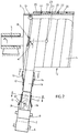
- the device consists of a cylinder 2, which can be set in rotation by means of a rotary drive 1 and whose jacket 3 has the inside diameter of the pipe 4 to be manufactured.
- a rotary drive 1 At an angle ⁇ of 80 ° to the axis 5 of the cylinder 2, an unwinding station 6 for a carrier film strip 7, which is guided over a deflection roller 8, is arranged.
- a second unwinding station 9 for a reinforcing fabric 10 and a deflection roller 11 are provided above the carrier film strip 7.
- a folding device 12 serves to fold up the edges 13, 14 of the carrier film strip 7 and to guide the folded edges 13, 14 laterally in the region of a casting device 15 arranged above for a polyurethane reaction mixture 17 forming a band 16, this folding device 12 shortly before the cylinder 2 is designed that the edge 13 facing away from the discharge side of the tube 4 is laid flat again and the edge 14 is folded under the band 16 by 180 ° and thus no longer protrudes.
- guides in the form of runners 18 and rollers 19 are arranged over the circumference of the cylinder jacket 3 on a frame frame, not shown, which bear against the first turn 20.
- a further casting device 21 is arranged above the zenith of the cylinder 2 and fills the joint 22 between the turns 20 with a polyurethane reaction mixture 23.
- extraction aids are assigned to the already manufactured tube 4.
- the carrier film strip 7 with its folded-up edges 13 and 14 can be seen in the folding device 12, which form a trough 24 in which the band 16 which is being solidified lies.
- the edge 14 is folded inwards so that the band 16 is chamfered.
- the band 16 has already hardened, the left edge 13 of the carrier film 7 projecting beyond the band 16, while its right edge 14 is partially pulled off the underside of the band 16 and is folded down by 180 °.
- turns 31 are shown, the band 32 being beveled on one side.
- a profile 34 with undercuts 35 is placed over the joint 33 formed and is also cast into the joint material 36.
- a profile 41 is also cast into the joint material 42.
- the profile 41 here has a semicircular cross section.
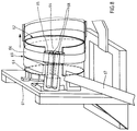
- a cylinder 62 is attached to a stand 61 as a stator.
- the jacket 63 of the cylinder 62 has an interruption 64 in which one Drive roller 65 abuts against the inside of the windings 66 of the band 67 and allows them to rotate around the cylinder 62.
- counter-pressure rollers 68 press against the windings 66 from the outside.
- the unwinding station for the carrier film strip, the folding device and the casting device correspond to those of the device according to FIGS. 1 and 2 and have been omitted here.
- the joint 69 between the turns 66 is poured out with the same casting compound from which the band 67 is made.
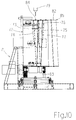
- a cylinder 72 is attached to a stand 71 as a stator.
- the jacket 73 of the cylinder 72 has an opening 74 for the execution of an endless steel strip 75 serving as a separating film from the inside and an opening 76 for reinserting this steel strip 75 into the interior, where it is returned to the opening 74.
- This steel strip 75 encloses the jacket 73 with more than one turn 77.
- a casting device 79 for a polyurethane reaction mixture is arranged above this steel strip 75.
- Upstream of the cylinder 72 is an endless conveyor belt 80, over which a polyurethane casting device 81 is also arranged.
- the polyurethane belt 82 which is applied to the steel belt 75 and is driven by the roller 83, forms on this driven conveyor belt 80.
- the joint 84 between the turns 85 is filled with the same mass from which the band 82 is made.
- a double V-belt 78 gives the contour when the joint 84 is cast.
- the cylinder 2 of 1000 mm in diameter rotates at 1 min ⁇ 1.
- the tape 16 is fed to it at a winding angle of 86 °.
- the carrier film 7, which has a polyethylene coating is unwound from the unwinding station 6 and transported in the direction of the cylinder 2 via a deflection roller 8. It is inserted into the folding device 12, which folds up the edges 13 and 14 of the carrier film 7, so that a trough 24 is formed.
- a reinforcing belt 10 made of glass fiber fabric is fed and inserted from an unwinding station 9 via a deflection roller 11, and a polyurethane reaction mixture is poured onto it by means of a casting device 15. Suitable reaction mixtures are described below.
- the reaction mixture forms the band 16.
- the edge 13 is laid flat again and the edge 14 is folded under the band 16 by 180 °.
- the last turn 20 lies on the flattened edge 13 of the previous turn 20.
- the winding process is supported by guides in the form of runners 18 and rollers 19, which at the same time advance the endless tube 4 that is being manufactured in the axial direction of cylinder 2.
- the joint 22 formed during winding between the windings 20 is poured out with a polyurethane reaction mixture 23 by means of a second casting device 21.
- the carrier film 7 is removed.
- the pipe 4 is transported in the axial direction by means of additional extraction aids and the endless strand is then cut to the desired pipe lengths.
- FIGS. 8 and 9 The device according to FIGS. 8 and 9 is used.
- the plastic band 67 is produced and guided as in process example 1 or in the device according to FIGS. 1 and 2.
- the windings 66 lying around the jacket 63 of the cylinder 62 are driven here by the drive roller 65. so that the pipe being manufactured rotates around the stationary cylinder 62, the friction between the jacket 63 and the windings 66 being reduced by lubricants.
- the grout 69 between the windings 66 is also cast according to process example 1 or according to the device according to FIGS. 1 and 2.
- the isocyanate index is set by varying the amount of the polyisocyanate mixture. 100 parts by weight of the mixture per 100 parts by weight of polyol II correspond to an isocyanate index of 660; 200 parts by weight per 100 parts by weight of polyol II with an isocyanate index of 1330.
Landscapes
- Engineering & Computer Science (AREA)
- Mechanical Engineering (AREA)
- Chemical & Material Sciences (AREA)
- Chemical Kinetics & Catalysis (AREA)
- General Chemical & Material Sciences (AREA)
- Casting Or Compression Moulding Of Plastics Or The Like (AREA)
- Shaping Of Tube Ends By Bending Or Straightening (AREA)
- Moulding By Coating Moulds (AREA)
- Coating With Molten Metal (AREA)
Applications Claiming Priority (2)
| Application Number | Priority Date | Filing Date | Title |
|---|---|---|---|
| DE4123920 | 1991-07-19 | ||
| DE4123920A DE4123920C2 (de) | 1991-07-19 | 1991-07-19 | Verfahren und Vorrichtung zum Herstellen von gewickelten Rohren |
Publications (3)
| Publication Number | Publication Date |
|---|---|
| EP0523509A2 true EP0523509A2 (fr) | 1993-01-20 |
| EP0523509A3 EP0523509A3 (en) | 1993-06-02 |
| EP0523509B1 EP0523509B1 (fr) | 1995-09-27 |
Family
ID=6436514
Family Applications (1)
| Application Number | Title | Priority Date | Filing Date |
|---|---|---|---|
| EP92111451A Expired - Lifetime EP0523509B1 (fr) | 1991-07-19 | 1992-07-06 | Procédé et dispositif pour la fabrication de tubes enroulés |
Country Status (6)
| Country | Link |
|---|---|
| EP (1) | EP0523509B1 (fr) |
| JP (1) | JPH05200857A (fr) |
| AT (1) | ATE128408T1 (fr) |
| CA (1) | CA2073956A1 (fr) |
| DE (2) | DE4123920C2 (fr) |
| DK (1) | DK0523509T3 (fr) |
Cited By (8)
| Publication number | Priority date | Publication date | Assignee | Title |
|---|---|---|---|---|
| DE4325653A1 (de) * | 1993-07-30 | 1995-02-02 | Bayer Ag | Verfahren und Vorrichtung zum Beschichten eines um eine Achse rotierenden Körpers |
| US5601881A (en) * | 1993-07-30 | 1997-02-11 | Bayer Aktiengesellschaft | Method and device for coating a body rotating about an axis |
| EP1208996A3 (fr) * | 2000-11-20 | 2004-07-28 | Heidelberger Druckmaschinen Aktiengesellschaft | Appareil pour la production de blanchets d'impression tubulaires |
| FR2850368A1 (fr) * | 2003-01-23 | 2004-07-30 | Eads Space Transportation Sa | Procede de depose sur un support de couches fibreuses successives inclinees, a partir d'une bande continue |
| EP1685946A1 (fr) * | 2005-01-27 | 2006-08-02 | NORRES Schlauchtechnik GmbH & Co. KG | Procédé de fabrication d'un tuyau à base de polyuréthane thermoplastique |
| US7824595B2 (en) | 2004-08-13 | 2010-11-02 | Perma-Pipe, Inc. | Method and system for cast molding a fluid conduit |
| CN109263095A (zh) * | 2018-11-21 | 2019-01-25 | 天津市锦业科技有限公司 | 多功能聚氨酯连续浇注聚乙烯保温管生产线 |
| CN114043712A (zh) * | 2021-10-15 | 2022-02-15 | 镇江奥立特机械制造有限公司 | 一种多级智能柔性碳纤维制造传动设备 |
Families Citing this family (1)
| Publication number | Priority date | Publication date | Assignee | Title |
|---|---|---|---|---|
| RU2687456C1 (ru) * | 2018-07-11 | 2019-05-13 | Акционерное общество "Научно-производственное объединение "СПЛАВ" | Способ формирования покрытия внутри вращающейся вокруг оси оболочки |
Family Cites Families (10)
| Publication number | Priority date | Publication date | Assignee | Title |
|---|---|---|---|---|
| US3607492A (en) * | 1965-05-20 | 1971-09-21 | Ici Australia Ltd | Process for preparing composite tube |
| GB1245068A (en) * | 1969-02-04 | 1971-09-02 | Tigers Rubber Co Ltd | Apparatus for continuously making a hose |
| FR2071401A5 (fr) * | 1969-12-29 | 1971-09-17 | Biancamaria Joseph | |
| DK129638B (da) * | 1970-08-21 | 1974-11-04 | Drostholm F H | Fremgangsmåde og apparat til ekstrudering og/eller vikling af fiberarmerede uendeligt lange plastrør. |
| US4011354A (en) * | 1972-03-22 | 1977-03-08 | Frede Hilmar Drostholm | Method and apparatus for making tubular resin elements such as pipes |
| DE2308418B2 (de) * | 1972-06-21 | 1976-04-08 | Petzetakis, Aristovoulos George, Moschaton, Piräus (Griechenland) | Verfahren und vorrichtung zum herstellen eines insbesondere grosskalibrigen rohres aus thermoplastischem kunststoff |
| DE2423223C3 (de) * | 1974-05-14 | 1978-11-02 | Troisdorfer Bau- Und Kunststoff Gmbh, 5210 Troisdorf | Aufheizbare Wickeltrommel aus Stahl zum Herstellen von Rohren und Behältern |
| US4351682A (en) * | 1980-06-20 | 1982-09-28 | Casco Inc. | Flexible duct forming apparatus and method |
| FR2622834B1 (fr) * | 1987-11-09 | 1990-06-22 | Inst Francais Du Petrole | Procede et dispositif pour fabriquer en continu des barres incurvees a section profilee a l'aide d'une bande intermediaire |
| DE3827486A1 (de) * | 1988-08-12 | 1990-02-15 | Oberdorfer Fa F | Verfahren und vorrichtung zur herstellung von dehnungsstabilen, fluessigkeitsundurchlaessigen, biegsamen pressbaendern, insbesondere fuer nasspressen von papiermaschinen |
-
1991
- 1991-07-19 DE DE4123920A patent/DE4123920C2/de not_active Expired - Fee Related
-
1992
- 1992-07-06 DK DK92111451.8T patent/DK0523509T3/da active
- 1992-07-06 DE DE59203808T patent/DE59203808D1/de not_active Expired - Fee Related
- 1992-07-06 AT AT92111451T patent/ATE128408T1/de not_active IP Right Cessation
- 1992-07-06 EP EP92111451A patent/EP0523509B1/fr not_active Expired - Lifetime
- 1992-07-15 CA CA002073956A patent/CA2073956A1/fr not_active Abandoned
- 1992-07-17 JP JP4212377A patent/JPH05200857A/ja active Pending
Cited By (10)
| Publication number | Priority date | Publication date | Assignee | Title |
|---|---|---|---|---|
| DE4325653A1 (de) * | 1993-07-30 | 1995-02-02 | Bayer Ag | Verfahren und Vorrichtung zum Beschichten eines um eine Achse rotierenden Körpers |
| EP0636467A3 (fr) * | 1993-07-30 | 1995-07-26 | Bayer Ag | Méthode et appareil pour le revêtement de corps en rotation. |
| US5601881A (en) * | 1993-07-30 | 1997-02-11 | Bayer Aktiengesellschaft | Method and device for coating a body rotating about an axis |
| EP1208996A3 (fr) * | 2000-11-20 | 2004-07-28 | Heidelberger Druckmaschinen Aktiengesellschaft | Appareil pour la production de blanchets d'impression tubulaires |
| FR2850368A1 (fr) * | 2003-01-23 | 2004-07-30 | Eads Space Transportation Sa | Procede de depose sur un support de couches fibreuses successives inclinees, a partir d'une bande continue |
| WO2004067264A1 (fr) * | 2003-01-23 | 2004-08-12 | Eads Space Transportation Sa. | Procede de depose sur un support de couches fibreuses inclinees |
| US7824595B2 (en) | 2004-08-13 | 2010-11-02 | Perma-Pipe, Inc. | Method and system for cast molding a fluid conduit |
| EP1685946A1 (fr) * | 2005-01-27 | 2006-08-02 | NORRES Schlauchtechnik GmbH & Co. KG | Procédé de fabrication d'un tuyau à base de polyuréthane thermoplastique |
| CN109263095A (zh) * | 2018-11-21 | 2019-01-25 | 天津市锦业科技有限公司 | 多功能聚氨酯连续浇注聚乙烯保温管生产线 |
| CN114043712A (zh) * | 2021-10-15 | 2022-02-15 | 镇江奥立特机械制造有限公司 | 一种多级智能柔性碳纤维制造传动设备 |
Also Published As
| Publication number | Publication date |
|---|---|
| CA2073956A1 (fr) | 1993-01-20 |
| ATE128408T1 (de) | 1995-10-15 |
| DK0523509T3 (da) | 1996-02-05 |
| DE4123920A1 (de) | 1993-01-21 |
| EP0523509A3 (en) | 1993-06-02 |
| DE59203808D1 (de) | 1995-11-02 |
| JPH05200857A (ja) | 1993-08-10 |
| EP0523509B1 (fr) | 1995-09-27 |
| DE4123920C2 (de) | 1994-04-14 |
Similar Documents
| Publication | Publication Date | Title |
|---|---|---|
| EP0166245A2 (fr) | Procédé et appareil pour la fabrication en continu de corps creux tubulaires, en particulier de tuyaux, tubes et revêtements internes pour ceux-ci à partir d'une matière liquide telle qu'un mélange réactif ou une masse fondue | |
| DE69302297T2 (de) | Vorrichtung und Verfahren zur Herstellung eines Formteils mit einer komplexen Struktur durch Kontaktauflegen eines Fadens oder Bandes | |
| DE3541074A1 (de) | Radfelge aus faserverstaerktem kunststoff und verfahren zu ihrer herstellung | |
| DE2361222C3 (de) | Mehrschichtrohr sowie Verfahren zu dessen Herstellung | |
| DE1778021A1 (de) | Verfahren und Vorrichtung zur Herstellung von Platten,insbesondere Bauplatten,sowie die Platten selbst | |
| DE102008051121B4 (de) | Vorrichtung und Verfahren zum Drapieren und Vorformen gekrümmter Profilstrukturteile aus Fasergewirken | |
| DE1504864B2 (de) | Verfahren zum kontinuierlichen herstellen flacher schaumstoffplatten | |
| DE1802913A1 (de) | Geschichtete Profile zur Verwendung als elektromechanische Konstruktionselemente und insbesondere als Isolatoren,Verfahren und Vorrichtung zu ihrer Herstellung und Vorrichtungen zur Durchfuehrung der Verfahren | |
| EP0523509B1 (fr) | Procédé et dispositif pour la fabrication de tubes enroulés | |
| DE2108559A1 (de) | Verfahren und Vorrichtung zur Her stellung von spiralförmig gewickelten Produkten | |
| DE1266485B (de) | Verfahren und Vorrichtung zum kontinuierlichen Herstellen langsgeschlitzter Schaumstoffisoherrohre | |
| EP1237794A2 (fr) | Dispositif de fabrication de contenants à deux chambres | |
| EP3680304B1 (fr) | Procédé et dispositif de fabrication d'une bande d'étanchéité et bande d'étanchéité | |
| DE2232233C2 (de) | Isolierter Behälter sowie ein Verfahren und eine Vorrichtung zu seiner Isolierung | |
| DE2311378A1 (de) | Verfahren und vorrichtung zum herstellen von geschaeumten bauplatten | |
| DE1252578B (de) | Behalter wie Gehäuse mit mehrschichtiger Wandung | |
| DE2418990A1 (de) | Flexible leitung mit naht und verfahren zu ihrer herstellung | |
| DE69608969T2 (de) | Auskleidung von pipelines und durchgängen | |
| DE1805363A1 (de) | Zusammengesetzte Elemente,insbesondere fuer Bauzwecke,und Verfahren und Vorrichtung zu ihrer Herstellung | |
| WO1992000177A1 (fr) | Procede et installation de production de pieces moulees en matieres plastiques reactionnelles reticulees | |
| DE2008351A1 (de) | Verfahren und Vorrichtung zur Herstellung von schraubenförmig gewickelten Rohren mit einer'ringförmigen Schaumlage | |
| DE2903019C2 (de) | Verfahren und Vorrichtung zur Herstellung von insbesondere faserverstärkten rohrförmigen Hohlkörpern | |
| EP3848427A1 (fr) | Procédé et dispositif de fabrication d'une bande d'étanchéité et bande d'étanchéité | |
| AT514343A1 (de) | Verfahren zur Herstellung eines Bewehrungsstabes | |
| WO2011015435A1 (fr) | Installation à double bande et procédé pour son utilisation |
Legal Events
| Date | Code | Title | Description |
|---|---|---|---|
| PUAI | Public reference made under article 153(3) epc to a published international application that has entered the european phase |
Free format text: ORIGINAL CODE: 0009012 |
|
| AK | Designated contracting states |
Kind code of ref document: A2 Designated state(s): AT BE CH DE DK FR GB IT LI NL |
|
| PUAL | Search report despatched |
Free format text: ORIGINAL CODE: 0009013 |
|
| AK | Designated contracting states |
Kind code of ref document: A3 Designated state(s): AT BE CH DE DK FR GB IT LI NL |
|
| 17P | Request for examination filed |
Effective date: 19930630 |
|
| 17Q | First examination report despatched |
Effective date: 19941010 |
|
| GRAA | (expected) grant |
Free format text: ORIGINAL CODE: 0009210 |
|
| AK | Designated contracting states |
Kind code of ref document: B1 Designated state(s): AT BE CH DE DK FR GB IT LI NL |
|
| REF | Corresponds to: |
Ref document number: 128408 Country of ref document: AT Date of ref document: 19951015 Kind code of ref document: T |
|
| GBT | Gb: translation of ep patent filed (gb section 77(6)(a)/1977) |
Effective date: 19951002 |
|
| REF | Corresponds to: |
Ref document number: 59203808 Country of ref document: DE Date of ref document: 19951102 |
|
| ITF | It: translation for a ep patent filed | ||
| REG | Reference to a national code |
Ref country code: DK Ref legal event code: T3 |
|
| ET | Fr: translation filed | ||
| PGFP | Annual fee paid to national office [announced via postgrant information from national office to epo] |
Ref country code: DE Payment date: 19960618 Year of fee payment: 5 |
|
| PGFP | Annual fee paid to national office [announced via postgrant information from national office to epo] |
Ref country code: GB Payment date: 19960627 Year of fee payment: 5 |
|
| PGFP | Annual fee paid to national office [announced via postgrant information from national office to epo] |
Ref country code: CH Payment date: 19960717 Year of fee payment: 5 |
|
| PGFP | Annual fee paid to national office [announced via postgrant information from national office to epo] |
Ref country code: AT Payment date: 19960723 Year of fee payment: 5 |
|
| PGFP | Annual fee paid to national office [announced via postgrant information from national office to epo] |
Ref country code: FR Payment date: 19960724 Year of fee payment: 5 |
|
| PGFP | Annual fee paid to national office [announced via postgrant information from national office to epo] |
Ref country code: DK Payment date: 19960725 Year of fee payment: 5 Ref country code: BE Payment date: 19960725 Year of fee payment: 5 |
|
| PGFP | Annual fee paid to national office [announced via postgrant information from national office to epo] |
Ref country code: NL Payment date: 19960731 Year of fee payment: 5 |
|
| PLBE | No opposition filed within time limit |
Free format text: ORIGINAL CODE: 0009261 |
|
| STAA | Information on the status of an ep patent application or granted ep patent |
Free format text: STATUS: NO OPPOSITION FILED WITHIN TIME LIMIT |
|
| 26N | No opposition filed | ||
| PG25 | Lapsed in a contracting state [announced via postgrant information from national office to epo] |
Ref country code: GB Free format text: LAPSE BECAUSE OF NON-PAYMENT OF DUE FEES Effective date: 19970706 Ref country code: DK Free format text: LAPSE BECAUSE OF NON-PAYMENT OF DUE FEES Effective date: 19970706 Ref country code: AT Free format text: LAPSE BECAUSE OF NON-PAYMENT OF DUE FEES Effective date: 19970706 |
|
| REG | Reference to a national code |
Ref country code: DK Ref legal event code: EBP |
|
| PG25 | Lapsed in a contracting state [announced via postgrant information from national office to epo] |
Ref country code: LI Free format text: LAPSE BECAUSE OF NON-PAYMENT OF DUE FEES Effective date: 19970731 Ref country code: CH Free format text: LAPSE BECAUSE OF NON-PAYMENT OF DUE FEES Effective date: 19970731 Ref country code: BE Free format text: LAPSE BECAUSE OF NON-PAYMENT OF DUE FEES Effective date: 19970731 |
|
| BERE | Be: lapsed |
Owner name: BAYER A.G. Effective date: 19970731 |
|
| PG25 | Lapsed in a contracting state [announced via postgrant information from national office to epo] |
Ref country code: NL Free format text: LAPSE BECAUSE OF NON-PAYMENT OF DUE FEES Effective date: 19980201 |
|
| GBPC | Gb: european patent ceased through non-payment of renewal fee |
Effective date: 19970706 |
|
| REG | Reference to a national code |
Ref country code: CH Ref legal event code: PL |
|
| PG25 | Lapsed in a contracting state [announced via postgrant information from national office to epo] |
Ref country code: FR Free format text: LAPSE BECAUSE OF NON-PAYMENT OF DUE FEES Effective date: 19980331 |
|
| NLV4 | Nl: lapsed or anulled due to non-payment of the annual fee |
Effective date: 19980201 |
|
| PG25 | Lapsed in a contracting state [announced via postgrant information from national office to epo] |
Ref country code: DE Free format text: LAPSE BECAUSE OF NON-PAYMENT OF DUE FEES Effective date: 19980401 |
|
| REG | Reference to a national code |
Ref country code: FR Ref legal event code: ST |
|
| PG25 | Lapsed in a contracting state [announced via postgrant information from national office to epo] |
Ref country code: IT Free format text: LAPSE BECAUSE OF NON-PAYMENT OF DUE FEES;WARNING: LAPSES OF ITALIAN PATENTS WITH EFFECTIVE DATE BEFORE 2007 MAY HAVE OCCURRED AT ANY TIME BEFORE 2007. THE CORRECT EFFECTIVE DATE MAY BE DIFFERENT FROM THE ONE RECORDED. Effective date: 20050706 |