EP0524074A1 - Dispositif d'enroulement en bobine d'un ruban de fibres textiles - Google Patents
Dispositif d'enroulement en bobine d'un ruban de fibres textiles Download PDFInfo
- Publication number
- EP0524074A1 EP0524074A1 EP92402008A EP92402008A EP0524074A1 EP 0524074 A1 EP0524074 A1 EP 0524074A1 EP 92402008 A EP92402008 A EP 92402008A EP 92402008 A EP92402008 A EP 92402008A EP 0524074 A1 EP0524074 A1 EP 0524074A1
- Authority
- EP
- European Patent Office
- Prior art keywords
- mandrel
- ribbon
- winding
- peripheral surface
- strip
- Prior art date
- Legal status (The legal status is an assumption and is not a legal conclusion. Google has not performed a legal analysis and makes no representation as to the accuracy of the status listed.)
- Granted
Links
- 238000004804 winding Methods 0.000 title claims abstract description 29
- 239000004753 textile Substances 0.000 title claims abstract description 5
- 239000000835 fiber Substances 0.000 title claims description 10
- 230000002093 peripheral effect Effects 0.000 claims abstract description 21
- 230000001464 adherent effect Effects 0.000 claims description 3
- KWGRBVOPPLSCSI-WPRPVWTQSA-N (-)-ephedrine Chemical compound CN[C@@H](C)[C@H](O)C1=CC=CC=C1 KWGRBVOPPLSCSI-WPRPVWTQSA-N 0.000 description 2
- 239000000463 material Substances 0.000 description 2
- 238000011144 upstream manufacturing Methods 0.000 description 2
- 230000015572 biosynthetic process Effects 0.000 description 1
- 230000015556 catabolic process Effects 0.000 description 1
- 230000002950 deficient Effects 0.000 description 1
- 238000006073 displacement reaction Methods 0.000 description 1
- 230000000694 effects Effects 0.000 description 1
- 230000002708 enhancing effect Effects 0.000 description 1
- 230000007257 malfunction Effects 0.000 description 1
- 230000003014 reinforcing effect Effects 0.000 description 1
- 238000009987 spinning Methods 0.000 description 1
- 239000000126 substance Substances 0.000 description 1
Images
Classifications
-
- D—TEXTILES; PAPER
- D01—NATURAL OR MAN-MADE THREADS OR FIBRES; SPINNING
- D01G—PRELIMINARY TREATMENT OF FIBRES, e.g. FOR SPINNING
- D01G15/00—Carding machines or accessories; Card clothing; Burr-crushing or removing arrangements associated with carding or other preliminary-treatment machines
- D01G15/02—Carding machines
- D01G15/12—Details
- D01G15/46—Doffing or like arrangements for removing fibres from carding elements; Web-dividing apparatus; Condensers
- D01G15/64—Drafting or twisting apparatus associated with doffing arrangements or with web-dividing apparatus
-
- B—PERFORMING OPERATIONS; TRANSPORTING
- B65—CONVEYING; PACKING; STORING; HANDLING THIN OR FILAMENTARY MATERIAL
- B65H—HANDLING THIN OR FILAMENTARY MATERIAL, e.g. SHEETS, WEBS, CABLES
- B65H75/00—Storing webs, tapes, or filamentary material, e.g. on reels
- B65H75/02—Cores, formers, supports, or holders for coiled, wound, or folded material, e.g. reels, spindles, bobbins, cop tubes, cans, mandrels or chucks
- B65H75/18—Constructional details
- B65H75/26—Arrangements for preventing slipping of winding
-
- B—PERFORMING OPERATIONS; TRANSPORTING
- B65—CONVEYING; PACKING; STORING; HANDLING THIN OR FILAMENTARY MATERIAL
- B65H—HANDLING THIN OR FILAMENTARY MATERIAL, e.g. SHEETS, WEBS, CABLES
- B65H75/00—Storing webs, tapes, or filamentary material, e.g. on reels
- B65H75/02—Cores, formers, supports, or holders for coiled, wound, or folded material, e.g. reels, spindles, bobbins, cop tubes, cans, mandrels or chucks
- B65H75/18—Constructional details
- B65H75/28—Arrangements for positively securing ends of material
-
- B—PERFORMING OPERATIONS; TRANSPORTING
- B65—CONVEYING; PACKING; STORING; HANDLING THIN OR FILAMENTARY MATERIAL
- B65H—HANDLING THIN OR FILAMENTARY MATERIAL, e.g. SHEETS, WEBS, CABLES
- B65H2701/00—Handled material; Storage means
- B65H2701/30—Handled filamentary material
- B65H2701/31—Textiles threads or artificial strands of filaments
Definitions
- the present invention relates to a device for winding a ribbon of textile fibers in the form of a reel, in particular in the case where this ribbon has relatively low cohesion and mechanical strength even if it has been subjected upstream a slight false twist tending to reinforce to a certain extent the latter two properties; such is the case for example of a fiber ribbon which is obtained at the outlet of a drawing machine, the ribbon being delivered through an outlet guide which gives it this slight false twist and which directs it towards the device winding.
- This ribbon being mechanically fragile and liable to deteriorate in the event of excessive mechanical stress, we have hitherto used, to start the winding on a winding mandrel, a movable folding device whose role was, at the beginning of the winding, press the front end of the ribbon around the mandrel so that this end is securely fixed on the latter and that the formation of the coil can, in principle, start and continue correctly.
- this solution has various drawbacks: if the reel has not properly fulfilled its function, the start of the winding is defective and all the corresponding material is lost, which represents a loss of material and a reduction in the efficiency of the machine, with the ensuing economic repercussions; it sometimes happens that the reel member performs a bad winding for the first turns, these being for example badly distributed or tangled in a single area, with the consequence that either the first turns are lost, or, if the winding continues , the coil is badly wound, with the drawbacks which result from it during the subsequent use of the coil; it sometimes happens that untimely windings occur between the take-up cylinder and the mandrel, this take-up cylinder being close to the mandrel and guiding the ribbon towards it; the folding member constitutes a controlled mechanical part and it is therefore susceptible to breakdowns and malfunction, in addition to the fact that alone, with its means of order, it contributes significantly to the cost price of the winding device.
- the object of the invention is to remedy these drawbacks by providing a winding device of the type indicated above which does not use a folding device, while ensuring particularly reliable winding of the ribbon.
- the device according to the invention is characterized in that the zone of cooperation or convergence of the mandrel and of the take-up cylinder is located in the vicinity of the outlet of said guide to receive the ribbon directly and that the peripheral surface of the mandrel exhibits at least locally gripping properties with respect to the ribbon.
- the mandrel carries hooking elements which can be constituted, for example, by at least one longitudinal strip of teeth, in particular of the card lining type, at least one rough, adherent, hanging or asperity strip reported on said peripheral surface; in the case of at least one strip of teeth, this is housed in a longitudinal groove of the mandrel; for example, it is possible to provide three bands of teeth arranged at 120 °.
- the gripping properties of the mandrel with respect to the fiber ribbon can also be imparted by the surface condition of said peripheral surface itself.
- the means giving the peripheral surface of the mandrel these hooking properties are slightly protruding outwardly relative to this surface.
- the gripping properties of the peripheral surface of the mandrel are present at least in the longitudinal arrival area of this front end of the ribbon.
- the above device can advantageously be supplemented by pneumatic means, for example a nozzle, for pressing the front end of the strip against the mandrel and thus enhancing the effect of the hooking properties of the peripheral surface of the latter.
- pneumatic means for example a nozzle
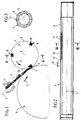
- FIG. 1 Schematically and partially shown in section in FIG. 1 a guide 1 for a ribbon or wick 2 of textile fibers, this guide being, in the preferred application of the invention, an outlet guide for a spinning preparation machine, for example a drawing bench, this guide 1 being driven in a rotation movement, continuous or alternative, about its longitudinal axis 3 to give the ribbon 2 a slight false twist at the exit, reinforcing its cohesion and its mechanical strength.
- This fiber ribbon 2 is intended to be wound or wound on a mandrel 4 driven in continuous rotation about its longitudinal axis 5, this rotation being indicated by the arrow A and being accompanied by an alternating axial displacement, as shown by the double arrow B (Fig. 2), to distribute the ribbon turns axially over the entire length of the mandrel 4.
- the mandrel 4 cooperates with a cylinder 6, called the winding cylinder, which rotates in the opposite direction to the mandrel 4, as shown by the arrow C, this winding cylinder being practically tangent to the mandrel 4, leaving a small space with it 7 in which the ribbon passes 2.
- the outlet guide 1 is arranged in the vicinity of the zone 7 of cooperation between the mandrel 4 and the take-up cylinder 6, and its longitudinal axis 3 is substantially tangent thereto.
- the ribbon 2 comes out substantially in a straight line from the guide 1, along the longitudinal axis 3 of the latter, to reach directly in the zone 7.
- the axis 3 is in fact not exactly tangent to the mandrel 4 and to the winding cylinder 6, but it is arranged in such a way that the ribbon 2 comes first to cooperate with the winding cylinder 6 which takes it in and deflects it slightly towards the mandrel 4.
- the peripheral surface 8 of the mandrel 4 has at least locally gripping properties with respect to the ribbon 2 to hang the front or upstream end 9 of the fiber ribbon 2 and thus cause the beginning of the winding or winding without the use is made of the folding device of the prior art previously discussed.
- these gripping properties, at least locally, of the peripheral surface 8 of the mandrel 4 can be obtained in various ways; for example, these hooking properties can be imparted by the surface condition of this peripheral surface 8 itself which will have undergone a mechanical or chemical treatment giving it, for example, a high roughness. It is also possible to use a rough strip which is attached to the peripheral surface 8 and which itself exhibits these gripping properties, for example being rough or adherent.
- the fastening elements are in slight radial projection towards the outside relative to the surface 8, so as not to cause a local excess thickness of the turns during winding.
- the gripping properties of the peripheral surface 8 of the mandrel 4 are only present over part of the length of this surface.
- the zone in which these hooking properties exist is then that on which the front end 9 of the ribbon 2 arrives.
- This local longitudinal limitation of the hooking properties is intended to prevent an excessive length of the ribbon 2 from being hooked and allow the subsequent unwinding of the mandrel 4 that only a short length of the tape 2 remains attached to the mandrel 4 and therefore risks being lost.
- the gripping properties of the peripheral surface 8 of the mandrel 4 are imparted by hooking elements which are in the form of at least one longitudinal strip. 10 of teeth 11, this strip being of the card lining type, the teeth 11 being for example metallic, To avoid excessive projection of the teeth 11, the strip 10 is housed in a longitudinal groove 12 of the mandrel 4.
- three strips 10 can be provided, arranged at 120 °.
- the front end 9 of the fiber ribbon 2, at the outlet of the guide 1, first reaches the peripheral surface of the take-up cylinder 6, then in the area 7 of cooperation between the mandrel 4 and the take-up cylinder 6 , to be quickly grasped by the peripheral surface 8 of the mandrel 4, thanks to the hanging properties described above of this surface 8, which causes the beginning of the winding of the ribbon 2 on the mandrel 4.
- the above device can advantageously be supplemented by pneumatic means (not shown), for example a nozzle projecting compressed air, for pressing the front end 9 of the ribbon 2 against the mandrel 4, before or after the zone 7 , or even in the zone 7 itself, to reinforce the attachment action of the mandrel 4 with respect to the fiber ribbon 2.
- pneumatic means for example a nozzle projecting compressed air, for pressing the front end 9 of the ribbon 2 against the mandrel 4, before or after the zone 7 , or even in the zone 7 itself, to reinforce the attachment action of the mandrel 4 with respect to the fiber ribbon 2.
- the device according to the invention is particularly simple, economical and reliable, thanks in particular to the fact that the folding member is eliminated, the drawbacks of which have been indicated above, and thanks to the fact that the ribbon 2 is directly supported by the mandrel 4 which is arranged to hook itself the front end of the ribbon.
Landscapes
- Engineering & Computer Science (AREA)
- Textile Engineering (AREA)
- Storage Of Web-Like Or Filamentary Materials (AREA)
- Replacement Of Web Rolls (AREA)
- Spinning Methods And Devices For Manufacturing Artificial Fibers (AREA)
Abstract
Description
- La présente invention est relative à un dispositif d'enroulement d'un ruban de fibres textiles sous la forme d'une bobine, en particulier dans le cas où ce ruban présente une cohésion et une résistance mécanique relativement faibles même si il a subi en amont une légère fausse torsion tendant à renforcer dans une certaine mesure ces deux dernières propriétés; tel est le cas par exemple d'un ruban de fibres qui est obtenu à la sortie d'une machine d'étirage, le ruban étant délivré à travers un guide de sortie qui lui imprime cette légère fausse torsion et qui le dirige vers le dispositif d'enroulement.
- Ce ruban étant mécaniquement fragile et susceptible de se dégrader en cas de sollicitation mécanique trop forte, on a jusqu'à présent fait appel,pour amorcer l'enroulement sur un mandrin de bobinage, à un organe rabatteur mobile dont le rôle était, au début du bobinage, de plaquer l'extrémité avant du ruban autour du mandrin pour que cette extrémité soit bien fixée sur ce dernier et que la formation de la bobine puisse, en principe, commencer et se poursuivre correctement. Toutefois, cette solution présente divers inconvénients : si le rabatteur n'a pas correctement rempli sa fonction, le début du bobinage est défectueux et toute la matière correspondante est perdue, ce qui représente une perte de matière et un abaissement du rendement de la machine, avec les répercussions économiques qui s'ensuivent; il arrive parfois que l'organe rabatteur effectue un mauvais enroulement pour les premières spires, celles-ci étant par exemple mal réparties ou emmêlées sur une seule zone, avec pour conséquences que soit les premières spires sont perdues, soit, si le bobinage se poursuit, la bobine est mal enroulée, avec les inconvénients qui en résultent lors de l'utilisation ultérieure de la bobine ; il arrive parfois que des enroulements intempestifs se produisent entre le cylindre enrouleur et le mandrin, ce cylindre enrouleur étant voisin du mandrin et guidant le ruban vers celui-ci ; l'organe rabatteur constitue une pièce mécanique commandée et il est donc susceptible de pannes et de mauvais fonctionnement, outre le fait qu'à lui seul, avec ses moyens de commande, il participe de manière non négligeable au prix de revient du dispositif d'enroulement.
- L'invention a pour but de remédier à ces inconvénients en fournissant un dispositif d'enroulement du genre indiqué ci-dessus qui ne fait pas appel à un organe rabatteur, tout en assurant un enroulement particulièrement fiable du ruban.
- A cet effet, le dispositif selon l'invention est caractérisé par le fait que la zone de coopération ou de convergence du mandrin et du cylindre enrouleur est située au voisinage de la sortie dudit guide pour recevoir directement le ruban et que la surface périphérique du mandrin présente au moins localement des propriétés accrochantes à l'égard du ruban.
- Suivant une réalisation préférée, le mandrin porte des éléments d'accrochage qui peuvent être constitués, par exemple, par au moins une bande longitudinale de dents, notamment du type garniture de carde, au moins une bande rugueuse adhérente, accrochante ou à aspérités rapportée sur ladite surface périphérique ; dans le cas d'au moins une bande de dents, celle-ci est logée dans une rainure longitudinale du mandrin ; par exemple, on peut prévoir trois bandes de dents disposées à 120°.
- Les propriétés accrochantes du mandrin à l'égard du ruban de fibres peuvent également être conférées par l'état de surface de ladite surface périphérique elle-même.
- Dans tous les cas, de préférence, les moyens conférant à la surface périphérique du mandrin ces propriétés accrochantes sont en faible saillie vers l'extérieur par rapport à cette surface.
- Dans la mesure où il s'agit surtout de saisir l'extrémité avant du ruban, les propriétés accrochantes de la surface périphérique du mandrin sont présentes au moins dans la zone longitudinale d'arrivée de cette extrémité avant du ruban.
- Le dispositif ci-dessus peut avantageusement être complété par des moyens pneumatiques, par exemple une buse, pour plaquer l'extrémité avant de ruban contre le mandrin et renforcer ainsi l'effet des propriétés accrochantes de la surface périphérique de ce dernier.
- On comprendra bien l'invention à la lecture du complément de description qui va suivre et en référence au dessin annexé qui fait partie de la description et dans lequel:
- Fig. 1 est une vue schématique et partielle en élévation d'un dispositif établi selon un mode de réalisation préféré de l'invention ;
- Fig. 2 est une coupe longitudinale du mandrin suivant la ligne II-II de la Fig. 1 ; et
- Fig. 3 est une coupe transversale suivant la ligne III-III du mandrin de la Fig. 2.
- On a schématiquement et partiellement représenté en coupe sur la Fig. 1 un guide 1 pour un ruban ou mèche 2 de fibres textiles, ce guide étant, dans l'application préférée de l'invention, un guide de sortie d'une machine de préparation à la filature, par exemple un banc d'étirage, ce guide 1 étant animé d'un mouvement de rotation, continue ou alternative, autour de son axe longitudinal 3 pour conférer en sortie au ruban 2 une légère fausse torsion renforçant sa cohésion et sa résistance mécanique.
- Ce ruban de fibres 2 est destiné à être enroulé ou bobiné sur un mandrin 4 entraîné en rotation continue autour de son axe longitudinal 5, cette rotation étant indiquée par la flèche A et étant accompagnée d'un déplacement axial alternatif, comme montré par la double flèche B (Fig. 2), pour répartir axialement les spires de ruban sur toute la longueur du mandrin 4.
- De façon connue, le mandrin 4 coopère avec un cylindre 6, dit cylindre enrouleur, qui tourne en sens inverse du mandrin 4, comme montré par la flèche C, ce cylindre enrouleur étant pratiquement tangent au mandrin 4 en ménageant avec lui un faible espace 7 dans lequel passe le ruban 2.
- Le guide de sortie 1 est disposé au voisinage de la zone 7 de coopération entre le mandrin 4 et le cylindre enrouleur 6, et son axe longitudinal 3 est sensiblement tangent à ceux-ci. Ainsi, le ruban 2 sort sensiblement en ligne droite du guide 1, suivant l'axe longitudinal 3 de celui-ci, pour parvenir directement dans la zone 7. Dans la pratique, l'axe 3 n'est en fait pas exactement tangent au mandrin 4 et au cylindre enrouleur 6, mais il est disposé de telle manière que le ruban 2 vienne d'abord coopérer avec le cylindre enrouleur 6 qui le prend en charge et le dévie légèrement vers le mandrin 4.
- La surface périphérique 8 du mandrin 4 présente au moins localement des propriétés accrochantes à l'égard du ruban 2 pour accrocher l'extrémité avant ou amont 9 du ruban de fibres 2 et provoquer ainsi le début de l'enroulement ou bobinage sans que l'on ait recours à l'organe rabatteur de l'art antérieur précédemment discuté.
- Ces propriétés accrochantes, au moins localement, de la surface périphérique 8 du mandrin 4 peuvent être obtenues de diverses manières; par exemple, ces propriétés accrochantes peuvent être conférées par l'état de surface de cette surface périphérique 8 elle-même qui aura subi un traitement mécanique ou chimique lui conférant par exemple une forte rugosité. On peut aussi faire appel à une bande rugueuse qui est rapportée sur la surface périphérique 8 et qui présente elle-même ces propriétés accrochantes, en étant par exemple rugueuse ou adhérente .
- Quelle que soit la manière dont on confère à la surface périphérique 8 du mandrin 4 ces propriétés accrochantes, les éléments d'accrochage, qu'ils soient rapportés ou qu'ils fassent partie intégrante de cette surface, sont en faible saillie radiale vers l'extérieur par rapport à la surface 8, de manière à ne pas provoquer une surépaisseur locale des spires lors de l'enroulement.
- De préférence, comme montré sur la Fig. 2, les propriétés accrochantes de la surface périphérique 8 du mandrin 4 ne sont présentes que sur une partie de la longueur de cette surface. La zone dans laquelle existent ces propriétés accrochantes est alors celle sur laquelle arrive l'extrémité avant 9 du ruban 2. tette limitation longitudinale locale des propriétés accrochantes a pour but d'éviter qu'une trop grande longueur du ruban 2 ne soit accrochée et de permettre au dévidage ultérieur du mandrin 4 qu'une faible longueur seulement du ruban 2 reste accrochée sur le mandrin 4 et risque par conséquent d'être perdue.
- Suivant le mode de réalisation préféré de l'invention, qui est représenté sur le dessin, les propriétés accrochantes de la surface périphérique 8 du mandrin 4 sont conférées par des éléments d'accrochage qui se présentent sous la forme d'au moins une bande longitudinale 10 de dents 11, cette bande étant du type garniture de carde, les dents 11 étant par exemple métalliques, Pour éviter une trop forte saillie des dents 11, la bande 10 est logée dans une rainure longitudinale 12 du mandrin 4.
- Par exemple, comme montré sur les Figs. 1 et 3, on peut prévoir trois bandes 10 disposées à 120 °.
- En fonctionnement, l'extrémité avant 9 du ruban de fibres 2, à la sortie du guide 1, parvient d'abord sur la surface périphérique du cylindre enrouleur 6, puis dans la zone 7 de coopération entre le mandrin 4 et le cylindre enrouleur 6, pour être rapidement saisie par la surface périphérique 8 du mandrin 4, grâce aux propriétés accrochantes ci-dessus décrites de cette surface 8, ce qui provoque le début de l'enroulement du ruban 2 sur le mandrin 4.
- Le dispositif ci-dessus peut avantageusement être complété par des moyens pneumatiques (non représentés), par exemple une buse projetant de l'air comprimé, pour plaquer l'extrémité avant 9 du ruban 2 contre le mandrin 4, avant ou après la zone 7, ou même dans la zone 7 elle-même, pour renforcer l'action d'accrochage du mandrin 4 à l'égard du ruban de fibres 2.
- Il ressort de la description ci-dessus que le dispositif selon l'invention est particulièrement simple, économique et fiable, grâce notamment au fait que l'on supprime l'organe rabatteur, dont on a indiqué précédemment les inconvénients, et grâce au fait que le ruban 2 est directement pris en charge par le mandrin 4 qui est agencé pour accrocher lui-même l'extrémité avant du ruban.
Claims (9)
- Dispositif d'enroulement en bobine d'un ruban de fibres textiles (2), ce dispositif étant situé à la sortie d'un guide (1) pour le ruban et comportant un mandrin (4) destiné à recevoir le ruban par enroulement de celui-ci et un cylindre enrouleur (6) voisin du mandrin (4) et destiné à diriger le ruban sur celui-ci, caractérisé par le fait que la zone (7) de coopération ou de convergence du mandrin (4) et du cylindre enrouleur (6) est située au voisinage de la sortie dudit guide (1) pour recevoir directement le ruban (2) et que la surface périphérique (8) du mandrin (4) présente au moins localement des propriétés accrochantes à l'égard du ruban (2).
- Dispositif selon la revendication 1, caractérisé par le fait que le mandrin (4) porte des éléments d'accrochage (11).
- Dispositif selon la revendication 2, caractérisé par le fait que les éléments d'accrochage appartiennent au groupe constitué par au moins une bande longitudinale (10) de dents, du type garniture de carde, au moins une bande rugueuse,adhérente,accrochante ou à aspérités rapportée sur ladite surface périphérique (8).
- Dispositif selon la revendication 3, caractérisé par le fait que la bande de dents est logée dans une rainure longitudinale (12) du mandrin (4).
- Dispositif selon l'une des revendications 3 et 4, caractérisé par le fait qu'il existe trois bandes de dents disposées à 120°.
- Dispositif selon l'une des revendications 1 à 5, caractérisé par le fait que les éléments accrochants sont en faible saillie radiale vers l'extérieur par rapport à la surface périphérique (8) du mandrin (4).
- Dispositif selon l'une des revendications 1 à 6, caractérisé par le fait que la surface périphérique (8) du mandrin (4) présente lesdites propriétés accrochantes au moins dans la zone longitudinale d'arrivée de l'extrémité avant (9) du ruban.
- Dispositif selon l'une des revendications 1,2,6 et 7, caractérisé par le fait que les propriétés accrochantes sont conférées par l'état de surface de la surface périphérique (8) du mandrin (4).
- Dispositif selon l'une des revendications 1 à 8, caractérisé par le fait qu'il comporte des moyens pneumatiques pour plaquer l'extrémité avant (9) du ruban (2) contre le mandrin (4).
Applications Claiming Priority (2)
| Application Number | Priority Date | Filing Date | Title |
|---|---|---|---|
| FR9108877A FR2679260A1 (fr) | 1991-07-15 | 1991-07-15 | Dispositif d'enroulement en bobine d'un ruban de fibres textiles. |
| FR9108877 | 1991-07-15 |
Publications (2)
| Publication Number | Publication Date |
|---|---|
| EP0524074A1 true EP0524074A1 (fr) | 1993-01-20 |
| EP0524074B1 EP0524074B1 (fr) | 1996-12-11 |
Family
ID=9415086
Family Applications (1)
| Application Number | Title | Priority Date | Filing Date |
|---|---|---|---|
| EP19920402008 Expired - Lifetime EP0524074B1 (fr) | 1991-07-15 | 1992-07-10 | Dispositif d'enroulement en bobine d'un ruban de fibres textiles |
Country Status (4)
| Country | Link |
|---|---|
| EP (1) | EP0524074B1 (fr) |
| DE (1) | DE69215780T2 (fr) |
| ES (1) | ES2094889T3 (fr) |
| FR (1) | FR2679260A1 (fr) |
Cited By (2)
| Publication number | Priority date | Publication date | Assignee | Title |
|---|---|---|---|---|
| WO1998055386A1 (fr) * | 1997-06-03 | 1998-12-10 | Kimberly-Clark Worldwide, Inc. | Bobine d'enroulement dotee d'un mecanisme d'entremelement integre |
| CN102766994A (zh) * | 2012-06-17 | 2012-11-07 | 淮北宇光纺织器材有限公司 | 盖板针布包覆机的动力控制装置 |
Citations (5)
| Publication number | Priority date | Publication date | Assignee | Title |
|---|---|---|---|---|
| US1484902A (en) * | 1923-06-28 | 1924-02-26 | George R Paige | Carding-machine condenser |
| GB1341034A (en) * | 1970-03-24 | 1973-12-19 | Tmm Research Ltd | Building of textile yarn packages |
| FR2217252A1 (fr) * | 1973-02-08 | 1974-09-06 | Murata Machinery Ltd | |
| FR2354024A7 (fr) * | 1976-06-04 | 1977-12-30 | Brovelli Loredana | Bobine pour l'enroulement de fils, pourvue de moyens de retenue du fil ou meche |
| GB2033342A (en) * | 1978-10-16 | 1980-05-21 | M Becker | Lap reel |
-
1991
- 1991-07-15 FR FR9108877A patent/FR2679260A1/fr active Granted
-
1992
- 1992-07-10 EP EP19920402008 patent/EP0524074B1/fr not_active Expired - Lifetime
- 1992-07-10 ES ES92402008T patent/ES2094889T3/es not_active Expired - Lifetime
- 1992-07-10 DE DE1992615780 patent/DE69215780T2/de not_active Expired - Fee Related
Patent Citations (5)
| Publication number | Priority date | Publication date | Assignee | Title |
|---|---|---|---|---|
| US1484902A (en) * | 1923-06-28 | 1924-02-26 | George R Paige | Carding-machine condenser |
| GB1341034A (en) * | 1970-03-24 | 1973-12-19 | Tmm Research Ltd | Building of textile yarn packages |
| FR2217252A1 (fr) * | 1973-02-08 | 1974-09-06 | Murata Machinery Ltd | |
| FR2354024A7 (fr) * | 1976-06-04 | 1977-12-30 | Brovelli Loredana | Bobine pour l'enroulement de fils, pourvue de moyens de retenue du fil ou meche |
| GB2033342A (en) * | 1978-10-16 | 1980-05-21 | M Becker | Lap reel |
Cited By (3)
| Publication number | Priority date | Publication date | Assignee | Title |
|---|---|---|---|---|
| WO1998055386A1 (fr) * | 1997-06-03 | 1998-12-10 | Kimberly-Clark Worldwide, Inc. | Bobine d'enroulement dotee d'un mecanisme d'entremelement integre |
| CN102766994A (zh) * | 2012-06-17 | 2012-11-07 | 淮北宇光纺织器材有限公司 | 盖板针布包覆机的动力控制装置 |
| CN102766994B (zh) * | 2012-06-17 | 2015-01-07 | 淮北宇光纺织器材有限公司 | 盖板针布包覆机的动力控制装置 |
Also Published As
| Publication number | Publication date |
|---|---|
| FR2679260A1 (fr) | 1993-01-22 |
| DE69215780T2 (de) | 1997-05-07 |
| DE69215780D1 (de) | 1997-01-23 |
| ES2094889T3 (es) | 1997-02-01 |
| EP0524074B1 (fr) | 1996-12-11 |
| FR2679260B1 (fr) | 1995-03-31 |
Similar Documents
| Publication | Publication Date | Title |
|---|---|---|
| EP0340101B1 (fr) | Cassette d'emmagasinage et de distribution de fil ou ruban sous tension préréglée, utilisable notamment sur une machine pour réaliser des pièces creuses par enroulement filamentaire | |
| CH462474A (fr) | Procédé de freinage d'un ruban métallique s'enroulant dans un cadre ou dans un boîtier d'instrument de mesures linéaires et instrument de mesures linéaires pour la mise en oeuvre de ce procédé | |
| JP3864040B2 (ja) | 梱包機におけるバンドリールのブレーキ構造 | |
| EP0524074B1 (fr) | Dispositif d'enroulement en bobine d'un ruban de fibres textiles | |
| FR2465806A1 (fr) | Procede et appareil pour le rattachement d'un fil enveloppe, en cas de cassure | |
| US4561600A (en) | Bobbin holder | |
| KR950030782A (ko) | 낚시용 스피닝 릴 | |
| CN215478763U (zh) | 缠胶带设备 | |
| EP0728117A1 (fr) | Procede de decalage des couches d'un bobinage | |
| KR101946676B1 (ko) | 권회장치 | |
| EP0091389B1 (fr) | Système lève-bobine de métier à dévider ou a retordre | |
| JPH07285214A (ja) | ブランケット装着方法及び装置 | |
| EP0088032B1 (fr) | Coronelle à couple résistant variable | |
| EP1940712B1 (fr) | Machine et procede de bobinage pour le stockage d'elements plats | |
| CN101395309A (zh) | 用于辊牵伸装置的输出辊的耐磨包覆物 | |
| EP0510735B1 (fr) | Prédélivreur de trame pour des métiers à tisser | |
| EP0253036B1 (fr) | Procédé et dispositif pour évacuer les mèches de déchets sur un métier à tisser | |
| FR2704003A1 (fr) | Dispositif pour la séparation du voile de fibres du cylindre peigneur dans une carde. | |
| CH590781A5 (en) | Wire twisting supply drum mounting - has supporting guide path to control tension of wire passing to twisting station | |
| BE1015203A5 (fr) | Dispositif de tension de fil et cantre mettant en oeuvre le dispositif. | |
| FR2500820A1 (fr) | Dispositif pour amorcer l'enroulement du fil sur un support de bobine dans les machines textiles equipees d'un systeme de bobinage | |
| EP0140796B1 (fr) | Procédé et dispositif pour la rattache de filés de fibres comportant une âme | |
| FR2485045A1 (fr) | Procede et metier pour la production de cassure volontaire de bande de fibres dans le filage par retordage de deux bandes de fibres | |
| FR2711128A1 (fr) | Bobine pour le conditionnement de câbles et fils de tous genres, et procédé de fabrication des flasques de ladite bobine. | |
| CH128957A (fr) | Procédé pour réaliser l'accrochage d'un brin textile alimenté de façon continue sur la bobine d'un métier continu à retordre à anneau et dispositif appliqué à un tel métier pour la mise en oeuvre du procédé. |
Legal Events
| Date | Code | Title | Description |
|---|---|---|---|
| PUAI | Public reference made under article 153(3) epc to a published international application that has entered the european phase |
Free format text: ORIGINAL CODE: 0009012 |
|
| AK | Designated contracting states |
Kind code of ref document: A1 Designated state(s): DE ES IT |
|
| 17P | Request for examination filed |
Effective date: 19930211 |
|
| 17Q | First examination report despatched |
Effective date: 19940823 |
|
| GRAG | Despatch of communication of intention to grant |
Free format text: ORIGINAL CODE: EPIDOS AGRA |
|
| GRAH | Despatch of communication of intention to grant a patent |
Free format text: ORIGINAL CODE: EPIDOS IGRA |
|
| GRAH | Despatch of communication of intention to grant a patent |
Free format text: ORIGINAL CODE: EPIDOS IGRA |
|
| GRAA | (expected) grant |
Free format text: ORIGINAL CODE: 0009210 |
|
| AK | Designated contracting states |
Kind code of ref document: B1 Designated state(s): DE ES IT |
|
| REF | Corresponds to: |
Ref document number: 69215780 Country of ref document: DE Date of ref document: 19970123 |
|
| REG | Reference to a national code |
Ref country code: ES Ref legal event code: FG2A Ref document number: 2094889 Country of ref document: ES Kind code of ref document: T3 |
|
| ITF | It: translation for a ep patent filed | ||
| PLBE | No opposition filed within time limit |
Free format text: ORIGINAL CODE: 0009261 |
|
| STAA | Information on the status of an ep patent application or granted ep patent |
Free format text: STATUS: NO OPPOSITION FILED WITHIN TIME LIMIT |
|
| 26N | No opposition filed | ||
| PGFP | Annual fee paid to national office [announced via postgrant information from national office to epo] |
Ref country code: ES Payment date: 19990701 Year of fee payment: 8 |
|
| PGFP | Annual fee paid to national office [announced via postgrant information from national office to epo] |
Ref country code: DE Payment date: 19990929 Year of fee payment: 8 |
|
| PG25 | Lapsed in a contracting state [announced via postgrant information from national office to epo] |
Ref country code: ES Free format text: LAPSE BECAUSE OF NON-PAYMENT OF DUE FEES Effective date: 20000711 |
|
| PG25 | Lapsed in a contracting state [announced via postgrant information from national office to epo] |
Ref country code: DE Free format text: LAPSE BECAUSE OF NON-PAYMENT OF DUE FEES Effective date: 20010501 |
|
| REG | Reference to a national code |
Ref country code: ES Ref legal event code: FD2A Effective date: 20010810 |
|
| PG25 | Lapsed in a contracting state [announced via postgrant information from national office to epo] |
Ref country code: IT Free format text: LAPSE BECAUSE OF NON-PAYMENT OF DUE FEES;WARNING: LAPSES OF ITALIAN PATENTS WITH EFFECTIVE DATE BEFORE 2007 MAY HAVE OCCURRED AT ANY TIME BEFORE 2007. THE CORRECT EFFECTIVE DATE MAY BE DIFFERENT FROM THE ONE RECORDED. Effective date: 20050710 |