EP0526111B1 - Automatisches Schallkontrollgerät - Google Patents
Automatisches Schallkontrollgerät Download PDFInfo
- Publication number
- EP0526111B1 EP0526111B1 EP92306756A EP92306756A EP0526111B1 EP 0526111 B1 EP0526111 B1 EP 0526111B1 EP 92306756 A EP92306756 A EP 92306756A EP 92306756 A EP92306756 A EP 92306756A EP 0526111 B1 EP0526111 B1 EP 0526111B1
- Authority
- EP
- European Patent Office
- Prior art keywords
- sound
- signal
- electric
- converter
- adaptive filtering
- Prior art date
- Legal status (The legal status is an assumption and is not a legal conclusion. Google has not performed a legal analysis and makes no representation as to the accuracy of the status listed.)
- Expired - Lifetime
Links
Images



Classifications
-
- F—MECHANICAL ENGINEERING; LIGHTING; HEATING; WEAPONS; BLASTING
- F01—MACHINES OR ENGINES IN GENERAL; ENGINE PLANTS IN GENERAL; STEAM ENGINES
- F01N—GAS-FLOW SILENCERS OR EXHAUST APPARATUS FOR MACHINES OR ENGINES IN GENERAL; GAS-FLOW SILENCERS OR EXHAUST APPARATUS FOR INTERNAL-COMBUSTION ENGINES
- F01N1/00—Silencing apparatus characterised by method of silencing
- F01N1/06—Silencing apparatus characterised by method of silencing by using interference effect
- F01N1/065—Silencing apparatus characterised by method of silencing by using interference effect by using an active noise source, e.g. speakers
-
- G—PHYSICS
- G10—MUSICAL INSTRUMENTS; ACOUSTICS
- G10K—SOUND-PRODUCING DEVICES; METHODS OR DEVICES FOR PROTECTING AGAINST, OR FOR DAMPING, NOISE OR OTHER ACOUSTIC WAVES IN GENERAL; ACOUSTICS NOT OTHERWISE PROVIDED FOR
- G10K11/00—Methods or devices for transmitting, conducting or directing sound in general; Methods or devices for protecting against, or for damping, noise or other acoustic waves in general
- G10K11/16—Methods or devices for protecting against, or for damping, noise or other acoustic waves in general
- G10K11/175—Methods or devices for protecting against, or for damping, noise or other acoustic waves in general using interference effects; Masking sound
- G10K11/178—Methods or devices for protecting against, or for damping, noise or other acoustic waves in general using interference effects; Masking sound by electro-acoustically regenerating the original acoustic waves in anti-phase
- G10K11/1781—Methods or devices for protecting against, or for damping, noise or other acoustic waves in general using interference effects; Masking sound by electro-acoustically regenerating the original acoustic waves in anti-phase characterised by the analysis of input or output signals, e.g. frequency range, modes, transfer functions
- G10K11/17821—Methods or devices for protecting against, or for damping, noise or other acoustic waves in general using interference effects; Masking sound by electro-acoustically regenerating the original acoustic waves in anti-phase characterised by the analysis of input or output signals, e.g. frequency range, modes, transfer functions characterised by the analysis of the input signals only
- G10K11/17823—Reference signals, e.g. ambient acoustic environment
-
- G—PHYSICS
- G10—MUSICAL INSTRUMENTS; ACOUSTICS
- G10K—SOUND-PRODUCING DEVICES; METHODS OR DEVICES FOR PROTECTING AGAINST, OR FOR DAMPING, NOISE OR OTHER ACOUSTIC WAVES IN GENERAL; ACOUSTICS NOT OTHERWISE PROVIDED FOR
- G10K11/00—Methods or devices for transmitting, conducting or directing sound in general; Methods or devices for protecting against, or for damping, noise or other acoustic waves in general
- G10K11/16—Methods or devices for protecting against, or for damping, noise or other acoustic waves in general
- G10K11/175—Methods or devices for protecting against, or for damping, noise or other acoustic waves in general using interference effects; Masking sound
- G10K11/178—Methods or devices for protecting against, or for damping, noise or other acoustic waves in general using interference effects; Masking sound by electro-acoustically regenerating the original acoustic waves in anti-phase
- G10K11/1783—Methods or devices for protecting against, or for damping, noise or other acoustic waves in general using interference effects; Masking sound by electro-acoustically regenerating the original acoustic waves in anti-phase handling or detecting of non-standard events or conditions, e.g. changing operating modes under specific operating conditions
-
- G—PHYSICS
- G10—MUSICAL INSTRUMENTS; ACOUSTICS
- G10K—SOUND-PRODUCING DEVICES; METHODS OR DEVICES FOR PROTECTING AGAINST, OR FOR DAMPING, NOISE OR OTHER ACOUSTIC WAVES IN GENERAL; ACOUSTICS NOT OTHERWISE PROVIDED FOR
- G10K11/00—Methods or devices for transmitting, conducting or directing sound in general; Methods or devices for protecting against, or for damping, noise or other acoustic waves in general
- G10K11/16—Methods or devices for protecting against, or for damping, noise or other acoustic waves in general
- G10K11/175—Methods or devices for protecting against, or for damping, noise or other acoustic waves in general using interference effects; Masking sound
- G10K11/178—Methods or devices for protecting against, or for damping, noise or other acoustic waves in general using interference effects; Masking sound by electro-acoustically regenerating the original acoustic waves in anti-phase
- G10K11/1785—Methods, e.g. algorithms; Devices
- G10K11/17853—Methods, e.g. algorithms; Devices of the filter
- G10K11/17854—Methods, e.g. algorithms; Devices of the filter the filter being an adaptive filter
-
- G—PHYSICS
- G10—MUSICAL INSTRUMENTS; ACOUSTICS
- G10K—SOUND-PRODUCING DEVICES; METHODS OR DEVICES FOR PROTECTING AGAINST, OR FOR DAMPING, NOISE OR OTHER ACOUSTIC WAVES IN GENERAL; ACOUSTICS NOT OTHERWISE PROVIDED FOR
- G10K11/00—Methods or devices for transmitting, conducting or directing sound in general; Methods or devices for protecting against, or for damping, noise or other acoustic waves in general
- G10K11/16—Methods or devices for protecting against, or for damping, noise or other acoustic waves in general
- G10K11/175—Methods or devices for protecting against, or for damping, noise or other acoustic waves in general using interference effects; Masking sound
- G10K11/178—Methods or devices for protecting against, or for damping, noise or other acoustic waves in general using interference effects; Masking sound by electro-acoustically regenerating the original acoustic waves in anti-phase
- G10K11/1787—General system configurations
- G10K11/17879—General system configurations using both a reference signal and an error signal
- G10K11/17883—General system configurations using both a reference signal and an error signal the reference signal being derived from a machine operating condition, e.g. engine RPM or vehicle speed
-
- G—PHYSICS
- G10—MUSICAL INSTRUMENTS; ACOUSTICS
- G10K—SOUND-PRODUCING DEVICES; METHODS OR DEVICES FOR PROTECTING AGAINST, OR FOR DAMPING, NOISE OR OTHER ACOUSTIC WAVES IN GENERAL; ACOUSTICS NOT OTHERWISE PROVIDED FOR
- G10K2210/00—Details of active noise control [ANC] covered by G10K11/178 but not provided for in any of its subgroups
- G10K2210/10—Applications
- G10K2210/128—Vehicles
-
- G—PHYSICS
- G10—MUSICAL INSTRUMENTS; ACOUSTICS
- G10K—SOUND-PRODUCING DEVICES; METHODS OR DEVICES FOR PROTECTING AGAINST, OR FOR DAMPING, NOISE OR OTHER ACOUSTIC WAVES IN GENERAL; ACOUSTICS NOT OTHERWISE PROVIDED FOR
- G10K2210/00—Details of active noise control [ANC] covered by G10K11/178 but not provided for in any of its subgroups
- G10K2210/10—Applications
- G10K2210/128—Vehicles
- G10K2210/1282—Automobiles
-
- G—PHYSICS
- G10—MUSICAL INSTRUMENTS; ACOUSTICS
- G10K—SOUND-PRODUCING DEVICES; METHODS OR DEVICES FOR PROTECTING AGAINST, OR FOR DAMPING, NOISE OR OTHER ACOUSTIC WAVES IN GENERAL; ACOUSTICS NOT OTHERWISE PROVIDED FOR
- G10K2210/00—Details of active noise control [ANC] covered by G10K11/178 but not provided for in any of its subgroups
- G10K2210/10—Applications
- G10K2210/128—Vehicles
- G10K2210/1282—Automobiles
- G10K2210/12822—Exhaust pipes or mufflers
-
- G—PHYSICS
- G10—MUSICAL INSTRUMENTS; ACOUSTICS
- G10K—SOUND-PRODUCING DEVICES; METHODS OR DEVICES FOR PROTECTING AGAINST, OR FOR DAMPING, NOISE OR OTHER ACOUSTIC WAVES IN GENERAL; ACOUSTICS NOT OTHERWISE PROVIDED FOR
- G10K2210/00—Details of active noise control [ANC] covered by G10K11/178 but not provided for in any of its subgroups
- G10K2210/30—Means
- G10K2210/301—Computational
- G10K2210/3026—Feedback
-
- G—PHYSICS
- G10—MUSICAL INSTRUMENTS; ACOUSTICS
- G10K—SOUND-PRODUCING DEVICES; METHODS OR DEVICES FOR PROTECTING AGAINST, OR FOR DAMPING, NOISE OR OTHER ACOUSTIC WAVES IN GENERAL; ACOUSTICS NOT OTHERWISE PROVIDED FOR
- G10K2210/00—Details of active noise control [ANC] covered by G10K11/178 but not provided for in any of its subgroups
- G10K2210/30—Means
- G10K2210/301—Computational
- G10K2210/3027—Feedforward
-
- G—PHYSICS
- G10—MUSICAL INSTRUMENTS; ACOUSTICS
- G10K—SOUND-PRODUCING DEVICES; METHODS OR DEVICES FOR PROTECTING AGAINST, OR FOR DAMPING, NOISE OR OTHER ACOUSTIC WAVES IN GENERAL; ACOUSTICS NOT OTHERWISE PROVIDED FOR
- G10K2210/00—Details of active noise control [ANC] covered by G10K11/178 but not provided for in any of its subgroups
- G10K2210/30—Means
- G10K2210/301—Computational
- G10K2210/3032—Harmonics or sub-harmonics
-
- G—PHYSICS
- G10—MUSICAL INSTRUMENTS; ACOUSTICS
- G10K—SOUND-PRODUCING DEVICES; METHODS OR DEVICES FOR PROTECTING AGAINST, OR FOR DAMPING, NOISE OR OTHER ACOUSTIC WAVES IN GENERAL; ACOUSTICS NOT OTHERWISE PROVIDED FOR
- G10K2210/00—Details of active noise control [ANC] covered by G10K11/178 but not provided for in any of its subgroups
- G10K2210/30—Means
- G10K2210/301—Computational
- G10K2210/3033—Information contained in memory, e.g. stored signals or transfer functions
-
- G—PHYSICS
- G10—MUSICAL INSTRUMENTS; ACOUSTICS
- G10K—SOUND-PRODUCING DEVICES; METHODS OR DEVICES FOR PROTECTING AGAINST, OR FOR DAMPING, NOISE OR OTHER ACOUSTIC WAVES IN GENERAL; ACOUSTICS NOT OTHERWISE PROVIDED FOR
- G10K2210/00—Details of active noise control [ANC] covered by G10K11/178 but not provided for in any of its subgroups
- G10K2210/30—Means
- G10K2210/301—Computational
- G10K2210/3039—Nonlinear, e.g. clipping, numerical truncation, thresholding or variable input and output gain
-
- G—PHYSICS
- G10—MUSICAL INSTRUMENTS; ACOUSTICS
- G10K—SOUND-PRODUCING DEVICES; METHODS OR DEVICES FOR PROTECTING AGAINST, OR FOR DAMPING, NOISE OR OTHER ACOUSTIC WAVES IN GENERAL; ACOUSTICS NOT OTHERWISE PROVIDED FOR
- G10K2210/00—Details of active noise control [ANC] covered by G10K11/178 but not provided for in any of its subgroups
- G10K2210/30—Means
- G10K2210/301—Computational
- G10K2210/3039—Nonlinear, e.g. clipping, numerical truncation, thresholding or variable input and output gain
- G10K2210/30391—Resetting of the filter parameters or changing the algorithm according to prevailing conditions
-
- G—PHYSICS
- G10—MUSICAL INSTRUMENTS; ACOUSTICS
- G10K—SOUND-PRODUCING DEVICES; METHODS OR DEVICES FOR PROTECTING AGAINST, OR FOR DAMPING, NOISE OR OTHER ACOUSTIC WAVES IN GENERAL; ACOUSTICS NOT OTHERWISE PROVIDED FOR
- G10K2210/00—Details of active noise control [ANC] covered by G10K11/178 but not provided for in any of its subgroups
- G10K2210/30—Means
- G10K2210/301—Computational
- G10K2210/3041—Offline
-
- G—PHYSICS
- G10—MUSICAL INSTRUMENTS; ACOUSTICS
- G10K—SOUND-PRODUCING DEVICES; METHODS OR DEVICES FOR PROTECTING AGAINST, OR FOR DAMPING, NOISE OR OTHER ACOUSTIC WAVES IN GENERAL; ACOUSTICS NOT OTHERWISE PROVIDED FOR
- G10K2210/00—Details of active noise control [ANC] covered by G10K11/178 but not provided for in any of its subgroups
- G10K2210/30—Means
- G10K2210/301—Computational
- G10K2210/3042—Parallel processing
-
- G—PHYSICS
- G10—MUSICAL INSTRUMENTS; ACOUSTICS
- G10K—SOUND-PRODUCING DEVICES; METHODS OR DEVICES FOR PROTECTING AGAINST, OR FOR DAMPING, NOISE OR OTHER ACOUSTIC WAVES IN GENERAL; ACOUSTICS NOT OTHERWISE PROVIDED FOR
- G10K2210/00—Details of active noise control [ANC] covered by G10K11/178 but not provided for in any of its subgroups
- G10K2210/30—Means
- G10K2210/301—Computational
- G10K2210/3045—Multiple acoustic inputs, single acoustic output
-
- G—PHYSICS
- G10—MUSICAL INSTRUMENTS; ACOUSTICS
- G10K—SOUND-PRODUCING DEVICES; METHODS OR DEVICES FOR PROTECTING AGAINST, OR FOR DAMPING, NOISE OR OTHER ACOUSTIC WAVES IN GENERAL; ACOUSTICS NOT OTHERWISE PROVIDED FOR
- G10K2210/00—Details of active noise control [ANC] covered by G10K11/178 but not provided for in any of its subgroups
- G10K2210/50—Miscellaneous
- G10K2210/501—Acceleration, e.g. for accelerometers
-
- G—PHYSICS
- G10—MUSICAL INSTRUMENTS; ACOUSTICS
- G10K—SOUND-PRODUCING DEVICES; METHODS OR DEVICES FOR PROTECTING AGAINST, OR FOR DAMPING, NOISE OR OTHER ACOUSTIC WAVES IN GENERAL; ACOUSTICS NOT OTHERWISE PROVIDED FOR
- G10K2210/00—Details of active noise control [ANC] covered by G10K11/178 but not provided for in any of its subgroups
- G10K2210/50—Miscellaneous
- G10K2210/503—Diagnostics; Stability; Alarms; Failsafe
Definitions
- the present invention relates to an automatic sound controlling apparatus outputting a signal with an opposite phase and an equivalent sound pressure to cancel the sound emitted from an engine etc..
- this invention enables an adaptive filtering means used in the apparatus to follow the sharp attenation of a sound frequency and thereby improve the accuracy of producing the canceling sound.
- a passive canceling apparatus such as a muffler etc.
- an active automatic sound controlling apparatus canceling a sound has output a compensating sound with an opposite phase and equivalent sound pressure from a sound source, but the frequency characteristics and stability etc. of this active automatic sound controlling apparatus per se are not sufficient, so realistic use thereof has diminished.
- a 1 microphone / 1 speaker set is provided as only the feedback of the prior art, however, an the case that the sound period of a sound source changes sharply, a problem arises in that the canceling effect is reduced since the signal delays more than the sound transfer characteristics at least from the microphone to the speaker, and is a defect of the feedback system.
- the conventional automatic sound controlling apparatus is installed in automobiles etc. although it is difficult to provide a microphone to receive the sound as explained above, it is possible to form a sound simulating signal from an engine rotation number.
- this signal is separate from a realistic signal although there is a quick response because of the signal of a feedforward system.
- a signal from a microphone as a feedback system which is a difference signal between a muffler and a speaker, is added to a signal with an opposite phase and the equivalent sound pressure is obtained by said signal processing circuit so that it is possible to form a sound reproducing signal.
- the present invention resolves the above-mentioned problem and provides an automatic sound controlling apparatus following the sharp change of a sound period and forming a signal that is similar to a realistic signal and superior to a response.
- an automatic sound controlling apparatus including an electric signal/sound converter outputting a compensating sound to a canceling object space to cancel a sound from a sound producing source and a sound/electric converter for converting a residual sound of the sound canceling with a compensating signal from the electric/sound converter into an electric signal to form an error signal owing to the residual sound, characterized in that it comprises:
- an automatic sound controlling apparatus including an electric signal/sound converter outputting a compensating sound to a canceling object space to cancel a sound from a sound producing source and a sound/electric converter for converting a residual sound of the canceling with a compensating signal from the electric/sound converter into an electric signal to form an error signal due to the residual sound, characterized in that it comprises:
- an automatic sound controlling apparatus may include additionally, a harmonic wave producing means that produces a harmonic wave signal of the sound based on the signal showing the rotation number of the engine or the signal showing the ignition timing.
- an automatic sound controlling apparatus including an electric signal/sound converter outputting a compensating sound to a canceling object space to cancel a sound from a sound producing source and a sound/electric converter for converting a residual sound of the sound canceling with a compensating signal from the electric/sound converter into an electric signal to form an error signal owing to the residual sound, characterised in that it comprises:
- the signal showing the rotation number or the signal showing the ignition timing of the engine is output to the adaptive filtering means by the switch.
- the controlling signal by these signals or the harmonic wave signal is small in the time delay to be formed so that the error owing to the time delay is small.
- the output of the adding means is output to the adaptive filtering by the switch, but at this time even when stepping on the accelerator the rotation number does not increase sharply for the adding load as described above so that the time delay is allowed and the output signal to the adaptive filtering means is as realistic as possible and small in error.
- the time of driving when the rotation number changes sharply, the signal showing the rotation number of the engine or the ignition timing of the engine or the output of the harmonic wave producing means is provided to prevent the time delay.
- the realistic signal is provided from the adding means to improve the accuracy of the apparatus as a whole.
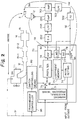
- Fig. 1 and 2 are views of an automatic sound controlling apparatus according to first and second embodiments of the present invention. Fig. 1 and 2 are different in the point concerning whether or not a harmonic wave producing means 7 is provided. Referring to Fig. 1 and 2, overall constructions of the apparatus will be discussed.
- a controlled object of the apparatus includes an engine 11 of an automobile, an exhaust pipe 12 for discharging exhaust gas of the engine 1 in the atmosphere, submufflers 13-1 and 13-2 in which the pressure of the exhaust gas is reduced gradually in the exhaust pipe to restrain sound production before the exhaust gas is discharged in the atmosphere and a sound owing to the reduced exhaust gas is reflected by a wall of the exhaust pipe, the reflected sounds interfer with each other and are canceled, a main muffler 14 following the submufflers 13-1 and 13-2 with the same object as above, a tail pipe 15 connected to the main muffler 14 to discharge the exhaust gas in the atmosphere.
- the apparatus includes a compensating signal producing means 70 for producing a controlled signal with regard to a sound of a feedforward system based on the rotation number of the engine 1 to form a compensating signal, a digital to analog converter 202 for converting a digital signal from the compensating signal producing means 70 into an analog signal, a low pass filter 203 connected to the digital to analog converter 202 to remove a harmonic wave signal, a power amplifier 201 connected to the low pass filter 203, a speaker 3 driven by a sound from the power amplifier 201 to discharge a sound and cancel a sound from the tail pipe, a microphone 3 that catches the result of canceling the sound from the tail pipe with the speaker 3 to convert an electric signal, an amplifier 301 connected to the microphone 3, a low pass filter 303 connected to the amplifier 301, an analog to digital converter 302 connected to the low pass filter 303 to convert same into an analog signal into a digital signal so that the converted signal is used as feedback control and controlled signals of the compensating signal producing means 70, a switch controlling means 80 that inputs
- the compensating signal producing means 70 includes a prefilter 72 for equalizing the frequency characteristics of the submufflers 13-1, 13-2 and the main muffler 14 in advance, a coefficient memory 73 for providing the prefilter 72 with a coefficient, an initial setting circuit 74 for setting the measured coefficient of the submuffler 13-1, 13-2 and the main muffler 14 to the coefficient memory 73 from outside, a switch 75 provided at the input side of the prefilter 72, one terminal (a) of which inputs a signal showing the rotation number or a signal showing the ignition timing Sr as a feedforward signal, the other terminal (b) of which inputs a feedback signal as explained herebelow, and these two terminals of which are switched by the switch controlling means 80, an adaptive filtering means 76 that inputs a signal from the prefilter 72 as a controlled signal and outputs a compensating signal to the digital to analog converter 202, a minimization means 77 that sets the coefficient to the adaptive filter means 76 to minimize an error signal from the
- the signal showing the rotation number of the engine 1 is taken out from a sensor fitted to a rotary axis such as a crankshaft, also the signal showing the ignition timing is taken out from, for example, a distributor.
- a harmonic wave producing means 71 in which a signal Sr showing the rotation number of the engine 1 or a signal Sr showing the ignition timing of the engine is used as a fundamental signal so that these harmonic wave signals are produced, is provided to input a signal of the harmonic wave signal producing means 71 to the one terminal of the switch 75.
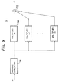
- Fig. 3 is a view showing the construction of a harmonic producer in Fig. 2.
- the harmonic wave signal producing means 71 includes a variable frequency oscillator 711 that forms a sound with a frequency corresponding to the rotation number or the ignition timing of the engine 1, a plurality of multipliers 712 for multiplying the frequency of the output of the variable frequency oscillator 711, and an adder means 713 for adding the outputs of a plurality of multipliers 712 to output the added signal to the prefilter 72.
- Fig. 4 is a view showing the relation between the engine rotation number and the sound frequency in a variable frequency oscillator of Fig. 3.
- the sound source of the engine 1 is an assembly of harmonic components such as the first order, the second order, the third order, ⁇ , the nth order depending on the rotation number, and the harmonic components increase together with the rotation number increment.
- the variable frequency oscillator 711 shown in Fig. 3 in order to produce the above sound, the rotation number of the engine 1 and the sound frequency from the tail pipe are measured in advance to obtain the relation as shown in this Figure and the signal with the frequency corresponding to the rotation number of the engine 1 is produced to output it to the following multipliers 712.
- the harmonic components included in the produced sound of the engine 1 are made with high accuracy, and since pulse shapes showing the rotation number of the engine 1 partly includes the harmonic wave signal, by using the pulse shape directly, the same effect as above may be expected to some degree.
- the signal showing ignition timing is normally a signal that multiplies the signal showing the rotation number.
- Fig. 5 is a view showing the construction of a prefilter and an adaptive filter in Fig. 1 and 2.
- the prefilter 72 and the adaptive filtering means 76 are common in construction but different in setting a coefficient.
- Both the prefilter 72 and the adaptive filtering means 76 include a plurality of delay devices 721 delaying an input signal every sampling period, a plurality of variable multipliers 722 that accept the input signal and are connected to the output of each of the delay devices, a plurality of adding means 723 connected to each of the variable multipliers 722.
- Coefficients a0, a1, a2, ⁇ , am of each of the variable multipliers are variable owing to being supplied by the coefficient memory 73 and the minimization means 77.
- sampling frequency be fs
- T 1/fs
- the frequency characteristics of the submufller 13-1, 13-2 and the main muffler 14 are measured in advance so that on the basis of this measurement the coefficients a0, a1, a2, ⁇ ,am of each of the variable multipliers 722 in the above equation are set to the initial setting circuit 74 and the coefficient memory 73.
- ak(n+1) ak(n)+ ⁇ ⁇ e(n) ⁇ x(n-k)/
- x(n-i) 2 ⁇ x(n) 2 +x(n-1) 2 +x(n-2) 2 + ⁇ +x(n-m) 2 ⁇ /m
- Equation e(n) shows an error signal that is an output signal of the analog to digital converter 302 and ⁇ shows a convergence constant. It takes a predetermined time to cause the coefficient ak(n) to converge at a constant. Accordingly, as explained above an influence of the main muffler 4 etc. is removed from the adaptive filtering means 76 to reduce the load of the adaptive filtering 76, while since a constant convergence time is needed, it would be difficult to process within the convergence time when the change of the rotation number of the engine 1 is large.
- the producing signal SR of the feedback system input to the other terminal of the switch 75 will be discussed.
- the sound signal produced by the engine 1 be SN
- the output signal be SC
- the output of the microphone 3 be SM
- the output of the adding means 79 be SR.
- the transfer characteristics from the engine 1 to the microphone 3 be HNOISE
- the transfer characteristics from the adaptive filtering 76 to the microphone 3 be Hd1
- Hd Hd1 ⁇ HM
- the output signal SM of the microphone 3 is expressed as follows.
- SM SN ⁇ HNOISE + SC ⁇ Hd1
- the output signal of the adding means SR is expressed as follows.
- ⁇ HM SN ⁇ HNOISE ⁇ HM Therefore a signal obtained when only a sound is detected by the microphone 3 may be calculated.
- the output signal SE of the analog to digital converter 302 is given as a control signal for making the coefficient renewal by the minimization means 77 of the adaptive filtering means 76.
- Fig. 6 is a view explaining the operation of switching a switch 75 in Fig. 1 and 2.
- the switch controlling means 80 obtaining the transmission shift position signal from the transmission controller 90 makes the switch 75 connect to the switch terminal (a) side when the transmission shift position is in a no load state such as P range for parking or N range for neutral as shown in this Figure.
- the switch 75 is connected to the output (switch terminal b side) of the adding means 79. Therefore when in a no load state, the adaptive filtering means 76 inputs a controlled signal of the feedforward system, and when in a load state, it inputs a controlled signal of the feed back system.
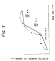
- Fig. 7 is a view explaining the operation of switching a switch 75 in Fig. 2 depending on the change of the engine rotation number.
- the switch controlling means 80 shown in Fig. 1 and 2 obtains a change of the rotation of the engine 1 as dSr/dt as shown in Fig. 7
- the adaptive filtering means 76 is connected to the switch terminal (a) side by the switch 75.
- the switch terminal is connected to (a) side by the switch 75 to connect the adaptive filtering means to the adding means 79.
- the adaptive filtering means 76 inputs the controlled signal of the feedback system and uses the realistic signal to improve accuracy thereof. Further in return [compensation] for not allowing a processing delay when velocity changes, the adaptive filtering means 76 inputs a signal somewhat apart from the realistic signal, but if the change of the sound is large it is possible to improve accuracy with a short delay controlling signal.
- the switch 75 when the switch 75 is connected to the terminal (a) side, and when the convergence constant ⁇ is larger, the convergence as expressed above becomes faster and the delay time becomes shorter. On the contrary when the switch 75 is connected to the terminal (b) side it is possible to take a slow convergence in order to improve the accuracy when the velocity does not change.
- either of the switching controls of the switch 75 by the position of the transmission and by the change of the rotation number of the engine 1 may be performed individually.
- the transmission controlling means 90 may provide the position of the shift lever so that it may output a signal showing the position of the transmission and is not especially limited to the automatic transmission.
- an automatic sound controlling apparatus including an adaptive filter that makes the coefficient renewal minimize the error signal to form the opposite characteristics of the sound
- a signal with a short delay but somewhat unrealistic is used as a control signal
- a signal with a somewhat large delay but realistic is used as a control signal so that it is possible to improve the accuracy of the adaptive filtering means.
Landscapes
- Engineering & Computer Science (AREA)
- Physics & Mathematics (AREA)
- Acoustics & Sound (AREA)
- Multimedia (AREA)
- Chemical & Material Sciences (AREA)
- Combustion & Propulsion (AREA)
- Mechanical Engineering (AREA)
- General Engineering & Computer Science (AREA)
- Soundproofing, Sound Blocking, And Sound Damping (AREA)
- Exhaust Silencers (AREA)
- Control Of Amplification And Gain Control (AREA)
Claims (3)
- Automatische Tonregelvorrichtung mit einem Elektrosignal-/Tonwandler (2), der einen kompensierenden Ton an einen Löschobjektraum aussendet, um einen Ton von einer tonerzeugenden Quelle (1) zu löschen, und einem Ton-/Elektrowandler (3), um einen Restton der Tonlöschung mit einem Kompensationssignal vom Elektro-/Tonwandler (2) in ein elektrisches Signal umzuwandeln, um ein Fehlersignal in Abhängigkeit vom Restton zu bilden, dadurch gekennzeichnet, daß sie umfaßt:ein adaptives Filtermittel (76), welches Filterkoeffizienten auf der Grundlage des Fehlersignals vom Ton-/Elektrowandler (3) regelt, um ein kompensierendes Signal für den Elektro-/Tonwandler (2) zu bilden, um einen stationären Ton zu löschen,ein Transfercharakteristiksimulationsmittel (78), das an einen Ausgang des adaptiven Filtermittels (76) angeschlossen ist und die Transfercharakteristik vom adaptiven Filtermittel (76) durch den Elektrosignal-/Tonwandler (2) und den Ton-/Elektrowandler (3) zu einem Ausgang des Transfercharakteristiksimulationsmittels (78) simuliert, um ein Eingangssignal des adaptiven Filtermittels (76) durch Addieren eines Ausgangssignals des Transfercharakteristiksimulationsmittels (78) und des Fehlersignals vom Ton-/Elektrowandler (3) zu bilden,ein Additionsmittel (79), welches das Fehlersignal und ein umgekehrtes Ausgangssignal des Transfercharakteristiksimulationsmittels (78) addiert,einen Schalter (75), der alternativ ein Signal auswählt, welches die Umdrehungsgeschwindigkeit eines Motors zeigt, ein Signal, welches den Zündzeitpunkt des Motors zeigt, oder einen Ausgang des Additionsmittels (79) als Eingangssignal des adaptiven Filtermittels (76), undwenn sich die Position der Motorübertragung in einem Null-Last-Zustand des Motors befindet, der Schalter (75) dem adaptiven Filtermittel (76) das Signal liefert, welches die Umdrehungsgeschwindigkeit des Motors zeigt, oder das Signal, welches den Zündzeitpunkt zeigt, oder wenn sich die Übertragungsposition in einem Last-Zustand des Motors befindet, der Schalter (75) dem adaptiven Filtermittel (76) den Ausgang des Additionsmittels (79) liefert.
- Automatische Tonregelvorrichtung mit einem Elektrosignal-/Tonwandler (2), der einen kompensierenden Ton an einen Löschobjektraum aussendet, um einen Ton von einer tonerzeugenden Quelle (1) zu löschen, und einem Ton-/Elektrowandler (3), um einen Restton der Löschung mit einem Kompensationssignal vom Elektro-/Tonwandler (2) in ein elektrisches Signal umzuwandeln, um ein Fehlersignal in Abhängigkeit vom Restton zu bilden, dadurch gekennzeichnet, daß sie umfaßt:ein adaptives Filtermittel (76), welches die Filterkoeffizienten auf der Grundlage eines Fehlersignals regelt, das vom Ton-/Elektrowandler (3) gesendet wird, um ein kompensierendes Signal für den Elektro-/Tonwandler (2) zu bilden, um einen stationären Ton zu löschen,ein Transfercharakteristiksimulationsmittel (78), das an einen Ausgang des adaptiven Filtermittels (76) angeschlossen ist und die Transfercharakteristik vom adaptiven Filtermittel (76) durch den Elektrosignal-/Tonwandler (2) und den Ton-/Elektrowandler (3) zu einem Ausgang des Transfercharakteristiksimulationsmittels (78) simuliert, um ein Eingangssignal des adaptiven Filtermittels (76) durch Addieren eines Ausgangssignals des Transfercharakteristiksimulationsmittels (78) und des Fehlersignals vom Ton-/Elektrowandler (3) zu bilden,ein Additionsmittel (79), welches das Fehlersignal und ein umgekehrtes Ausgangssignal des Transfercharakteristiksimulationsmittels (78) addiert,einen Schalter (75), der alternativ ein Signal auswählt, welches die Umdrehungsgeschwindigkeit eines Motors zeigt, ein Signal, welches den Zündzeitpunkt des Motors zeigt, oder einen Ausgang des Additionsmittels (79) als Eingangssignal des adaptiven Filtermittels (76), undwenn eine Änderung der Umdrehungsgeschwindigkeit des Motors größer ist als ein vorherbestimmter Wert, der Schalter (75) dem adaptiven Filtermittel (76) das Signal liefert, das die Umdrehungsgeschwindigkeit des Motors anzeigt, oder das Signal, das den Zündzeitpunkt anzeigt, und wenn die Änderung der Umdrehungsgeschwindigkeit des Motors kleiner ist als der vorherbestimmte Wert, der Schalter (75) dem adaptiven Filtermittel (76) das Ausgangssignal des Additionsmittels (79) liefert.
- Automatische Tonregelvorrichtung mit einem Elektrosignal-/Tonwandler (2), der einen kompensierenden Ton an einen Löschobjektraum aussendet, um einen Ton von einer tonerzeugenden Quelle (1) zu löschen, und einem Ton-/Elektrowandler (3), um einen Restton der Tonlöschung mit einem Kompensationssignal vom Elektro-/Tonwandler (2) in ein elektrisches Signal zu wandeln, um ein Fehlersignal in Abhängigkeit vom Restton zu bilden, dadurch gekennzeichnet, daß sie umfaßt:ein adaptives Filtermittel (76), welches die Filterkoeffizienten auf der Grundlage des Fehlersignals regelt, das vom Ton-/Elektrowandler (3) gesendet wird, um ein kompensierendes Signal für den Elektro-/Tonwandler (2) zu bilden, um einen stationären Ton zu löschen,ein Transfercharakteristiksimulationsmittel (78), das an einen Ausgang des adaptiven Filtermittels (76) angeschlossen ist und die Transfercharakteristik vom adaptiven Filtermittel (76) durch den Elektrosignal-/Tonwandler (2) und den Ton-/Elektrowandler (3) zu einem Ausgang des Transfercharakteristiksimulationsmittels (78) simuliert, um ein Eingangssignal des adaptiven Filtermittels (76) durch Addieren eines Ausgangssignals des Transfercharakteristiksimulationsmittels (78) und des Fehlersignals vom Ton-/Elektrowandler (3) zu bilden,ein harmonische Wellen erzeugendes Mittel (71), das ein harmonisches Wellensignal des Tons basierend auf dem Signal erzeugt, welches die Umdrehungsgeschwindigkeit eines Motors anzeigt, oder dem Signal, welches den Zündzeitpunkt anzeigt,ein Additionsmittel (79), welches das Fehlersignal und ein umgekehrtes Ausgangssignal des Transfercharakteristiksimulationsmittels (78) addiert,einen Schalter (75), der alternativ ein Signal auswählt, welches die Umdrehungsgeschwindigkeit eines Motors zeigt, ein Signal, welches den Zündzeitpunkt des Motors zeigt, oder einen Ausgang des Additionsmittels (79) als Eingangssignal des adaptiven Filtermittels (76), undwenn eine Änderung der Umdrehungsgeschwindigkeit des Motors größer ist als ein vorherbestimmter Wert, der Schalter (75) dem adaptiven Filtermittel (76) das harmonische Wellensignal liefert, das vom harmonische Wellen erzeugenden Mittel (71) erzeugt wird, oder das Signal, das den Zündzeitpunkt anzeigt, und wenn die Änderung der Umdrehungsgeschwindigkeit des Motors kleiner ist als der vorherbestimmte Wert, der Schalter (75) dem adaptiven Filtermittel (76) das Ausgangssignal des Additionsmittels (79) liefert.
Applications Claiming Priority (6)
| Application Number | Priority Date | Filing Date | Title |
|---|---|---|---|
| JP191902/91 | 1991-07-31 | ||
| JP3191902A JP2935592B2 (ja) | 1991-07-31 | 1991-07-31 | 騒音制御装置 |
| JP19190291 | 1991-07-31 | ||
| JP28641791 | 1991-10-31 | ||
| JP286417/91 | 1991-10-31 | ||
| JP28641791A JP3506442B2 (ja) | 1991-10-31 | 1991-10-31 | 騒音制御装置 |
Publications (3)
| Publication Number | Publication Date |
|---|---|
| EP0526111A2 EP0526111A2 (de) | 1993-02-03 |
| EP0526111A3 EP0526111A3 (en) | 1994-06-08 |
| EP0526111B1 true EP0526111B1 (de) | 2000-02-16 |
Family
ID=26506974
Family Applications (1)
| Application Number | Title | Priority Date | Filing Date |
|---|---|---|---|
| EP92306756A Expired - Lifetime EP0526111B1 (de) | 1991-07-31 | 1992-07-23 | Automatisches Schallkontrollgerät |
Country Status (4)
| Country | Link |
|---|---|
| US (2) | US5404409A (de) |
| EP (1) | EP0526111B1 (de) |
| CA (1) | CA2074295C (de) |
| DE (1) | DE69230681T2 (de) |
Families Citing this family (20)
| Publication number | Priority date | Publication date | Assignee | Title |
|---|---|---|---|---|
| US5404409A (en) * | 1991-07-31 | 1995-04-04 | Fujitsu Ten Limited | Adaptive filtering means for an automatic sound controlling apparatus |
| JP2856625B2 (ja) * | 1993-03-17 | 1999-02-10 | 株式会社東芝 | 適応形能動消音装置 |
| US5633795A (en) * | 1995-01-06 | 1997-05-27 | Digisonix, Inc. | Adaptive tonal control system with constrained output and adaptation |
| US6078672A (en) * | 1997-05-06 | 2000-06-20 | Virginia Tech Intellectual Properties, Inc. | Adaptive personal active noise system |
| US6094601A (en) * | 1997-10-01 | 2000-07-25 | Digisonix, Inc. | Adaptive control system with efficiently constrained adaptation |
| JPH11118273A (ja) * | 1997-10-16 | 1999-04-30 | Fujitsu Ltd | 騒音低減機能付き音響冷却装置 |
| US6949528B1 (en) * | 1998-03-18 | 2005-09-27 | Goddard John G | Compositions containing lysophosphatidic acids which inhibit apoptosis and uses thereof |
| US6665337B1 (en) * | 1999-03-31 | 2003-12-16 | Intel Corporation | Activation method in data transceivers |
| US20030079937A1 (en) * | 2001-10-30 | 2003-05-01 | Siemens Vdo Automotive, Inc. | Active noise cancellation using frequency response control |
| US20030152216A1 (en) * | 2002-01-14 | 2003-08-14 | Manish Vaishya | Acoustic enhancement of frequencies with large amplitude variation in an active noise cancellation system |
| EP1630788B1 (de) * | 2004-08-26 | 2012-04-18 | Airbus Operations GmbH | Vorrichtung und Verfahren zur Reduktion von Schall einer Rauschquelle in beschränkten Frequenzbereichen |
| US20070125592A1 (en) * | 2005-12-07 | 2007-06-07 | Frank Michell | Excitation of air directing valves and air handling surfaces in the cancellation of air handling system noise |
| DE102006059351A1 (de) * | 2006-12-15 | 2008-06-19 | Robert Bosch Gmbh | Verfahren zur Schallbeeinflussung |
| DE102011009848A1 (de) | 2011-01-27 | 2012-08-02 | Iav Gmbh Ingenieurgesellschaft Auto Und Verkehr | Verfahren und Vorrichtung zur Bestimmung von Merkmalen einer Schallemission von Verbrennungsmotoren |
| DE102014113940A1 (de) * | 2014-09-25 | 2016-03-31 | Eberspächer Exhaust Technology GmbH & Co. KG | Überlastungsschutz für einen Aktor eines Systems zur Beeinflussung von in einer Abgasanlage geführtem Schall |
| US10356539B2 (en) | 2014-12-24 | 2019-07-16 | MAGNETI MARELLI S.p.A. | Method for performing an active profiling of a sound emitted by an engine and corresponding profiling system |
| US10020788B2 (en) | 2016-03-02 | 2018-07-10 | Bose Corporation | Vehicle engine sound management |
| DE102017222750B4 (de) * | 2017-12-14 | 2022-10-13 | Audi Ag | Regel- oder Steuervorrichtung und Verfahren zur Verbesserung einer Geräuschqualität eines Klimatisierungssystems |
| DE102018002821A1 (de) * | 2018-04-06 | 2020-03-12 | Linde Aktiengesellschaft | Verfahren zur Reduzierung der Schallemissionen auf Bodengefrierbaustellen |
| EP4198966B1 (de) | 2021-12-17 | 2025-03-05 | AGCO International GmbH | Geräuschunterdrückungssystem für ein fahrzeug |
Family Cites Families (17)
| Publication number | Priority date | Publication date | Assignee | Title |
|---|---|---|---|---|
| GB1577322A (en) * | 1976-05-13 | 1980-10-22 | Bearcroft R | Active attenuation of recurring vibrations |
| US4122303A (en) * | 1976-12-10 | 1978-10-24 | Sound Attenuators Limited | Improvements in and relating to active sound attenuation |
| JPS599699A (ja) * | 1982-07-07 | 1984-01-19 | 日産自動車株式会社 | 自動車の車室内音場制御装置 |
| US4677677A (en) * | 1985-09-19 | 1987-06-30 | Nelson Industries Inc. | Active sound attenuation system with on-line adaptive feedback cancellation |
| US4677676A (en) * | 1986-02-11 | 1987-06-30 | Nelson Industries, Inc. | Active attenuation system with on-line modeling of speaker, error path and feedback pack |
| DE3786165T2 (de) * | 1986-10-07 | 1993-10-14 | Adaptive Control Ltd | Aktive vibrationskontrolle. |
| JPH0827634B2 (ja) * | 1987-06-15 | 1996-03-21 | 日立プラント建設株式会社 | 電子消音システム |
| US5097923A (en) * | 1988-02-19 | 1992-03-24 | Noise Cancellation Technologies, Inc. | Active sound attenation system for engine exhaust systems and the like |
| EP0361968B1 (de) * | 1988-09-30 | 1994-06-22 | Kabushiki Kaisha Toshiba | Lärmunterdrücker |
| US5106377A (en) * | 1989-01-30 | 1992-04-21 | Vas-Cath Incorporation | Chorion biopsy catheter |
| JPH087002B2 (ja) * | 1989-02-28 | 1996-01-29 | 株式会社東芝 | 冷却装置の消音装置 |
| JPH0778680B2 (ja) * | 1989-07-24 | 1995-08-23 | 日産自動車株式会社 | 車室内騒音の低減装置 |
| US5022082A (en) * | 1990-01-12 | 1991-06-04 | Nelson Industries, Inc. | Active acoustic attenuation system with reduced convergence time |
| US5146505A (en) * | 1990-10-04 | 1992-09-08 | General Motors Corporation | Method for actively attenuating engine generated noise |
| EP0598120B1 (de) * | 1991-05-30 | 1998-10-07 | Fujitsu Ten, Ltd. | Lärmüberwachungsgerät |
| US5404409A (en) * | 1991-07-31 | 1995-04-04 | Fujitsu Ten Limited | Adaptive filtering means for an automatic sound controlling apparatus |
| JP3506442B2 (ja) * | 1991-10-31 | 2004-03-15 | 富士通テン株式会社 | 騒音制御装置 |
-
1992
- 1992-07-20 US US07/915,136 patent/US5404409A/en not_active Expired - Lifetime
- 1992-07-21 CA CA002074295A patent/CA2074295C/en not_active Expired - Fee Related
- 1992-07-23 DE DE69230681T patent/DE69230681T2/de not_active Expired - Fee Related
- 1992-07-23 EP EP92306756A patent/EP0526111B1/de not_active Expired - Lifetime
-
1994
- 1994-09-21 US US08/309,638 patent/US5649016A/en not_active Expired - Lifetime
Also Published As
| Publication number | Publication date |
|---|---|
| US5649016A (en) | 1997-07-15 |
| CA2074295A1 (en) | 1993-02-01 |
| EP0526111A3 (en) | 1994-06-08 |
| DE69230681T2 (de) | 2000-08-17 |
| US5404409A (en) | 1995-04-04 |
| CA2074295C (en) | 1997-05-20 |
| EP0526111A2 (de) | 1993-02-03 |
| DE69230681D1 (de) | 2000-03-23 |
Similar Documents
| Publication | Publication Date | Title |
|---|---|---|
| US5404409A (en) | Adaptive filtering means for an automatic sound controlling apparatus | |
| EP0361968B1 (de) | Lärmunterdrücker | |
| KR950005181B1 (ko) | 적응형 능동소음장치 | |
| US5581619A (en) | Vehicle internal noise reduction system and method | |
| CA2033677C (en) | Active acoustic attenuation system with reduced convergence time | |
| EP0609846A2 (de) | Schwingungs/Lärmkontrollevorrichtung | |
| AU628401B2 (en) | Selective active cancellation system for repetitive phenomena | |
| US5426705A (en) | Vehicle internal noise reduction system | |
| US4417098A (en) | Method of reducing the adaption time in the cancellation of repetitive vibration | |
| US5651072A (en) | Vibration damping system for vehicle | |
| US5524057A (en) | Noise-canceling apparatus | |
| US5295192A (en) | Electronic noise attenuation method and apparatus for use in effecting such method | |
| US5602927A (en) | Vehicle internal noise reduction system and the method thereof | |
| JP3732227B2 (ja) | 繰り返し事象を制御する適応制御システム | |
| US5473699A (en) | Vehicle internal noise reduction system | |
| JPH06266374A (ja) | 騒音キャンセル方式 | |
| JPH09511081A (ja) | 時間領域適応制御システム | |
| US5553154A (en) | Vehicle internal noise reduction system and the method thereof | |
| EP0467499A2 (de) | Tongerät mit Unterdrückung von akustischer Rückkopplung | |
| JP3506442B2 (ja) | 騒音制御装置 | |
| JP2635496B2 (ja) | 騒音制御装置 | |
| US5307417A (en) | Sound system with howling-prevention function | |
| JPH086575A (ja) | 騒音制御装置 | |
| JPH08177452A (ja) | 騒音制御装置 | |
| KR100242087B1 (ko) | 엘티제이 필터를 이용한 능동 소음 및 진동 제어 장치 및 그 방법 |
Legal Events
| Date | Code | Title | Description |
|---|---|---|---|
| PUAI | Public reference made under article 153(3) epc to a published international application that has entered the european phase |
Free format text: ORIGINAL CODE: 0009012 |
|
| 17P | Request for examination filed |
Effective date: 19920814 |
|
| AK | Designated contracting states |
Kind code of ref document: A2 Designated state(s): DE FR GB |
|
| PUAL | Search report despatched |
Free format text: ORIGINAL CODE: 0009013 |
|
| AK | Designated contracting states |
Kind code of ref document: A3 Designated state(s): DE FR GB |
|
| 17Q | First examination report despatched |
Effective date: 19970502 |
|
| GRAG | Despatch of communication of intention to grant |
Free format text: ORIGINAL CODE: EPIDOS AGRA |
|
| GRAG | Despatch of communication of intention to grant |
Free format text: ORIGINAL CODE: EPIDOS AGRA |
|
| GRAH | Despatch of communication of intention to grant a patent |
Free format text: ORIGINAL CODE: EPIDOS IGRA |
|
| GRAH | Despatch of communication of intention to grant a patent |
Free format text: ORIGINAL CODE: EPIDOS IGRA |
|
| GRAA | (expected) grant |
Free format text: ORIGINAL CODE: 0009210 |
|
| AK | Designated contracting states |
Kind code of ref document: B1 Designated state(s): DE FR GB |
|
| REF | Corresponds to: |
Ref document number: 69230681 Country of ref document: DE Date of ref document: 20000323 |
|
| ET | Fr: translation filed | ||
| PLBE | No opposition filed within time limit |
Free format text: ORIGINAL CODE: 0009261 |
|
| STAA | Information on the status of an ep patent application or granted ep patent |
Free format text: STATUS: NO OPPOSITION FILED WITHIN TIME LIMIT |
|
| 26N | No opposition filed | ||
| REG | Reference to a national code |
Ref country code: GB Ref legal event code: IF02 |
|
| PGFP | Annual fee paid to national office [announced via postgrant information from national office to epo] |
Ref country code: DE Payment date: 20080807 Year of fee payment: 17 |
|
| PGFP | Annual fee paid to national office [announced via postgrant information from national office to epo] |
Ref country code: FR Payment date: 20080718 Year of fee payment: 17 |
|
| PGFP | Annual fee paid to national office [announced via postgrant information from national office to epo] |
Ref country code: GB Payment date: 20080723 Year of fee payment: 17 |
|
| GBPC | Gb: european patent ceased through non-payment of renewal fee |
Effective date: 20090723 |
|
| REG | Reference to a national code |
Ref country code: FR Ref legal event code: ST Effective date: 20100331 |
|
| PG25 | Lapsed in a contracting state [announced via postgrant information from national office to epo] |
Ref country code: FR Free format text: LAPSE BECAUSE OF NON-PAYMENT OF DUE FEES Effective date: 20090731 |
|
| PG25 | Lapsed in a contracting state [announced via postgrant information from national office to epo] |
Ref country code: GB Free format text: LAPSE BECAUSE OF NON-PAYMENT OF DUE FEES Effective date: 20090723 |
|
| PG25 | Lapsed in a contracting state [announced via postgrant information from national office to epo] |
Ref country code: DE Free format text: LAPSE BECAUSE OF NON-PAYMENT OF DUE FEES Effective date: 20100202 |