EP0527057B1 - Kathodenstrahlrohr mit Entmagnetisierungsspulen mit flachen Teilen befestigt an einem Implosionsschutzband - Google Patents
Kathodenstrahlrohr mit Entmagnetisierungsspulen mit flachen Teilen befestigt an einem Implosionsschutzband Download PDFInfo
- Publication number
- EP0527057B1 EP0527057B1 EP92307218A EP92307218A EP0527057B1 EP 0527057 B1 EP0527057 B1 EP 0527057B1 EP 92307218 A EP92307218 A EP 92307218A EP 92307218 A EP92307218 A EP 92307218A EP 0527057 B1 EP0527057 B1 EP 0527057B1
- Authority
- EP
- European Patent Office
- Prior art keywords
- cathode
- implosion
- ray tube
- resistant band
- flat
- Prior art date
- Legal status (The legal status is an assumption and is not a legal conclusion. Google has not performed a legal analysis and makes no representation as to the accuracy of the status listed.)
- Expired - Lifetime
Links
Images


Classifications
-
- H—ELECTRICITY
- H01—ELECTRIC ELEMENTS
- H01J—ELECTRIC DISCHARGE TUBES OR DISCHARGE LAMPS
- H01J29/00—Details of cathode-ray tubes or of electron-beam tubes of the types covered by group H01J31/00
- H01J29/02—Electrodes; Screens; Mounting, supporting, spacing or insulating thereof
-
- H—ELECTRICITY
- H01—ELECTRIC ELEMENTS
- H01J—ELECTRIC DISCHARGE TUBES OR DISCHARGE LAMPS
- H01J29/00—Details of cathode-ray tubes or of electron-beam tubes of the types covered by group H01J31/00
- H01J29/86—Vessels; Containers; Vacuum locks
- H01J29/87—Arrangements for preventing or limiting effects of implosion of vessels or containers
-
- H—ELECTRICITY
- H01—ELECTRIC ELEMENTS
- H01J—ELECTRIC DISCHARGE TUBES OR DISCHARGE LAMPS
- H01J29/00—Details of cathode-ray tubes or of electron-beam tubes of the types covered by group H01J31/00
- H01J29/003—Arrangements for eliminating unwanted electromagnetic effects, e.g. demagnetisation arrangements, shielding coils
-
- H—ELECTRICITY
- H01—ELECTRIC ELEMENTS
- H01J—ELECTRIC DISCHARGE TUBES OR DISCHARGE LAMPS
- H01J2229/00—Details of cathode ray tubes or electron beam tubes
- H01J2229/0007—Elimination of unwanted or stray electromagnetic effects
- H01J2229/0046—Preventing or cancelling fields within the enclosure
- H01J2229/0053—Demagnetisation
Definitions
- the present invention relates to a cathode-ray tube with an internal magnetic shield disposed in a tube body, the cathode-ray tube having a degaussing coil.
- Conventional color cathode-ray tubes have a magnetic shield for protecting themselves from stray magnetic fields such as the geomagnetic field, and a degaussing coil for degaussing magnetic parts positioned inside and outside of the cathode-ray tube.
- Some proposed cathode-ray tubes have an internal magnetic shield positioned within the tube bodies for making the cathode-ray tubes light in weight and allowing the magnetic parts to be degaussed with high efficiency.
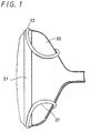
- FIG. 1 of the accompanying drawings shows a conventional cathode-ray tube with an internal magnetic shield similar to that described in EP-A-269498 on which the precharacterizing portion of claim 1 is based.
- a pair of degaussing coils 22 is located over an implosion-resistant band 21 mounted on the side walls of a tube body 20.
- Each of the degaussing coils 22 has an outside diameter ranging from 12 to 20 mm.
- the cathode-ray tube is required to be housed in a relatively large cabinet.
- the cabinet is of a poor appearance as its outer frame or bezel is relatively thick.
- the degaussing coil 22 for the cathode ray tube with the internal magnetic shield is attached to the cabinet. However, it is more difficult to attach the degaussing coil 22 to the cabinet than to attach the degaussing coil 22 to the tube body 20.
- a CRT with an external magnetic shield attached to the anti-implosion ring is disclosed in GB-A-2 202 116.
- the shield carries the degaussing coils aligned along the anti-implosion band which degauss the external shield.
- a cathode-ray tube comprising:
- the height of the degaussing coil on the implosion-resistant band may be relative small.
- the flat portion is effective to prevent the degaussing coil from being undesirably displaced on the implosion-resistant band.
- the flat portion also allows the degaussing coil to be fixed directly to the implosion-resistant band by an attachment.
- FIG. 2 shows a cathode-ray tube according to the present invention.
- the cathode-ray tube has a tube body 1 housing an internal magnetic shield mounted, for example, on the frame of color selecting electrodes in the tube body 1.
- the cathode-ray tube also includes an implosion-resistant band 2 disposed around the side walls of the tube body 1, and a pair of degaussing coils 3 positioned respectively on the upper and lower side walls of the tube body 1 in confronting relationship to each other.
- Each of the degaussing coils 3 is of an annular shape and comprises a flat portion 4 of substantially rectangular cross section and an extension 6 of substantially circular cross section which is joined to opposite ends of the flat portion 4.
- the flat portions 4 of the respective degaussing coils 3 are placed respectively on upper and lower portions of the implosion-resistant band 2, and secured thereto by respective attachments 5.
- the extensions 6 of the respective degaussing coils 3 extend toward a neck 1a of the tube body 1, and are connected to an AC power supply (not shown).
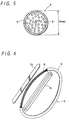
- FIG. 3 shows one of the flat portions 4 of the degaussing coils 3 in cross section.
- the flat portion 4 comprises a case 7 of rectangular cross section and a plurality of copper wires 8 each coated with an insulative layer which are accommodated in the case 7.
- the cathode-ray tube is a 29-inch tube, for example, then the rectangular cross-sectional shape of the case 7 has a width of about 30 mm and a thickness of about 7 mm.
- the degaussing coil comprises 88 turns of a copper wire, for example, and hence the copper wires 8 in the case 7 are part of those 88 turns of a copper wire.
- the case 7 is made of pliable synthetic resin, and comprises a trough-shaped container 7a and a flat cover 7b which is to be placed over the container 7a with the copper wires 8 accommodated therein.
- the flat portion 4 extends along each of the upper and lower walls of the tube body 1, and has a length slightly larger than the horizontal width of the tube body 1 as viewed in front elevation.
- the flat portion 4 has tapered opposite ends.
- the extension 6 of circular cross section has an outside diameter of about 12 mm.
- the extension 6 comprises part of the 88 turns of a copper wire which are wrapped by several layers of an insulative tape 9.
- Each of the degaussing coils 3 may be manufactured as follows:
- a copper wire 8 is wound into 88 turns, for example, and those turns of the copper wire 8 are wrapped by an insulative tape 9 except for a copper wire region corresponding to the flat portion 4.
- the exposed copper wires 8 which are not wrapped by the insulative tape 9 are then fitted into the trough-shaped container 7a of the case 7, and finally the cover 7b is bonded to the container 7a by an adhesive, closing the container 7a.
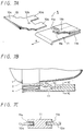
- Each of the degaussing coils 3 is attached to the tube body 1 by an attachment 5 described below.
- the attachment 5 comprises a joint arm 10 and a holder 11, both made of resilient synthetic resin.
- the joint arm 10 is in the form of a stepped rectangular thin member having a pair of spaced rectangular tongues 10a projecting from one end thereof.
- the joint arm 10 has a recess 10b defined in an upper surface thereof near the cavity defined between the tongues 10a.
- the holder 11 comprises a rectangular thin member having a thicker end with a pair of grooves 11a defined respectively in opposite sides thereof.
- the grooves 11a are shaped to receive the respective tongues 10a snugly therein.
- the holder 11 also has a tongue 11b positioned between the grooves 11a and projecting toward the opposite end of the holder 11.
- the tongue 11b has a protrusion 11c projecting from a surface thereof toward but terminating short of the confronting surface of the holder 11.
- the protrusion 11c is shaped to fit snugly in the recess 11b of the joint arm 10.
- an end 10c of the joint arm 10 remote from the tongues 10a is fixed to the implosion-resistant band 2 by adhesive bonding, welding, a screw, or the like, and then the flat portion 4 of the degaussing coil 3 is placed on the end 10c. Thereafter, the joint arm 10 and the holder 11 are put together.
- the tongues 10a of the joint arm 10 are fitted snugly into the respective grooves 11b of the holder 11.
- the holder 11 is moved in the direction indicated by the arrow A in FIG. 7A until the protrusion 11c of the holder 11 is snapped into the recess 10b of the joint arm 10.
- the flat portion 4 of the degaussing coil 3 is now gripped resiliently between and held in position by the joint arm 10 and the holder 11.
- the attachment 5 shown in FIGS. 7A through 7C is actually positioned on the lower wall of the tube body 1.
- the other degaussing coil 3 is attached to the implosion-resistant band 2 by another attachment 5 with its joint arm 10 and holder 11 positioned upside down.
- Each of the degaussing coils 3 may be attached to the implosion-resistant band 2 by a plurality of attachments 5.
- the degaussing coils 3 on the implosion-resistant band 2 may be of a relatively small height. Therefore, the outer frame or bezel of a cabinet which houses the cathode-ray tube may be of a relatively low profile. Consequently, the cathode-ray tube according to the present invention may be accommodated in a relatively small cabinet as is the case with cathode-ray tubes with magnetic shields disposed outside of the tube bodies.
- the flat portion 4 allows the degaussing coil 3 to be fixed directly to the implosion-resistant band 2, i.e., to be mounted on the tube body 1, simply with the attachment 5 which is of a substantially flat configuration in its entirety.
- the degaussing coils 3 can thus be installed in position more easily than if they were attached to the cabinet.
- the flat portion 4 is also effective to prevent the degaussing coil 3 from being undesirably displaced on the implosion-resistant band 2.
- the degaussing coils 3 may be flat throughout their entire length insofar as their rigidity and shape are adjusted to match the funnel shape of the tube body 1.
- the specified dimensions of the flat portions 4 of the degaussing coils 3, the specified dimensions of the degaussing coils 3, and the specified number of turns of the copper wire 8 of the degaussing coils 3 are given by way of example only, and may be varied to suit cathode-ray tubes of various sizes and dimensions.
Landscapes
- Physics & Mathematics (AREA)
- Electromagnetism (AREA)
- Video Image Reproduction Devices For Color Tv Systems (AREA)
- Vessels, Lead-In Wires, Accessory Apparatuses For Cathode-Ray Tubes (AREA)
- Electrodes For Cathode-Ray Tubes (AREA)
Claims (7)
- Kathodenstrahlröhre mit:einem Röhrenkörper (1) mit einer inneren magnetischen Abschirmung, die in ihm aufgenommen ist, wobei der Röhrenkörper Seitenwände, einen Halsabschnitt (1a) und einen sich verjüngenden Übergangsabschnitt aufweist, der die Seitenwände und den Halsabschnitt (1a) verbindet;einem implosionsfesten Band (2), das an den Seitenwänden des Röhrenkörpers (1) angebracht ist; undeiner ringförmigen Entmagnetisierungsspule (3), die an dem implosionsfesten Band (2) angebracht ist,dadurch gekennzeichnet, daß die Entmagnetisierungsspule (3) einen flachen Abschnitt (4) aufweist, der an dem implosionsfesten Band (2) angebracht ist, und eine Erweiterung (6) mit im wesentlichen kreisförmigem Querschnitt aufweist, die mit den voneinander abgewandten Enden des flachen Abschnitts (4) verbunden sind und sich über den sich verjüngenden Übergangsabschnitt des Röhrenkörpers (1) erstrecken.
- Kathodenstrahlröhre nach Anspruch 1,
bei der der flache Abschnitt (4) im wesentlichen einen rechteckigen Querschnitt aufweist. - Kathodenstrahlröhre nach Anspruch 2,
bei der der flache Abschnitt (4) ein Gehäuse (7) aus einem biegbaren Kunststoff aufweist, das einen im wesentlichen rechteckigen Querschnitt und mehrere Drähte (8) aufweist, die in dem Gehäuse (7) aufgenommen sind, wobei die Drähte (8) Teil der Windungen der Entmagnetisierungsspule (3) sind. - Kathodenstrahlröhre nach einem der Ansprüche 1, 2 oder 3,
weiterhin aufweisend eine Anbringung (5) zur Anbringung des flachen Abschnitts (4) der Entmagnetisierungsspule (3) an dem implosionsfesten Band (2) an den Seitenwänden der Röhre. - Kathodenstrahlröhre nach Anspruch 4,
bei der die Anbringung (5) eine im wesentlichen flache Form aufweist und einen Verbindungsarm (10), der mit dem implosionsfesten Band (2) durch einen im wesentlichen flachen Abschnitt (10c) verbunden ist, sowie einen im wesentlichen flachen Halter (11) aufweist, der mit dem anderen Ende des Verbindungsarms (10) verbunden ist und dem im wesentlichen flachen Endabschnitt (10c) gegenübersteht, wobei der flache Abschnitt (4) der Entmagnetisierungsspule elastisch zwischen dem im wesentlichen flachen Endabschnitt (10c) und dem Halter (11) gegriffen ist. - Kathodenstrahlröhre nach einem der vorhergehenden Ansprüche,
bei der ein Paar Entmagnetisierungsspulen (3) an dem implosionsfesten Band (2) einander gegenüberstehend an voneinander abgewandten Enden der Seitenwände angebracht ist, wobei jede der Entmagnetisierungsspulen (3) einen flachen Abschnitt (4) aufweist. - Kathodenstrahlröhre nach Anspruch 6, wenn rückbezogen auf Anspruch 4 oder 5,
aufweisend ein Paar an Anbringungen (5), wobei die flachen Abschnitte (4) jeweils an dem implosionsfesten Band (2) durch eine der Anbringungen (5) angebracht sind.
Applications Claiming Priority (2)
| Application Number | Priority Date | Filing Date | Title |
|---|---|---|---|
| JP3198026A JPH0541176A (ja) | 1991-08-07 | 1991-08-07 | 陰極線管 |
| JP198026/91 | 1991-08-07 |
Publications (2)
| Publication Number | Publication Date |
|---|---|
| EP0527057A1 EP0527057A1 (de) | 1993-02-10 |
| EP0527057B1 true EP0527057B1 (de) | 1997-02-05 |
Family
ID=16384292
Family Applications (1)
| Application Number | Title | Priority Date | Filing Date |
|---|---|---|---|
| EP92307218A Expired - Lifetime EP0527057B1 (de) | 1991-08-07 | 1992-08-06 | Kathodenstrahlrohr mit Entmagnetisierungsspulen mit flachen Teilen befestigt an einem Implosionsschutzband |
Country Status (5)
| Country | Link |
|---|---|
| US (1) | US5382868A (de) |
| EP (1) | EP0527057B1 (de) |
| JP (1) | JPH0541176A (de) |
| KR (1) | KR930005081A (de) |
| DE (1) | DE69217292T2 (de) |
Cited By (1)
| Publication number | Priority date | Publication date | Assignee | Title |
|---|---|---|---|---|
| US6204894B1 (en) | 1998-07-17 | 2001-03-20 | Thomson Licensing S.A. | Clip attached to a band of a cathode-ray tube |
Families Citing this family (3)
| Publication number | Priority date | Publication date | Assignee | Title |
|---|---|---|---|---|
| DE69707225T2 (de) * | 1996-04-09 | 2002-06-13 | Koninklijke Philips Electronics N.V., Eindhoven | Bildanzeigevorrichtung mit gegen das erdmagnetfeld abgeschirmter farbbildröhre |
| KR0139540Y1 (ko) * | 1996-05-02 | 1999-03-20 | 김광호 | 화상표시장치의 전자관 접지장치 |
| KR100863950B1 (ko) * | 2002-05-14 | 2008-10-16 | 삼성에스디아이 주식회사 | 음극선관 |
Family Cites Families (9)
| Publication number | Priority date | Publication date | Assignee | Title |
|---|---|---|---|---|
| US3879633A (en) * | 1963-12-19 | 1975-04-22 | Rca Corp | Television degaussing system with saddle-type coils adjacent CRT cone |
| DE6945729U (de) * | 1969-11-26 | 1970-04-30 | Licentia Gmbh | Fabrfernsehbildrohre mit entmagnetisierungsvorrichtung |
| CA977406A (en) * | 1972-04-14 | 1975-11-04 | Yoshiichi Matsushima | Degaussing device for colour cathode ray tubes |
| US4236184A (en) * | 1978-09-25 | 1980-11-25 | Zenith Radio Corporation | Multi-function structure for a color cathode ray tube |
| JPS55111048A (en) * | 1979-02-20 | 1980-08-27 | Toshiba Corp | Implosion-proof cathode ray tube and manufacturing method |
| FR2606574B1 (fr) * | 1986-11-07 | 1989-01-13 | Videocolor | Dispositif de protection de tubes cathodiques a masque vis-a-vis du champ magnetique terrestre |
| JPS63221790A (ja) * | 1987-03-11 | 1988-09-14 | Sony Corp | 陰極線管 |
| US5200673A (en) * | 1988-10-31 | 1993-04-06 | Victor Company Of Japan, Ltd. | Method and device for suppression of leakage of magnetic flux in display apparatus |
| US5038078A (en) * | 1989-06-05 | 1991-08-06 | Rca Licensing Corporation | Degaussing coil attachment arrangement |
-
1991
- 1991-08-07 JP JP3198026A patent/JPH0541176A/ja active Pending
-
1992
- 1992-08-01 KR KR1019920013891A patent/KR930005081A/ko not_active Withdrawn
- 1992-08-06 EP EP92307218A patent/EP0527057B1/de not_active Expired - Lifetime
- 1992-08-06 DE DE69217292T patent/DE69217292T2/de not_active Expired - Fee Related
- 1992-08-07 US US07/925,752 patent/US5382868A/en not_active Expired - Fee Related
Cited By (1)
| Publication number | Priority date | Publication date | Assignee | Title |
|---|---|---|---|---|
| US6204894B1 (en) | 1998-07-17 | 2001-03-20 | Thomson Licensing S.A. | Clip attached to a band of a cathode-ray tube |
Also Published As
| Publication number | Publication date |
|---|---|
| JPH0541176A (ja) | 1993-02-19 |
| KR930005081A (ko) | 1993-03-23 |
| DE69217292D1 (de) | 1997-03-20 |
| US5382868A (en) | 1995-01-17 |
| EP0527057A1 (de) | 1993-02-10 |
| DE69217292T2 (de) | 1997-06-05 |
Similar Documents
| Publication | Publication Date | Title |
|---|---|---|
| EP0527057B1 (de) | Kathodenstrahlrohr mit Entmagnetisierungsspulen mit flachen Teilen befestigt an einem Implosionsschutzband | |
| US4858016A (en) | Cathode ray tube having an improved implosion proof structure | |
| US4359707A (en) | Picture tube demagnetizing coil arrangement | |
| US4700260A (en) | Degaussing coil and ground strap mounting arrangement | |
| US5304891A (en) | Cathode-ray tube display device | |
| US5038078A (en) | Degaussing coil attachment arrangement | |
| JP3136673B2 (ja) | 偏向ヨーク | |
| US5355107A (en) | Deflection yoke with leaking magnetic field prevention coils | |
| JPH0295987U (de) | ||
| JPS5937951Y2 (ja) | 近接スイツチ | |
| KR200142309Y1 (ko) | 편향 요크 | |
| JPH0455403Y2 (de) | ||
| JPH08194015A (ja) | 電流検出器 | |
| JPH0541485Y2 (de) | ||
| JPH0454675Y2 (de) | ||
| JP2689423B2 (ja) | 消磁コイル・アース線取付装置 | |
| JPH0735287Y2 (ja) | 偏向ヨーク | |
| JPS5850609Y2 (ja) | 偏向ヨ−ク | |
| JPH06310053A (ja) | 陰極線管用偏向ヨーク | |
| JPH0537451Y2 (de) | ||
| JPS5812361Y2 (ja) | 電磁偏向ヨ−ク | |
| JPH0240905A (ja) | フライバックトランス | |
| JP3636297B2 (ja) | 偏向ヨーク | |
| JPS61110944A (ja) | 偏向ヨ−ク | |
| JP2682333B2 (ja) | 偏向ヨーク装置 |
Legal Events
| Date | Code | Title | Description |
|---|---|---|---|
| PUAI | Public reference made under article 153(3) epc to a published international application that has entered the european phase |
Free format text: ORIGINAL CODE: 0009012 |
|
| AK | Designated contracting states |
Kind code of ref document: A1 Designated state(s): DE FR GB |
|
| 17P | Request for examination filed |
Effective date: 19930719 |
|
| 17Q | First examination report despatched |
Effective date: 19941227 |
|
| GRAG | Despatch of communication of intention to grant |
Free format text: ORIGINAL CODE: EPIDOS AGRA |
|
| GRAH | Despatch of communication of intention to grant a patent |
Free format text: ORIGINAL CODE: EPIDOS IGRA |
|
| GRAH | Despatch of communication of intention to grant a patent |
Free format text: ORIGINAL CODE: EPIDOS IGRA |
|
| GRAA | (expected) grant |
Free format text: ORIGINAL CODE: 0009210 |
|
| AK | Designated contracting states |
Kind code of ref document: B1 Designated state(s): DE FR GB |
|
| REF | Corresponds to: |
Ref document number: 69217292 Country of ref document: DE Date of ref document: 19970320 |
|
| ET | Fr: translation filed | ||
| PLBE | No opposition filed within time limit |
Free format text: ORIGINAL CODE: 0009261 |
|
| STAA | Information on the status of an ep patent application or granted ep patent |
Free format text: STATUS: NO OPPOSITION FILED WITHIN TIME LIMIT |
|
| 26N | No opposition filed | ||
| PGFP | Annual fee paid to national office [announced via postgrant information from national office to epo] |
Ref country code: DE Payment date: 20010730 Year of fee payment: 10 |
|
| PGFP | Annual fee paid to national office [announced via postgrant information from national office to epo] |
Ref country code: FR Payment date: 20010810 Year of fee payment: 10 |
|
| REG | Reference to a national code |
Ref country code: GB Ref legal event code: IF02 |
|
| PG25 | Lapsed in a contracting state [announced via postgrant information from national office to epo] |
Ref country code: DE Free format text: LAPSE BECAUSE OF NON-PAYMENT OF DUE FEES Effective date: 20030301 |
|
| PG25 | Lapsed in a contracting state [announced via postgrant information from national office to epo] |
Ref country code: FR Free format text: LAPSE BECAUSE OF NON-PAYMENT OF DUE FEES Effective date: 20030430 |
|
| REG | Reference to a national code |
Ref country code: FR Ref legal event code: ST |
|
| PGFP | Annual fee paid to national office [announced via postgrant information from national office to epo] |
Ref country code: GB Payment date: 20050803 Year of fee payment: 14 |
|
| GBPC | Gb: european patent ceased through non-payment of renewal fee |
Effective date: 20060806 |
|
| PG25 | Lapsed in a contracting state [announced via postgrant information from national office to epo] |
Ref country code: GB Free format text: LAPSE BECAUSE OF NON-PAYMENT OF DUE FEES Effective date: 20060806 |