EP0527652A2 - Système de détection optique pour des colonnes capillaires - Google Patents
Système de détection optique pour des colonnes capillaires Download PDFInfo
- Publication number
- EP0527652A2 EP0527652A2 EP19920307419 EP92307419A EP0527652A2 EP 0527652 A2 EP0527652 A2 EP 0527652A2 EP 19920307419 EP19920307419 EP 19920307419 EP 92307419 A EP92307419 A EP 92307419A EP 0527652 A2 EP0527652 A2 EP 0527652A2
- Authority
- EP
- European Patent Office
- Prior art keywords
- light
- column
- lens
- collecting
- capillary
- Prior art date
- Legal status (The legal status is an assumption and is not a legal conclusion. Google has not performed a legal analysis and makes no representation as to the accuracy of the status listed.)
- Ceased
Links
Images
Classifications
-
- G—PHYSICS
- G01—MEASURING; TESTING
- G01N—INVESTIGATING OR ANALYSING MATERIALS BY DETERMINING THEIR CHEMICAL OR PHYSICAL PROPERTIES
- G01N30/00—Investigating or analysing materials by separation into components using adsorption, absorption or similar phenomena or using ion-exchange, e.g. chromatography or field flow fractionation
- G01N30/02—Column chromatography
- G01N30/62—Detectors specially adapted therefor
- G01N30/74—Optical detectors
Definitions
- This invention relates to apparatus for measuring the optical properties of a sample contained in a capillary column, and is particularly useful in connection with measuring light absorbance of a fluid flowing through a capillary separation column.
- GC gas chromatography
- HPLC high performance liquid chromatography
- SFC supercritical fluid chromatography
- CE capillary electrophoresis
- a peak may consist of a very small mass of material which may elute over a relatively short time duration.
- optical detection methods are in widespread use in HPLC, SFC and CE. Perhaps the most commonly used optical detection technique is absorbance detection wherein the optical absorbance of the sample flowing from the separation column is continuously measured. fluorescence detection is another very commonly used technique. By measuring changes in the optical absorbance or fluorescence from background levels, qualitative and quantitative information about the sample may be obtained.
- optical detection techniques used in connection with separation columns may be divided into two categories: those in which detection is performed "on-column" and those in which detection is performed using a flow-cell.
- On-column measurements are made by observing the properties of the sample near the end of the separation column but while the peak is still in the column.
- flow-cells involve use of specially designed volumes for containing the flowing sample after it has eluted from the separation column.
- An example of a flow cell design for use in a liquid chromatography is shown in U.S. Pat. No. 4,006,990.
- Flow-cells can be designed to provide advantageous optical properties to enhance detection, but inherently add dead volume and cause fluid turbulence resulting in undesired peak broadening.
- on-column detection while not suffering from the peak broadening problems associated with flow cells, does not offer very good optical properties.
- on-column detection has been the preferred method for use with capillary separation columns.
- a basic design for on-column detection in capillary column HPLC is shown in U.S. Pat. No. 4,375,163. This patent also contains a more thorough discussion of the limitations of flow cells when dealing with very small sample volumes.
- On-column detection techniques have the disadvantage, described above, of not offering good optical properties.
- a major problem with on-column optical detection in connection with capillary columns is due to light which is scattered and thereafter interferes with detection.
- a beam of light incident on a column will interact not only with the fluid within the column but also with the surrounding glass wall.
- a typical capillary column may have, for example, an outer diameter of 375 ⁇ m and an inner diameter of only 75 ⁇ m.
- a cross section of such a column has a 75 ⁇ m bore surrounded by two walls twice (150 ⁇ m) as wide. If light is evenly incident on the entire column, the majority will interact with the column walls rather than the sample. Scattered light will not only cause non-linearity in detector response at high absorption, it will also cause a reduction from the true absorption at low absorption.
- Another object of the present invention is to provide a method and apparatus which minimizes light scatter in an on-column optical detection system.
- Yet another object of the present invention is to provide a method and apparatus which minimizes the adverse effects of scattered light in an on-column optical detection system employing a capillary column.
- Still a further object of the present invention is to provide a unique lens design which achieves the foregoing objects.
- a light source for illiminatingg sample flowing through a capillary separation column means for focussing the light onto the capillary column, means for masking said focussed light and thereby at least partially preventing it from striking the walls of the column, means for collecting light emanating from said column, spatial filter means for masking said light collecting means, thereby further reducing the effects of scattered light, and photodetector means for measuring light transmitted by said light collecting means.
- said light focussing means and said light collecting means comprise a set of matched lenses equidistant from the capillary column, each lens being removed from said column a distance approximately equal to the focal length of the lens.
- these lenses are formed as part of an integral "monolens" having at least two hemispherical portions and a central bore wherein the capillary column is positioned.
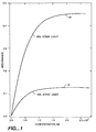
- FIG. 1 is plot of two curves showing the effect of scattered light on absorbance for two different levels of stray light.
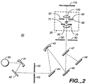
- FIG. 2 is a schematic diagram of an overall detection system according to the present invention in an absorbance detector.
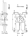
- FIG. 3 is a schematic diagram of an embodiment of the present invention also shown being used in an absorbance detection mode.
- FIG. 4 is a plan view of an embodiment of the present invention using a novel monolens design.
- A abc
- A the amount of light absorbed by a sample
- a the molar absorptivity of the sample
- b the path length of the light as it travels through the sample
- c the concentration.
- I0 the light incident on the sample region
- I s the stray light intensity
- I the light transmitted from the sample region
- I′ I + I s is the total transmitted light intensity.
- FIG. 1 is a plot of Eq. 4, based on theoretical calculations, assuming the presence of 35% (curve 10) and 75% (curve 15) stray light. The pronounced effects of stray light can be clearly seen as the curves approach limiting absorbencies of .45 and .12 respectively. Data collected in connection with the development of the present invention shows that the amount of stray or scattered light present in a capillary on-column optical detection system of the prior art can easily be in the range of 35 - 75%.
- the present invention is directed to apparatus and methods for minimizing the effects of stray light so as to provide greater dynamic range and improved linearity of detector response.
- the reduction of stray light is accomplished using a combination of techniques each of which reduces stray light in the system.
- FIG. 2 An overall absorbance detector 20 in accordance with a preferred embodiment of the present invention is shown schematically in FIG. 2 to which we now turn.
- a lamp 30 provides light for use in the detector. This light is processed in a known manner by optical elements 41 - 47. In the embodiment shown, one of these optical elements, grating 46, is used to provide monochromatic light.
- grating 46 one of these optical elements, grating 46, is used to provide monochromatic light.
- the term "light” is intended to include radiation in the ultraviolet (UV) portion of the electromagnetic spectrum, in addition to "visible” and infrared light. UV light is very commonly used in absorbance and fluorescence detection in HPLC, CE and SFC.
- Light from grating 46 passes through exit slit 50 and follows a path through focussing lens 60, slit 70, capillary column 80, spatial filter 90, and collecting lens 100 according to the present invention and as described below in greater detail in connection with FIG. 3.
- a portion of the unfiltered, unabsorbed light which exits collecting lens 100 reaches photodiode 110 where it is detected using known current measurement techniques.
- an embodiment of system 20 used by the inventors is a modified version of a commercially available UV detector design which can be purchased as Varian Model No. 2550. This commercial detector is designed for use with large-bore HPLC and requires modification for use with capillary columns.
- FIG. 3 ray tracings are shown in connection with the apparatus of the present invention to illustrate the methods employed to minimize the stray light reaching photodiode 110.
- Monochromatic light passing through exit slit 50 is shown having a slight amount of divergence. In the embodiment using the aforementioned commercial system, the angle of divergence was approximately 8°.
- This light is captured by lens 60 and focussed onto capillary column 80.
- Capillary column 80 is made of fused silica which is optically transparent to light radiation at the wavelengths of interest and, in particular, to UV light. Any coating on the column is removed in the area where light is to be focussed, as described in the aforementioned U.S. Pat. No. 4,375,163.
- slit 70 is positioned in front of column 80 to block or mask light which would otherwise strike the column walls and be scattered.
- the width of the slit should be approximately the same sizes as the inner diameter of the column to minimize the amount of light striking a portion of the column wall that is not in front of the column bore.
- the miniature size of the slit will make the task of attaining and maintaining the nearly perfect optical alignment which is required very difficult. These alignment problems are mitigated by the use of a 100 ⁇ m slit. If a slit smaller than the diameter of the column, i.e. , less than 75 ⁇ m were used, or if alignment is not accurate, the illumination of the sample would be reduced, to the detriment of the signal-to-noise ratio of the system.
- lenses 60 and 100 are a matched pair and are coaxially aligned. In one embodiment, two commercially available 6 mm diameter quartz lenses with a 5 mm focal length were used. Moreover, as is explained in greater detail below, it has been found that by placing lens 100 approximately the same distance from the column as lens 60, the effects of stray light are further reduced. It should be noted that, in this configuration, the distance between the column and either lens is approximately the focal length of the lens. Thus, light exiting collecting lens 100 will have approximately the same angle of divergence as the light reaching the lens 60 in accordance with well known principles of optics.
- a mask or spatial filter 90 is placed in front of lens 100, i.e. , between column 80 and the lens.
- spatial filter 90 had an aperture diameter of 2 mm and thus blocks a significant portion of the periphery of the lens. Use of a spatial filter in front of lens 100 was found to further reduce the amount of stray light reaching photodiode 110.
- Optical design C is similar to that shown in FIG. 3, however, the collecting lens is positioned farther away from the column, i.e. , 9 mm, with the result that the collected light is focused onto the photodiode.
- design E it should be noted that placing the collecting lens at a distance approximately equal to its focal length, so that the light from the column is slightly divergent, improves sensitivity by a factor of almost three.
- use of a mask improves sensitivity by a factor greater than five over a comparable maskless design, i.e ., design D.
- the primary source of stray light emanating from the column is, as noted above, from the column walls.
- Use of a ray tracing programs has shown that this light will mostly be at the periphery of the beam passing through the sample in the column, and will stay at the periphery. Placement of a properly sized spatial filter or mask will prevent this peripheral light from reaching the photodiode. It is believed that even more dramatic improvements in the detection limit can be obtained by carefully sizing and configuring the spatial filter.
- the mask need not have a circular aperture since the sample is not circular. Rather the sample is closer to being cylindrical. Thus, a rectangular or elliptical aperture is likely to be an improvement over the design tested.
- the spatial filter is placed in front of the collecting lens
- the spatial filter is placed in front of the photodiode. Again, the purpose of this is to block the periphery of the light beam where most of the scattered light is present.
- the photodiode is, effectively, self-masking due to the placement of collecting lens 100.
- collecting lens 100 is positioned a distance approximately equal to its focal length from the column. As explained above, as a result of this placement, light passing through the lens is substantially collimated or even slightly divergent. Assuming that the photodiode is properly sized, light at the periphery of the beam from lens 100 will miss the photodiode. Again, the primary component of the peripheral light is light scattered from the column walls. In comparison, in design C, where the collecting lens is positioned so as to produce a converging beam, the peripheral scattered light is focussed on the photodiode.
- concentration detection limits of uracil obtained in accordance with the present invention correspond to a mass detection limit of 0.01 pg. This is a factor of five improvement over the detection limit reported for a commercially available UV absorbance detector. Similar tests using anthracene as a sample, resulted in a concentration detection limit of 5.4 x 10 ⁇ 8 M, which translates to a mass detection limit of 38 fg. This is a factor of five improvement over the maskless two lens design (i.e. , design E), and is an order of magnitude better than a commercially available spherical ball detector.
- Anthracene was used because of its large molar absorptivity and, as a result, has become a standard in the chromatography field for comparing UV detectors.
- the detection limit obtained for anthracene is close to the theoretically calculated value of the system detection limit based on the fact that such a system is photon shot noise limited.
- a "monolens" was constructed in accordance with the design of FIG. 4.
- the monolens comprises a central quartz body portion 200 with four quartz hemispherical lobes 210, 220, 230 and 240, respectively, which serve as lenses.
- Hemispherical lobes 210 and 230 are coaxially aligned, as are hemispherical lobes 220 and 240, with all four having their axes lying on the same plane.
- the quartz hemispherical attachments are glued to body portion 200 using glue which is transparent to the light frequencies of interest.
- the body and hemispherical lobes can be machined out of a single piece of quartz so as to form an integral unit. Although four hemispherical lobes are shown, in most applications it will only be necessary to provide two such lobes.
- the monolens of FIG. 4 was designed in order to allow both absorbance detection and fluorescence detection. For fluorescence detection it is desirable to position the collecting lens at right angles to the focussing lens to further minimize the effects of stray light.
- a bore 250 barely wide enough to accommodate capillary column 80.
- the central bore was specified to be 0.5 mm in diameter. This allows the monolens to be used for on-column detection. Accordingly, the column is inserted into the bore where it is surrounded by the monolens. While the bore should be close in diameter to the outer diameter of the capillary column, it is inevitable that there will be gaps between the column and the monolens. To minimize refraction problems which could arise as the light travels through these gaps, the space between the monolens and the column may be filled with a fluid having an index of refraction nearly the same as quartz.
- the body portion and hemispherical lobes of the monolens are dimensioned such that light incident on one of the hemispherical lobes is focussed at a point at the center of column 80, i.e. , the center of bore 250.
- the focal spot can be substantially smaller than the 1 mm focal spot described above in respect to a commercially available lens. If the focal spot is made small enough, for example, 75 - 100 ⁇ m, and if the design is accurately made, there is no longer a need for a slit to partially block light from striking the column walls. Light will not strike the periphery of the column walls by virtue of being tightly focussed.
- the focal spot was calculated to be 83 ⁇ m, or just slightly larger than the inner diameter of the capillary column.
- a spatial filter 260 is placed in front of focussing lens 210 and another spatial filter 270 is places behind collecting lens 230.
- spatial filters 260 and 270 also serve to keep the monolens properly positioned by holding it at shoulders 280 adjacent the hemispherical lobes. Spatial filters 260 and 270 are, in turn, held in position by lens holders 290 and 295 respectively.
- spatial filters 260 and 270 nonetheless serve to reduce the amount of light scatter in the optical detector.
- light from exit slit 50 will be slightly divergent. The amount of divergence is 8° for the aforementioned Varian 2550 detector.
- Spatial filter 260 blocks some of the diverging light, and further blocks other stray light which may be present in the system.
- light transmitted by collecting lens 230 will be slightly divergent, with the scattered light being mostly at the periphery of the transmitted beam.
- Spatial filter 270 helps block the diverging peripheral portion of the beam.
- the light collecting means of the invention preferably produces a beam which does not converge. It may comprise a lens, as may the light focussing means.
- the light focussing means and the light collecting means may comprise a set of coaxially aligned matched lenses based equidistant from the column. These lenses may be spaced a distance from the column equal to the focal length of said lenses.
- the photodetector may comprise a photodiode having a planar surface and the photodiode may be configured and positioned such that light in the peripheral portion of the beam emanating from the collecting lens does not strike the photodiode surface.
- Second spatial filter means may be provided adjacent said photodiode planar surface.
- the width of said slit means may be no greater than 1.5 times the inner diameter of the column.
- the light source may produce monochromatic light.
- the monolens which has first and second hemispherical portions they may be separately formed and thereafter attached to the body portion or in an alternative arrangement the hemispherical portions and the body portion may be formed from a unitary block.
Landscapes
- Physics & Mathematics (AREA)
- Spectroscopy & Molecular Physics (AREA)
- Health & Medical Sciences (AREA)
- Life Sciences & Earth Sciences (AREA)
- Chemical & Material Sciences (AREA)
- Analytical Chemistry (AREA)
- Biochemistry (AREA)
- General Health & Medical Sciences (AREA)
- General Physics & Mathematics (AREA)
- Immunology (AREA)
- Pathology (AREA)
- Investigating Or Analysing Materials By Optical Means (AREA)
- Optical Measuring Cells (AREA)
- Investigating, Analyzing Materials By Fluorescence Or Luminescence (AREA)
- Investigating Materials By The Use Of Optical Means Adapted For Particular Applications (AREA)
Priority Applications (1)
| Application Number | Priority Date | Filing Date | Title |
|---|---|---|---|
| EP95201349A EP0672904A1 (fr) | 1991-08-13 | 1992-08-13 | Lentille unique pour utilisage dans un système de détection optique |
Applications Claiming Priority (2)
| Application Number | Priority Date | Filing Date | Title |
|---|---|---|---|
| US07/744,563 US5235409A (en) | 1991-08-13 | 1991-08-13 | Optical detection system for capillary separation columns |
| US744563 | 1991-08-13 |
Related Child Applications (2)
| Application Number | Title | Priority Date | Filing Date |
|---|---|---|---|
| EP95201349A Division EP0672904A1 (fr) | 1991-08-13 | 1992-08-13 | Lentille unique pour utilisage dans un système de détection optique |
| EP95201349.8 Division-Into | 1992-08-13 |
Publications (2)
| Publication Number | Publication Date |
|---|---|
| EP0527652A2 true EP0527652A2 (fr) | 1993-02-17 |
| EP0527652A3 EP0527652A3 (fr) | 1993-04-21 |
Family
ID=24993167
Family Applications (2)
| Application Number | Title | Priority Date | Filing Date |
|---|---|---|---|
| EP19920307419 Ceased EP0527652A3 (fr) | 1991-08-13 | 1992-08-13 | Système de détection optique pour des colonnes capillaires |
| EP95201349A Withdrawn EP0672904A1 (fr) | 1991-08-13 | 1992-08-13 | Lentille unique pour utilisage dans un système de détection optique |
Family Applications After (1)
| Application Number | Title | Priority Date | Filing Date |
|---|---|---|---|
| EP95201349A Withdrawn EP0672904A1 (fr) | 1991-08-13 | 1992-08-13 | Lentille unique pour utilisage dans un système de détection optique |
Country Status (2)
| Country | Link |
|---|---|
| US (1) | US5235409A (fr) |
| EP (2) | EP0527652A3 (fr) |
Cited By (6)
| Publication number | Priority date | Publication date | Assignee | Title |
|---|---|---|---|---|
| EP0672904A1 (fr) | 1991-08-13 | 1995-09-20 | Varian Associates, Inc. | Lentille unique pour utilisage dans un système de détection optique |
| WO2001061313A3 (fr) * | 2000-02-19 | 2002-02-28 | Mwi Inc Dba Danam Electronics | Dispositif optique et procede de diffusion multi-angulaire de lumiere laser |
| EP3444603A3 (fr) * | 2017-08-15 | 2019-03-06 | Advanced Analytical Technologies, Inc. | Système d'électrophorèse capillaire multicanaux à absorbance uv |
| US11016057B2 (en) | 2012-03-15 | 2021-05-25 | Agilent Technologies, Inc. | Pulse-field multiplex capillary electrophoresis system |
| US11067536B2 (en) | 2011-04-13 | 2021-07-20 | Agilent Technologies, Inc. | Capillary electrophoresis system |
| US11340191B2 (en) | 2012-03-15 | 2022-05-24 | Agilent Technologies, Inc. | UV-absorbance multichannel capillary electrophoresis system |
Families Citing this family (18)
| Publication number | Priority date | Publication date | Assignee | Title |
|---|---|---|---|---|
| US5395502A (en) * | 1988-11-14 | 1995-03-07 | Anthony R. Torres | Apparatus for performing and universally detecting capillary isoelectric focusing without mobilization using concentration gradient imaging systems |
| US5784154A (en) * | 1992-01-13 | 1998-07-21 | Anthony R. Torres | Electrophoresis separation in a capillary passage |
| US5269901A (en) * | 1992-11-13 | 1993-12-14 | Bio-Rad Laboratories, Inc. | HPCE capillary cartridge for uncoiled capillaries with liquid coolant |
| US5757482A (en) * | 1995-04-20 | 1998-05-26 | Perseptive Biosystems, Inc. | Module for optical detection in microscale fluidic analyses |
| US5582705A (en) * | 1995-05-19 | 1996-12-10 | Iowa State University Research Foundation, Inc. | Multiplexed capillary electrophoresis system |
| US5760399A (en) * | 1995-10-02 | 1998-06-02 | Foss Nirsystems, Inc. | Measurement of transmission spectra of pharmaceutical tablets |
| US6063251A (en) * | 1997-05-30 | 2000-05-16 | Spectrumedix Corporation | Electrically insulated capillary arrays for electrophoretic applications |
| WO1999000664A1 (fr) * | 1997-06-30 | 1999-01-07 | Spectrumedix Corporation | Systeme electrophoretique capillaire parallel automatique |
| US6365024B1 (en) | 1997-06-30 | 2002-04-02 | Spectrumedix Corporation | Motorized positioning apparatus having coaxial carrousels |
| US6027627A (en) * | 1997-06-30 | 2000-02-22 | Spectrumedix Corporation | Automated parallel capillary electrophoretic system |
| US6126804A (en) * | 1997-09-23 | 2000-10-03 | The Regents Of The University Of California | Integrated polymerase chain reaction/electrophoresis instrument |
| US6239871B1 (en) | 1999-08-24 | 2001-05-29 | Waters Investments Limited | Laser induced fluorescence capillary interface |
| US6352633B1 (en) * | 1999-08-31 | 2002-03-05 | Spectrumedix Corporation | Automated parallel capillary electrophoresis system with hydrodynamic sample injection |
| US6667808B2 (en) | 2000-03-08 | 2003-12-23 | Thermo Electron Scientific Instruments Corporation | Multifunctional fourier transform infrared spectrometer system |
| US7250098B2 (en) * | 2001-09-28 | 2007-07-31 | Applera Corporation | Multi-capillary array electrophoresis device |
| JP6804436B2 (ja) * | 2014-05-15 | 2020-12-23 | ブリガム・ヤング・ユニバーシティBrigham Young University | キャピラリー液体クロマトグラフィーのための低検出限界で低電力小型ledベースの紫外線吸光検出器 |
| WO2017165403A1 (fr) * | 2016-03-21 | 2017-09-28 | Nueon Inc. | Procédés et appareil de spectrométrie à maillage poreux |
| EP3812741B1 (fr) * | 2018-06-22 | 2024-09-11 | Hitachi High-Tech Corporation | Appareil d'électrophorèse |
Family Cites Families (22)
| Publication number | Priority date | Publication date | Assignee | Title |
|---|---|---|---|---|
| GB1155438A (en) * | 1966-09-14 | 1969-06-18 | Ceskoslovenska Akademie Ved | Photometer with Limited Light-Beam in Flow-Through Measuring Cell |
| US3512889A (en) * | 1967-03-02 | 1970-05-19 | Smithkline Corp | Spectrophotometer with plural dispersion using a single monochromator |
| US3573470A (en) * | 1968-03-28 | 1971-04-06 | California Inst Of Techn | Plural output optimetric sample cell and analysis system |
| US3869614A (en) * | 1973-03-16 | 1975-03-04 | Varian Associates | Phosphor assembly for ultraviolet light absorption detector |
| JPS5081578A (fr) * | 1973-11-21 | 1975-07-02 | ||
| US4006990A (en) * | 1974-07-22 | 1977-02-08 | Varian Associates | Convergent light illuminated flow cell for liquid chromatography |
| US4192614A (en) * | 1975-02-06 | 1980-03-11 | The Perkin-Elmer Corporation | L/C detector cell assembly |
| US3999856A (en) * | 1976-01-02 | 1976-12-28 | Monsanto Research Corporation | Diffractometric refractometer |
| US4199260A (en) * | 1978-08-21 | 1980-04-22 | Technicon Instruments Corporation | Apparatus and method for determining the concentration in a sample |
| US4375163A (en) * | 1981-01-08 | 1983-03-01 | Varian Associates, Inc. | Method and apparatus for on-column detection in liquid chromatography |
| JPS5892844A (ja) * | 1981-11-28 | 1983-06-02 | Olympus Optical Co Ltd | 比色測定方法および装置 |
| US4475813A (en) * | 1982-08-30 | 1984-10-09 | Milton Roy Company | Divergent light optical systems for liquid chromatography |
| US4747687A (en) * | 1984-06-08 | 1988-05-31 | Milton Roy Company | Ball cell windows for spectrophotometers |
| EP0168939A3 (fr) * | 1984-06-13 | 1987-08-05 | Varian Associates, Inc. | Détecteur d'absorption pour un effluent de chromatographie en phase liquide |
| DE3424108A1 (de) * | 1984-06-29 | 1986-01-09 | Bernhard Prof. Dr.-Ing. 4300 Essen Schrader | Probenanordnung zur spektrometrie, verfahren zur messung von lumineszenz und streuung und verwendung der probenanordnung |
| US4826660A (en) * | 1987-05-07 | 1989-05-02 | Becton, Dickinson And Company | Detector assembly for analyzer instrument |
| US4795262A (en) * | 1987-07-29 | 1989-01-03 | The Regents Of The Univerity Of Michigan | Liquid chromatography absorbance detector |
| JP2635992B2 (ja) * | 1988-03-24 | 1997-07-30 | 興和株式会社 | 微粒子測定装置 |
| US5037199A (en) * | 1989-02-22 | 1991-08-06 | Linear Instruments Corporation | Ball lens micro-cell |
| ATE112181T1 (de) * | 1989-06-20 | 1994-10-15 | Claudio Bonini | Prüfröhrchen mit einer linsenförmigen aussenfläche, insbesondere für automatische klinische analysen. |
| US5074658A (en) * | 1989-07-31 | 1991-12-24 | Syracuse University | Laser capillary spectrophotometric acquisition of bivariate drop size and concentration data for liquid-liquid dispersion |
| US5235409A (en) | 1991-08-13 | 1993-08-10 | Varian Associates, Inc. | Optical detection system for capillary separation columns |
-
1991
- 1991-08-13 US US07/744,563 patent/US5235409A/en not_active Expired - Fee Related
-
1992
- 1992-08-13 EP EP19920307419 patent/EP0527652A3/fr not_active Ceased
- 1992-08-13 EP EP95201349A patent/EP0672904A1/fr not_active Withdrawn
Cited By (9)
| Publication number | Priority date | Publication date | Assignee | Title |
|---|---|---|---|---|
| EP0672904A1 (fr) | 1991-08-13 | 1995-09-20 | Varian Associates, Inc. | Lentille unique pour utilisage dans un système de détection optique |
| WO2001061313A3 (fr) * | 2000-02-19 | 2002-02-28 | Mwi Inc Dba Danam Electronics | Dispositif optique et procede de diffusion multi-angulaire de lumiere laser |
| US6646742B1 (en) | 2000-02-19 | 2003-11-11 | Mwi, Inc. | Optical device and method for multi-angle laser light scatter |
| US11067536B2 (en) | 2011-04-13 | 2021-07-20 | Agilent Technologies, Inc. | Capillary electrophoresis system |
| US11016057B2 (en) | 2012-03-15 | 2021-05-25 | Agilent Technologies, Inc. | Pulse-field multiplex capillary electrophoresis system |
| US11340191B2 (en) | 2012-03-15 | 2022-05-24 | Agilent Technologies, Inc. | UV-absorbance multichannel capillary electrophoresis system |
| US11442038B2 (en) | 2012-03-15 | 2022-09-13 | Agilent Technologies, Inc. | Highly automated capillary electrophoresis system |
| US12366551B2 (en) | 2012-03-15 | 2025-07-22 | Agilent Technologies, Inc. | Capillary electrophoresis system |
| EP3444603A3 (fr) * | 2017-08-15 | 2019-03-06 | Advanced Analytical Technologies, Inc. | Système d'électrophorèse capillaire multicanaux à absorbance uv |
Also Published As
| Publication number | Publication date |
|---|---|
| EP0527652A3 (fr) | 1993-04-21 |
| EP0672904A1 (fr) | 1995-09-20 |
| US5235409A (en) | 1993-08-10 |
Similar Documents
| Publication | Publication Date | Title |
|---|---|---|
| US5235409A (en) | Optical detection system for capillary separation columns | |
| US5430541A (en) | High efficiency fluorescence flow cell for capillary liquid chromatography or capillary electrophoresis | |
| Bruin et al. | Optimization and evaluation of the performance of arrangements for UV detection in high-resolution separations using fused-silica capillaries | |
| DE69016027T2 (de) | Optischer Lesekopf für eine Immunoassay Vorrichtung. | |
| US5680209A (en) | Spectroscopic systems for the analysis of small and very small quantities of substances | |
| JPH05240774A (ja) | 光学セル及び光学検出装置とこれを用いる試料分離検出装置 | |
| EP0615617B1 (fr) | Cellule capillaire d'ecoulement de detection de longueurs d'ondes multiples | |
| CA2117475A1 (fr) | Methodes et appareil pour la caracterisation moleculaire | |
| Bruno et al. | On-column capillary flow cell utilizing optical waveguides for chromatographic applications | |
| US4795262A (en) | Liquid chromatography absorbance detector | |
| US5274227A (en) | Capillary detector cell having imaging elements positioned to optimize sensitivity | |
| US5239360A (en) | Lens for capillary electrophoresis and chromatography | |
| JP3487242B2 (ja) | マイクロチップ電気泳動装置 | |
| US4475813A (en) | Divergent light optical systems for liquid chromatography | |
| DE69023875T2 (de) | Vorrichtung zum Messen der Lichtabsorption oder Fluoreszenz in flüssigen Proben. | |
| JPS61290342A (ja) | 液体クロマトグラフイ溶離剤吸光度検知器 | |
| EP0529541B1 (fr) | Système de détection à deux faisceaux pour la chromatographie en phase liquide | |
| US5124020A (en) | Adjustable height and width aperture for capillary photodetector cell | |
| Flint et al. | Design, construction and evaluation of an ultraviolet absorbance detector for capillary electrophoresis | |
| EP0168939A2 (fr) | Détecteur d'absorption pour un effluent de chromatographie en phase liquide | |
| Kaltenbach | A high-sensitivity diode array detector for on-column detection in capillary electrophoresis | |
| Mustillo et al. | The development and role of near-infrared detection in thin-layer chromatography | |
| Edkins et al. | Enhanced performance of a laser-induced fluorescence liquid chromatographic apparatus: a systems approach | |
| Kamahori et al. | High-sensitivity micro ultraviolet absorption detector for high-performance liquid chromatography | |
| SU1179111A1 (ru) | Проточна кювета дл анализа микроколичеств флуоресцирующих жидкостей |
Legal Events
| Date | Code | Title | Description |
|---|---|---|---|
| PUAI | Public reference made under article 153(3) epc to a published international application that has entered the european phase |
Free format text: ORIGINAL CODE: 0009012 |
|
| AK | Designated contracting states |
Kind code of ref document: A2 Designated state(s): DE FR GB IT SE |
|
| PUAL | Search report despatched |
Free format text: ORIGINAL CODE: 0009013 |
|
| RIN1 | Information on inventor provided before grant (corrected) |
Inventor name: HELMER, JOHN C. Inventor name: CHIEN, RING-LING Inventor name: BURGI, DEAN S. |
|
| AK | Designated contracting states |
Kind code of ref document: A3 Designated state(s): DE FR GB IT SE |
|
| 17P | Request for examination filed |
Effective date: 19930726 |
|
| 17Q | First examination report despatched |
Effective date: 19941021 |
|
| STAA | Information on the status of an ep patent application or granted ep patent |
Free format text: STATUS: THE APPLICATION HAS BEEN REFUSED |
|
| 18R | Application refused |
Effective date: 19960314 |