EP0528907B2 - Verfahren und vorrichtung zum transportieren von flachkannen zwischen faserbänder be- oder verarbeitenden maschinen oder vorrichtungen - Google Patents
Verfahren und vorrichtung zum transportieren von flachkannen zwischen faserbänder be- oder verarbeitenden maschinen oder vorrichtungen Download PDFInfo
- Publication number
- EP0528907B2 EP0528907B2 EP91909388A EP91909388A EP0528907B2 EP 0528907 B2 EP0528907 B2 EP 0528907B2 EP 91909388 A EP91909388 A EP 91909388A EP 91909388 A EP91909388 A EP 91909388A EP 0528907 B2 EP0528907 B2 EP 0528907B2
- Authority
- EP
- European Patent Office
- Prior art keywords
- flat
- cans
- transport means
- machines
- transport
- Prior art date
- Legal status (The legal status is an assumption and is not a legal conclusion. Google has not performed a legal analysis and makes no representation as to the accuracy of the status listed.)
- Expired - Lifetime
Links
Images


Classifications
-
- D—TEXTILES; PAPER
- D01—NATURAL OR MAN-MADE THREADS OR FIBRES; SPINNING
- D01H—SPINNING OR TWISTING
- D01H9/00—Arrangements for replacing or removing bobbins, cores, receptacles, or completed packages at paying-out or take-up stations ; Combination of spinning-winding machine
- D01H9/18—Arrangements for replacing or removing bobbins, cores, receptacles, or completed packages at paying-out or take-up stations ; Combination of spinning-winding machine for supplying bobbins, cores, receptacles, or completed packages to, or transporting from, paying-out or take-up stations ; Arrangements to prevent unwinding of roving from roving bobbins
- D01H9/185—Transporting cans
-
- B—PERFORMING OPERATIONS; TRANSPORTING
- B65—CONVEYING; PACKING; STORING; HANDLING THIN OR FILAMENTARY MATERIAL
- B65H—HANDLING THIN OR FILAMENTARY MATERIAL, e.g. SHEETS, WEBS, CABLES
- B65H67/00—Replacing or removing cores, receptacles, or completed packages at paying-out, winding, or depositing stations
- B65H67/04—Arrangements for removing completed take-up packages and or replacing by cores, formers, or empty receptacles at winding or depositing stations; Transferring material between adjacent full and empty take-up elements
- B65H67/0428—Arrangements for removing completed take-up packages and or replacing by cores, formers, or empty receptacles at winding or depositing stations; Transferring material between adjacent full and empty take-up elements for cans, boxes and other receptacles
-
- D—TEXTILES; PAPER
- D01—NATURAL OR MAN-MADE THREADS OR FIBRES; SPINNING
- D01H—SPINNING OR TWISTING
- D01H15/00—Piecing arrangements ; Automatic end-finding, e.g. by suction and reverse package rotation; Devices for temporarily storing yarn during piecing
-
- D—TEXTILES; PAPER
- D01—NATURAL OR MAN-MADE THREADS OR FIBRES; SPINNING
- D01H—SPINNING OR TWISTING
- D01H9/00—Arrangements for replacing or removing bobbins, cores, receptacles, or completed packages at paying-out or take-up stations ; Combination of spinning-winding machine
- D01H9/005—Arrangements for replacing or removing bobbins, cores, receptacles, or completed packages at paying-out or take-up stations ; Combination of spinning-winding machine for removing empty packages or cans and replacing by completed (full) packages or cans at paying-out stations; also combined with piecing of the roving
- D01H9/008—Arrangements for replacing or removing bobbins, cores, receptacles, or completed packages at paying-out or take-up stations ; Combination of spinning-winding machine for removing empty packages or cans and replacing by completed (full) packages or cans at paying-out stations; also combined with piecing of the roving for cans
-
- B—PERFORMING OPERATIONS; TRANSPORTING
- B65—CONVEYING; PACKING; STORING; HANDLING THIN OR FILAMENTARY MATERIAL
- B65H—HANDLING THIN OR FILAMENTARY MATERIAL, e.g. SHEETS, WEBS, CABLES
- B65H2701/00—Handled material; Storage means
- B65H2701/30—Handled filamentary material
- B65H2701/31—Textiles threads or artificial strands of filaments
Definitions
- the present invention relates to a device according to the preamble of claim 1.
- DE-U-88 12 622 describes a ground vehicle for transporting flat cans with a can offset means shown for the exchange of flat cans in the direction of their longitudinal axis.
- the jug offset is with equipped with a gripping means.
- the jug offset means is a fork-shaped gripper that makes the jug light resilient and thus easily held.
- This gripper has the disadvantage that when changing the outer contour the jug can no longer be gripped securely.
- the light grip that the gripper has on the Jug exercises is then often no longer sufficient to secure the jug from the spinning machine to the cart to draw. In such a case, it is necessary to manually rework in a time-consuming manner must become.
- the object of the present invention is to provide an automatic can transport system which Optimize the working method on and / or between the sliver processing or processing machines or devices and thus lead to a time and / or space saving.
- the can transport means In order not to undertake different methods for loading and unloading the can transport means to be loaded for the different slivers that can be connected via the can transport means processing machines or devices, advantageously only a full / empty jug is always loaded and at the same time unload an empty / full jug. In this way, one and the same loading or unloading device for loading and unloading on each of these different sliver machines or devices be provided.
- At least two can parking spaces are provided on the can transport means, of which at the beginning of a can exchange a can space is empty, that the can to be replaced by a can space provided on the machine or device, which can also supply and deliver the can is loaded on this empty can parking space and then the can transport with a can to be exchanged, filled can position on the now full can space of the machine or device moves and unloads the can to be exchanged, so that on the can transport again Pitcher space becomes free.
- the loading and / or unloading process takes place essentially without lifting and lowering the can.
- separate loading and unloading devices are used on the individual slivers Machines or devices are unavoidable when the loading and / or unloading process on Can transportation is carried out.
- these abrasion-resistant sliding edges expediently consist of polyethylene.
- the can transport means can in principle be designed differently, for example as one on one Rail hanging car. However, it is particularly advantageous to design the can transport means as a ground vehicle. In such a case, it is particularly advantageous if the can footprint on the fiber slivers processing machine or device as one in height to the can footprint of the can transport adapted platform is formed.
- a single can offset means is provided which is divided into a partial offset means for unloading a can from the can transport means and into one Partial offset means for loading a can on the can transport means.
- Such a design of the can offset means can also be used to advantage when loading and unloading the can transport not at the same time, and regardless of whether a can store is provided or Not.
- Such a design of the can displacement means is also independent of the number of can means of transport approachable, sliver working or processing machines or devices and by the Presence of a test station.
- the relative height arrangement of the various pitches is also affected or does not affect the formation of the can offset.
- the can transport means preferably has at least two can positions in succession in the direction of travel for each jug. This also makes it possible to split the two partial offset means into two Arrange planes arranged transversely to the path of the can transport means, which are spaced apart from one another by width a can space are arranged. This enables e.g. B. on spinning and twisting machines, at a job to bring a jug into its working position and to take a jug from the neighboring spinning station and onto it Can load transportation.
- two partial offset means are provided, they can also be controlled independently of one another be formed.
- the invention advantageously provides that the distance between the can positions located on the can transport means is essentially the same as the distance between the Can positions to each other on the respective sliver processing or processing machine or device.
- the invention relates to a device according to claim 1.
- the pitcher is with one Gripping means equipped on a slide that can be moved transversely to the longitudinal extent of the can transport means is arranged, which in turn is preferably on a transverse to the longitudinal extent of the can transport movable carriage is arranged.
- the can offset means with a gripping means for grasping the can and with a lifting device for lifting equipped the jug.
- the gripping means is preferably on a vertically movable one Arranged lifting column.
- the can transport means preferably has two can positions, each of which has a separate can offset means assigned.
- the can offset means for exchange of cans optionally movable in one or the other transverse direction of the can transport means.
- the slivers are working or processing machines or devices and the can transport means for controlling the can transport means with a common control device are connected.
- This common control device thus determines and ensures the order of the individual work in this way to ensure that there are no downtimes, but in each case in good time to continue the operation work on the various machines and devices.
- the control device can go beyond a normal computer and along the way for that Can transport means arranged, non-contact transmitters, which with a corresponding, also work with the contactless working receiver on the can transport.
- the transmitters and the receivers are designed as infrared devices.
- the flat cans are designed according to the invention so that their width is essentially the same as the width Work place corresponds to a spinning or twisting machine and their dimensions are chosen such that the capacity the flat can has the capacity of a round can used in spinning or twisting machines equivalent. In this case it is possible to arrange the cans on the machine in a single row. It is expedient to dimension the flat cans in such a way that the capacity of the flat can essentially corresponds to that of a round jug with a diameter of 450 - 500 mm. It has been shown that for this it is sufficient if the length of the flat can is essentially four times its width.
- the flat can advantageously has a window on each of its two narrow sides so that it does not matter which narrow side is fed to the sensor.
- Any textile machine is intended as a “sliver processing or processing machine” in the sense of the present invention be understood, the slivers treated or processed.
- These include e.g. B. Draw frames and spinning machines such as ring, air, false wire and open-end spinning machines, but other textile machines, which fiber tapes are fed for processing, such as. B. circular knitting machines, which for Manufacture of pile fabrics and carpets fiber tapes are fed.
- Work organs can thus a carding device (with a card), a drafting system (e.g. with a draw frame or air spinning machine), a spindle (e.g. with a ring spinning machine), a spinning element (spinning rotor etc.
- sliver means any sliver composed of fibers can be understood regardless of whether the sliver has a certain rotation, as is the case with sliver Case is or not.
- the invention enables the exchange of cans on slivers processing or processing in an optimized manner Machines or devices and the transportation of these cans between such machines or devices.
- the optimization is carried out by various measures on these machines or devices themselves or between them.
- the claimed device features enable substantial automation the can transport by making the can exchange at the spinning stations faster and safer, and an equalization of the work cycles at the different, interconnected via a means of transport Machines or devices by placing or processing machines or devices between the slivers the cans not needed and / or to be checked are temporarily stored until they checked and / or needed on another machine or device. The efficiency of such The machine system is thus increased.
- the loading device of the card 3 is not shown for the sake of clarity.
- a sliver head 301 has six slivers 400 to 405 fed, which are removed from cans 410 to 415.
- the thickness of the delivered sliver corresponds the strength of the individual slivers 400 to 405 fed in.
- the slivers are guided above a belt guide table 300.
- US Pat. No. 4,838,018 for more details, reference is made to US Pat. No. 4,838,018.
- the newly formed sliver (not shown) is fed into a by a filling head 31, which is part of the line 30 Bottled can 43 which, after it has been filled, is moved out of the stretching head 301.
- the can 43 then becomes an open-end spinning machine 1 (see route 900).
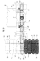
- an open-end spinning machine has a plurality of working or arranged side by side Spinning stations 10, which are arranged on one or both longitudinal sides of the open-end spinning machine 1.
- Each spinning station 10 is formed in the usual way and has a spinning element, for. B. a spinning rotor, the one Sliver 4 is supplied so that it is spun into a thread (not shown) in a known manner.
- the cans 43 have such a dimension that they overlap extend two adjacent spinning stations 10. For this reason it is envisaged that every second Spinning station 10a a can 43a of a first row of cans a and each intermediate spinning station 10b one Can 43b is assigned to a second row of cans b.
- a can group 430 consisting of a can 43a and a Kanne 43b
- the sliver 4 threatens to run out, a corresponding pulse to the control device of the Given open-end spinning machine 1, which then causes as soon as possible behind the two cans 43a and 43b in a third can row c a can 43c is provided as a reserve can in a waiting position.
- the can 43a or 43b, from which sliver 4 is continuously removed for spinning, runs out is then the sliver 4 from the can 43c into the corresponding feed device (not shown) by the outflow of the sliver 4 stopped spinning station 10a or 10b of such a spinning station pair introduced.
- FIG. 2 shows another one Embodiment in which a can storage unit composed of two can storage units 50, 51 is located on the line 30 5 is provided.
- Figure 2 shows schematically a part of a plant with a draw frame 30 and two spinning or twisting machines 11, 110, of which only a part of their longitudinal extent is shown.
- the route 30 has a filling head 31 as well Can memory 50, 51, which will be described in more detail later.
- the inlet 302 of the line 30 is for interaction with, for example, six round round cans 410 to 415 (sixfold doubling).
- the spinning or Twisting machines 11, 110 each have an end head 12 which is in the vicinity of a predetermined connecting path (Path 901 - shown in dashed lines) is arranged.
- the path 901 enters the exit of the route 30, so that can transport 2 can be positioned between the can stores 50, 51.
- the path 901 can e.g. B.
- Non-contact transmitters (not shown) be, e.g. Infrared devices with a corresponding non-contact receiver (not shown) work together on the can transport 2.
- a can storage is not in this embodiment of the spinning or twisting machine 11 or 110 assigned.
- Two branches (pathways) connected to path 901 each extend along machines 10, 110 902, 903), the two branches in the vicinity of the machines 50, 51 and parallel to one another and to the machine longitudinal directions run.
- the route 901 can, as indicated, be extended to include the route 30 with other machines or To connect machine sides. If necessary, these can also be machines of different types.
- a machine arrangement according to FIG. 2 can be controlled from the spinning or twisting machines 11, 110 by connecting each machine to route 30 via a signal line (not shown) and "delivery orders" sends to route 30.
- the route 30 forwards such delivery orders to the can transport means 2, e.g. B. if this is opposite the route 30 in a can receiving point.
- the can transport 2 itself can be provided with sufficient intelligence (computing capacity) to convert the "delivery orders" into "travel orders” and execute these driving orders accordingly. More details will be described later in detail.
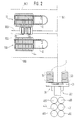
- FIG. 1 shows a delivery roller 14 of an open-end spinning machine 1 (see FIGS. 1 and 3), which is driven, for example, via an individual drive 140, but this type of drive does not matter, so that a common drive for several side by side located spinning stations 10 (see Figures 1 and 3) can be provided.
- a switching flag 850 which, when the delivery roller shaft 141 rotates, periodically into the area of a light barrier 851 between a light source 852 and a photocell 853.
- the photocell 853 is connected via a line 854 a control device 855 of the open-end spinning machine 1, which in turn via a data line 81 is connected to a control device 8, which will be discussed in more detail later.
- the control device 855 together with the light barrier 851 forms a measuring device. If namely a certain number of pulses has been emitted by the switch flag 850 - that of a certain length and thus corresponds to a certain consumption of the sliver 4 - so the control device 855 releases the open-end spinning machine 1 via the data line 81 in the control device 8 from a pulse from the control device 8 processed and understood as a request for a full can 43 or 44.
- the control device 8 can can be arranged on the can transport means 2 itself - as described above - or stationary - as later in connection will be explained with Figures 14 and 15.
- a further light barrier 856 between a light source 857 and Photocell 858 provided.
- the photocell 858 is in terms of tax with the machine-side control device 855 Connection which is either directly connected to the can transport means 2 or via the central one Control device 8 causes the actual can exchange at the spinning station 10 when that into the spinning station 10 incoming sliver 4 runs out.
- the can transport means 2, with which the can requirement indicator 85 can be connected, is located either on one of the machines installed in a system or on the way between these machines, e.g. a draw frame 30 and a spinning or twisting machine 11 or 110 or between one of these machines and a can storage (e.g. can magazine 600 or 601) which - as shown in FIGS. 14 and 15 - also independently can be arranged by these machines.
- a can storage e.g. can magazine 600 or 601 which - as shown in FIGS. 14 and 15 - also independently can be arranged by these machines.
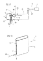
- the can requirement indicator 86 is shown in FIG. 22.
- the can requirement indicator 86 is designed as a sensor and gropes the contents of a jug, e.g. a flat can 44, and is connected via a line 860 to the machine Controller 855 (see Figure 21) connected.
- the can demand indicator 86 detects the can content, i.e. the inside of the jug, can determine the Flat can 44 on its narrow side a window 446, which is essentially in the embodiment shown extends over the entire height of the can and is closed by a transparent insert to prevent impairment prevent sliver placement or removal. If the sliver 4 the bottom of the window reached, the can requirement indicator 86 is addressed, which then takes the further measures - as described - triggers.
- the can requirement indicator 86 does not have to be movably mounted, in the exemplary embodiment shown it is arranged on the side of the can facing away from the operating side. This is illustrated in FIG. 22 by an arrow P 7 , which indicates the direction of delivery of a jug to its workplace.
- a small window at the lower end of the flat can 44 would suffice.
- an elongated window 446 is required, so that by changing the Height adjustment of the can requirement indicator 86 relative to the flat can 44, i.e. through vertical adjustment of the can requirement detector 86 along the window 446, the desired lead time can be selected.
- a window 446 is sufficient.
- can demand detectors can also be processed or processed on other slivers 4 Machines or devices are provided.
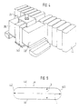
- the cans in which the sliver 4 is placed have is not a round profile, but are elongated (flat can 44). Your two long sides (side walls 440, 441) can thus serve as a guide, as will be described later. Furthermore, the cans 44 can be dimensioned such that only one per work or spinning row of spinning or twisting machine 11, 110 only row of cans must be provided (see row of cans a in Figure 1).
- the flat can 44 shown in FIG. 2 has two parallel side walls 440, 441, which are the can width Define B.
- the flat can 44 also has two end pieces 442, 443 which form the side walls 440, 441 connect with each other and define the can length L.
- 5 shows rounded end pieces 442, 443, but instead of being round, they also stand perpendicular to the side walls 440, 441 or be designed as a polygon can.
- the pitcher length L is significantly larger (e.g. three to four times larger) than the pitcher width B, which in the essentially corresponds to the width of a work or spinning station 10. In this way, i.e. through the essentially four times the width of the flat can, the capacity of the flat can is achieved Jug (flat jug 44) the capacity of a round jug commonly used in spinning or twisting machines equivalent.
- the capacity of a flat jug 44 should be the capacity of a round jug (z. B. can 43 of Figure 1) correspond to a diameter of 450 to 500 mm. If accepted as an example is that the diameter of a conventional round can is about 457 mm, then has a flat can 44 according to the figure 5 with a can width B of 230 mm and a can length L of 780 mm a slightly larger capacity than the round jug. In other words, the length (can length L) of the flat can 44 does not have to be twice that Round can diameter to give the same capacity.
- the height of the can is determined by the construction of the spinning or twisting machine frame given that the cans 43 and 44 must be placed under the spinning station.
- FIGS. 1 and 6 show, there is a can delivery point 500 of the can store 50 and the can delivery point 511 of the can storage 51 arranged close together and on the path 901 of the can transport means 2.
- the can transport means 2 has a can receiving part 20 and two end parts 21, 22. Each End part 21, 22 carries a post 210, 220, which in turn carry a beam 23, which acts as a guide rail serves for a can offset means 7.
- the can offset means 7 is movable in the longitudinal direction of the beam 23 and thereby deliverable to the individual flat cans 44 on the can transport means 2.
- the can offset means 7 comprises its own rail 710, which is perpendicular to the beam 23 and as a guide rail for a can slide 71 serves (see Figure 3).
- the can slide 71 of the can transport means 2 comprises a gripping means (not shown), which is caused by a movement parallel to the can's longitudinal extension and transversely to the direction of travel of the can transport means 2 pushes the flat cans 44 from the can transport means 2 into the can delivery point 500 on the route 30 and at the same time pulls a second flat can 44 from the can delivery point 511 onto the can transport means 2.
- Each end part 21, 22 of the can transport means 2 has wheels 24, which movements of the shown in Embodiment designed as a ground vehicle can transport means 2 perpendicular to the long side of the Flat cans 44 allows.
- the can transport means 2 has a drive (not shown) and possibly one Control that controls a steering system (not shown) for the wheels 24.
- pitches which is between two and twelve.
- FIG. 14 shows an embodiment of the can offset means 7 with the rail 710, on which a can slide 75 is slidably arranged, which in turn has two gripping means 726 and 727.
- the right jug flat jug 44
- the platforms 53 and 530 which are part of the can storage 50 and 51, respectively, are arranged according to FIG.
- both can storage 50 and 51 are designed as roller conveyors on which the empty or full Cans (e.g. flat cans 44) automatically into the dispensing point 501 or into the because of a corresponding inclination Can delivery point 511 slide.
- the can delivery point 500 and the can delivery point are naturally located 511 at different heights, so that this height difference at least in one of these places must be compensated when loading or unloading.
- the two can storage devices 50 and 51 serve cans that are not immediately needed to cache.
- a spinning or twisting machine 11, 110 e.g. an open-end spinning machine 1, or another textile machine, e.g. a circular knitting machine for the production of plush or carpet goods
- jug e.g. a flat jug 44 placed in the can storage 50 temporarily stored until the line 30 is able to fill this can.
- a newly filled can remains in the can storage 51 until it is processed or processed by the slivers 4 Machine or device is needed.
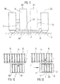
- FIG. 8 shows a linear arrangement of the can stores 50 and 51 across the path 901 of the can transport means 2, wherein a flat can 44 by an arcuate movement from or onto the can transport means 2 must be moved.
- the can transport means is located here - just like that in FIGS. 2 and 6 embodiment shown - in the middle plane between the two can stores 50 and 51, not however parallel to these, but in a direction perpendicular to the longitudinal extent of the two can stores 50 and 51 located level.
- FIG. 7 shows another linear arrangement of the can stores 50 and 51, but in contrast to that The embodiment shown in FIG. 8 parallel to path 901 of the can transport means 2 and transversely to the longitudinal extent the flat cans 44.
- the flat can 44 to be filled becomes the filling head 31 of the section 30 from the can store 50 fed from the same side, after which the filled flat jug 44 later in the can storage 51 is delivered.
- Such training requires that the can delivery point 500 and The can delivery point 511 is located at the opposite ends of the can store 5.
- the can offset means 7 see Figures 3 and 6) are divided into two partial offset means by a corresponding control are synchronized with each other.
- the can offset means 7 is arranged on the can transport means 2, but this is no mandatory requirement for changing the can, especially if the Can store 50, 51 according to FIG. 7 can also be a stationary arrangement of the one divided into two partial offset means Can offset means 7 can be very advantageous.
- a partial offset means serves to unload the can transport means 2, while the other partial offset means is used to load the can transport means 2.
- the two partial offset means also in one and to arrange the same working level transversely to the path of the can transport means 2.
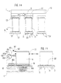
- FIG 9 shows such a device, as shown schematically in Figure 7, in more detail.
- the two Can stores 50 and 51 are each can offset means in the form of conveyor belts or chains 502 and 512 assigned that directly next to another conveyor belt or another conveyor chain 32 with the help are deflected by pulleys 503 or 513.
- the conveyor belt or chain 32 extends from Can store 5 up to near the filling head 31 of the line 30 and is deflected by deflection rollers 320.
- the Transport chain 32 drives a driver 321, which engages the flat can 44 and this into the area of Filling head 31 transported, where the flat can 44 by two arms 33 one designed as a traversing device Can offset means are taken over.
- the arms 33 can be pivoted back out of the area of the flat can 44, so that the flat can 44 is brought by the conveyor belt 32 into the traversing area of the line 30 can, and are also mutually movable and form a gripper to the flat can 44 firmly between them to be able to clamp.
- the traversing device is necessary because, in contrast to storage in round cans the sliver 4 is not evenly distributed in the flat can 44 by the storage head of the section 30 can.
- the transport chain 32 In order not to impair the traversing movement which is required for filling a flat can 44, the transport chain 32 from the traversing area of the route 30 to the basic position in which the driver 321 is located on the side of the can store 5 facing away from the route 30.
- a further transport chain 34 with a driver 341 is provided, which is guided by deflection rollers 340 is redirected.
- the deflection rollers 320 are arranged so that the driver 321 from the side facing away from the line 30 of the can store 5 for receiving a flat can 44 are brought into the immediate vicinity of the filling head 31 can, so that the flat can 44 can then be taken over by the arms 33.
- the deflection rollers 340 of the Transport chain 34 are arranged so that the flat can 44 through the driver 341, which is initially on the the side facing away from the can store 5 until it can be returned to the can store 5.
- the two transport chains 32 and 34 together form a can offset means for Delivery and removal of a flat can 44.
- the can store 5 has a horizontal can space so that the can delivery point 500 and the Can delivery point 511 are at the same level. That way, there is no need to either the can delivery point 500 or at the can delivery point 511 or at both of these points with the can transport means 2 to overcome height differences.
- the conveyor belts or chains 502 and 512 are formed as support elements in the embodiment shown and have no drivers like the transport chains 32 and 34, which only work as tension elements. For this reason, there are transport chains on both sides 32 and 34 roller conveyors 35 are arranged with a plurality of rollers 350 on which the flat can 44 glides well. Alternatively, it is also possible to provide driven rollers instead of conveyor belts or chains.
- Figure 10 shows a detail of Figure 9 in view B-B. As can be seen, are at the transitions between the conveyor belts or chains 502 and 512 of the can storage 50 and 51 and the conveyor chain 32 fillers 52 and 520 filling the intermediate space are provided in order to ensure that the flat cans at the transition from the can store 50 into the area of the transport chain 32 or at the transition from the area the transport chain 32 in the can storage 51 can not perform any tilting movements.
- the filled flat cans 44 are to the spinning or twisting machines 11, 110 (see Figure 2), e.g. B. to open-end spinning machines 1 (see Figure 1), to replace them with empty flat cans 44.
- spinning or twisting machines 11, 110 see Figure 2
- open-end spinning machines 1 see Figure 1
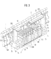
- Figure 3 shows an open-end spinning machine 1 twenty-three spinning stations 10 and a can transport 2 for transporting and exchanging flat cans 44 at the spinning stations 10.
- the can-receiving part 20 of the can transport means 2 is divided into compartments 201 by partitions 200 broken down, each compartment 201 for receiving a flat can 44 by moving the flat can 44 in its Longitudinal direction is suitable.
- the can offset means 7 is the individual compartments 201 by moving in the longitudinal direction of the bar 23 of the can receiving part 20 is deliverable.
- the flat cans 44 are guided by guides 130 and 131 near the upper and / or lower end of the Flat can 44 out.
- the can transport means 2 is selected by a system control, which will be discussed in more detail later Spinning station 10 performed, in which the flat can 44 is to be replaced.
- a suitable positioning system (Not shown here) the can transport means 2 is initially positioned in such a way that its empty compartment 201 is open the spinning station 10 is aligned at which the flat can 44 is to be replaced.
- the can offset means 7 is the empty compartment 201 of the can transport means 2, and the can slide 71 is directed towards the machine moves so that its gripper (not shown) can grip the empty can 44 to be replaced. With a movement of the can slide 71 away from the machine, the flat can 44 to be replaced is placed in the previously empty compartment 201 of the can transport means 2 is pulled (see FIG. 12).
- the can transport means 2 is then moved around a compartment filled with a full flat can 44 201 of the can transport means 10 to be aligned with the relevant spinning station 10.
- the can offset means 7 moved along the bar 23 in order to deliver the can offset means 7 to the newly introduced flat can 44.
- this full flat can 44 is then in the Operating position moved.
- the can transport means 2 can now be delivered to another selected spinning station 10, where the procedure is repeated, the empty compartment 201 of the can transport means 2 no longer being on the original one Place, but at the place of the last full flat can 44 delivered to the machine.
- the empty compartment 201 is moved step by step until all full flat cans 44 are in the Open-end spinning machine 1 have been introduced and by empty (or at least to be replaced) flat cans 44 have been replaced.
- the can transport means 2 is then moved back to the route 30.
- the can-receiving part 20 of the can transport means 2 does not need to be rigid with the end parts 21, 22 of the can transport means 2 to be connected. As indicated by double arrows 25 in FIG. 3, the part 20 also be adjustable in height relative to the end parts 21, 22, around the flat cans 44 at the same height from the part 20 in their loading or unloading position on the line 30 or the open-end spinning machine 1 or another Textile machine or devices - and of course in the opposite direction - to be able to move.
- the can transport means 2 can in principle be designed differently, e.g. as a gondola attached to one Rail (not shown) is movable. However, it is preferably designed as a ground vehicle that runs on rails or can also be moved without rails.
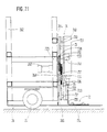
- FIGS. 4 and 11 show a can transport means 26 designed as a ground vehicle, which differs of the can transport means 2 formed in the figure.
- the can transport means 26 carries a can-receiving part 260 and two End parts 261 and 262.
- the can-receiving part 260 has a total of only two can positions 263 and 269, namely a can slot 269, which is normally occupied by a can 43 or 44 (full or empty) and a second can slot 263 (dashed), which can hold a can 43 or 44 (full or empty) is kept free.
- the two end parts 261, 262 are provided with wheels 24, of which at least one set is steerable is. Preferably, both sets of wheels are steerable, so that the can transport means 26 also transversely in both directions can be moved to the longitudinal axis of the received cans 43 or 44.
- End portions 261 and 262 included electric drives (shown in Figures 4 and 11). Furthermore, each end part carries 261 or 262 can offset means 70 and 700, which are only shown schematically in FIG. 11, but below in connection with the figures 18 to 21 are described in more detail.
- the two (partial) can offset means 70 and 700 are one behind the other at a distance the width of a can parking space 263, 269 and in two transverse to the path of the can transport means 26 movable levels movable. Both (partial) can offset means 70 and 700 can also be controlled independently of one another, as can be seen from the description below.
- the can transport means 26 is designed to carry out driving orders, the can transport means leaves the line 30 (see FIGS. 1 and 2) with a single full can 43 or 44 and a fixed one Path 901 to a predetermined spinning station 10 follows.
- the can exchange On arrival at the spinning station 10, where the can exchange is to be carried out, one can parking space 263 is empty, while the other can space 269 with one full can 43 or 44 is occupied.
- the can replacement by the can offset means 700 now takes place by first an empty can 43 or 44 from the relevant spinning station 10 (see FIG.
- the can transport means 26 After the can change has been carried out, the can transport means 26 returns to the route 30 by the exchange the empty can 43 or 44 for a new full can 43 or 44 and then replace it to get the next job.
- the vehicle control is provided with enough intelligence (computing capacity) in order to be able to execute a motion task without further information or communication with a host computer to require so that a continuous communication link between the host computer and the can transport eliminated.
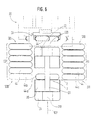
- FIGS. 18 to 21 It shows Figure 18 is a plan view of such a can offset means 700 together with the end pieces 443 of two flat cans 44th
- Each end piece 443 of a flat cans 44 is formed with two tabs 444 and one each as a bracket 445 Provide a header that interacts with the can offset means 700 as follows to be described in more detail. It is assumed that the can transport means 26 (FIG. 11) with the can offset means 700 (similar to FIG. 12) with respect to a predetermined spinning station 10 for exchanging flat cans 44 is positioned.
- the can transport means 26 has two can positions 263 and 269. For each can parking space 263 and 269 there is a separate can offset means on the can transport means 26 70 and 700 are provided, as indicated in FIG. 11, so that the loading and unloading process is carried out from the can transport means 26.
- the two can offset means 70 and 700 are arranged in mirror image to one another. With the help of the figures 18 to 20, only the can shifting means 700 will be described below because of the structure and function of its parts correspond exactly to the can offset means 70.
- a stepper motor the just like another motor 267 - which can also be designed as a stepper motor and its task will be explained later - is carried on a plate 268 of the end part 262.
- the engine 266, of which only a drive roller can be seen in FIG are also attached to the plate 268, deflected and thus held in engagement with the drive roller of the motor 266 is, with the two deflection wheels 733 a looping of over 180 ° comes about.
- the carrying carriage 73 can thus be moved from one end of the guide rails 730, 731 to the other end and back, i.e. in one direction (see arrow X) or in the opposite Direction (see arrow Y), are moved transversely to the longitudinal extent and direction of travel of the can transport means 26.
- the can offset means 700 has a gripping means 72 and a can slide designed as a carrier 74 on, which is designed as a trolley (back and forth) on the carrying carriage 73.
- the can slide 74 moves towards the open-end spinning machine 1 (FIG. 3) and in the other Direction (arrow Y) away from the machine.
- the second motor 267 is provided, which one drives endless toothed belt 737, which is deflected by means of deflection rollers 739 attached to the end part 262.
- the toothed belt 737 carries a driver 736, via which the can slide 74 is connected to the toothed belt 737 is.
- Two guide rollers 739 for the toothed belt 737 are also provided on the plate 268 for the toothed belt 737.
- the motor 267 becomes in addition to the motor 266 for the movement of the can pusher 74 in the direction of a the arrows X or Y driven so that the can slide 74 executes a relative movement to the carrying carriage 73.
- the can slide 74 can be moved to both ends of the carrying carriage 73, but does not project beyond it of his possible positions.
- the carrying carriage 73 can also be moved with respect to the can transport means 2, this can be one keep a certain distance from the open-end spinning machine 1 without the exchange process being affected.
- the drives shown via the toothed belts 732, 737 enable the drives to be firmly mounted on the end parts 261, 262 of the can transport means 2.
- the carrying carriage 73 carries an upper and a lower guide rail at different heights 730 or 731, on which the can slide 74 with its base plate 740 in a suitable manner, e.g. with the help of Casters, is slidably mounted.
- This base plate 710 carries a lifting device 721 which e.g. as a lifting cylinder is formed, between two bearing arms 741, which form a lifting column, by the lifting device 721 vertically movable base plate 710 are attached.
- the cross-translational movements of the carrying carriage 73 and the can slide 74 are completely separate from each other thanks to the separate motors 266 and 267.
- the drive of the can slide 74 compensate for the drive of the support carriage 73.
- Both inductive and mechanical limit switches for the can slide 74 and the carrying carriage can be used 73 may be provided.
- the entire control of the can transport means 26 is accommodated on this itself.
- the gripping means 72 has at its lower end an L-shaped yoke 720 (FIG. 20) and the one already mentioned Lifting device 721, which is attached to the can slide 71.
- the yoke 720 is connected to the Lifting device 721 connected, wherein a sliding guide 723 is provided to act on the gripping means 72 Torques directly (instead of via the lifting device 721) to the can slide 74.
- the yoke 720 is further provided with two protrusions 724 protruding upwards, each of which has a groove 725 ( Figure 19).
- a can e.g. flat cans 44
- the carrying carriage 73 extends on the rails 264 and 265 transversely to the can transport means 2 to the can transport 2 out.
- the can slide 74 travels transversely to the can transport means on this carrying carriage 73 2 out of the can transport means 2 in high speed up to shortly before the can and is thereby up to lowered to the floor.
- the can slide 74 then leads the last centimeters in slow motion and pushes the Can 44 easily under the open-end spinning machine 1.
- the yoke 720 with its projections 724 comes under the support bracket 445 at the lower end of the flat can 44 to be replaced. This makes the exact horizontal positioning of the gripping means 72 guaranteed.
- the gripping means 72 now moves upwards and slightly lifts the can.
- the support bracket 445 recorded in the grooves 725, after which a slight raising of the yoke 720 to "tilt" the flat cans 44 around its end piece 442 shown in Figure 18 (see Figure 5), that is, the flat can 44 slightly inclined for inclusion on the can transport means 26.
- Carrying carriage 73 and can slide 74 are now withdrawn (to the right according to FIG. 18), and the flat can 44 is thereby pulled out of its position under the spinning station 10 and onto the footprint 202 (can space 263 - see FIG. 11) of the can-receiving part 260 of the can transport means 26 posed.
- the slight inclination of the flat cans 44 when loading the can transport means 2 prevents one Collision between the bottom of the can and the edge of the can receiving portion 260 of the can transport 26th
- the carrying carriage 73 and the can slide 74 with the gripping means 72 move so far into the can transport means 26 in that the jug is finally centrally on the can transport 26. Then the jug lowered.
- the full can is not raised, but only pushed outwards by the can slide 74.
- the tabs 444 and bracket 445 are attached to the lower edge of the flat cans 44, while the gripping means 72 runs as close as possible to the footprint 202.
- the attachment on the jug serves as a bracket 445 and Cooperation with the corresponding gripping device 72.
- the cans do not need any special vertical cans under the spinning machine Direction.
- the frame of the open-end spinning machine 1 can with side guides (see Figures 3 and 4) with something Play be provided to tilt the flat cans 44 sideways during the movements described above to prevent.
- the jug e.g. flat jug 44
- wear-resistant sliding edges either on the jug or on the to provide respective pitches 263 and 269.
- Guides are provided on the open-end spinning machine 1 (see Figures 3 and 4), these are also expediently resistant to abrasion, e.g. made of polyethylene. The same applies to other can spaces outside the can transport means 26, i.e. not just at the Machine, but also in the can storage, too.
- the can offset means 700 is shown in FIGS. 18 to 21 for the can exchange to the left and have been described.
- the same can offset means can also be used to replace the can or to the right optional can exchange to the right or to the left can be provided.
- the sled 73 extended to the right, the movements of the can slide 74 and the gripping means already described 72 can be executed.
- the can offset means 70 or 700 can optionally be exchanged on the one or the other side are operated. But if the can offset means 70 or 700 is already a flat can 44 from the left (or from the right) on the can transport means 2 must also on the same side, that is a flat can 44 is dispensed to the left (or to the right).
- the transfer of a flat cans 44 to the open-end spinning machine 1 is done by moving the flat cans 44 executed from the footprint 202 in the direction transverse to the machine longitudinal plane.
- the footprint 202 in Can transport means 2 can be slightly larger than the footprint in the machine. This little difference in height is when loading the can transport means 2 by lifting the end piece 443 of the flat cans 44 by the Lifting device 721 overcome.
- Figure 21 shows the device shown in Figure 18 in its end position after the flat cans 44 on the Can transport 26 has been brought.
- Carriage 73 has the task of gripping means 72 up to the area of the bracket 445 of the flat cans 44 without bringing the can transport means 26 its distance from that under the spinning stations 10 arranged flat can 44 must be changed.
- the actual train movement then takes place by moving of the sled-shaped can slide 74 on the carrying carriage 73, but also the carrying carriage 73 in his basic position returns.
- the can storage spaces can storage spaces 263 and 269 of the can transport means 26 and the sliver 4 processing or processing machine and / or the pitches the can store 50, 51, i.e. the can delivery point 500 and the can delivery point 501. This should not exceed 100 mm, but should be less and if possible not exceed 40 mm. If all of the can spaces on the can transport means 26 and outside of it are on the same horizontal level, this is particularly advantageous for the can exchange or the can loading and unloading.
- the slight or no difference in height between the different pitches can be caused by a small distance A of the can-receiving part 260 of the can transport means 26 from the floor (see FIG 11) or by platforms 53 or 530 (see FIG. 17) at the same height as the top of the can-receiving Part 260 of the can transport means 26 can be reached.
- the can transport means 2 runs directly between a spinning station 10 and the route 30.
- the open-end spinning machine 1 or other machines e.g. Spinning or twisting machines 11 or 110
- the jug can be damaged for various reasons, so that its continued use in an automatic System is not desirable. Such a jug can e.g. because of a broken band in the company too still contain a considerable amount of sliver.
- the check can, of course, be carried out by the operator, but in the case of an automatic System can only carry out random checks, which is unsatisfactory. It is therefore better if the A can inspection station is arranged on the way of the can transport means 2 or 26, so that the inspection of the cans done on the way.
- the can transport means 2 can itself be equipped with a can test station (not shown) his.
- Suitable intermediate can storage devices can be used in the system for this purpose be provided as a buffer store, in which empty, full, to be checked or separated cans be stored.
- Examples of a can inspection station 6 are described below.
- the can testing station 6 is designed or has a can weighing device on, which has a plate 65, which is supported with the interposition of a spring 650 on the floor.
- the plate 65 is depressed, which is indicated in a display device 651 becomes.
- the pointer 652 of the display device 651 moves according to the weight of the can (e.g. flat can 44) along a scale 653, which is divided into two partial scales 653a and 653b.
- the partial scale 653 from the pointer 652 is scanned as long as the jug shows your target weight that it has in its empty state, the partial scale 653b swept over if this weight is exceeded due to tape residues in the can (e.g. flat can 44).
- the pointer 652 and the partial scale 653b form part of a circuit (see line 654) which a signal lamp 655 is connected.
- a rotating plate 66 is arranged, on which the can by means of a schematically indicated Greifsch728 can be turned off.
- the rotating plate 66 is in a suitable manner with a rotary drive 660, which can rotate the rotating plate 66.
- a sensor 661 is also provided, which suitably has the upper edge or another relevant area of the contour of the cans (flat cans 44) can be scanned and if there is a deviation from a target value the signal lamp 655 responds via a line 662.
- the Rotating plate 66 is set in rotation by means of the rotary drive 660.
- a lifting device can also be used for the rotating plate 66 or plate 65 so that each point of the can circumference is in the area of sensor 661 can reach.
- the Sensor 661 can be vertically movable so that the aforementioned lifting device for the rotary plate 66 or the plate 65 can be omitted.
- the display device 651 thus serves to display a non-empty jug while the sensor 661 responds. if the physical condition of the jug, in the embodiment shown the particularly important jug rim, is not is okay.
- FIG. 16 A different embodiment in which the can inspection station 6 is also used as a can weighing device is shown in Figure 16.
- the can 43 or 44 has a loose, relative to the Sidewalls of the jug and by the action of a rod 67 vertically movable from the outside, i.e. liftable bottom 45.
- the jug stands on a pedestal 531 which has an opening 532 through which protrudes through part of a rod 67, which projects into a coil 670 at its other end.
- the linkage 67 is part of a lifting device and is acted upon by a spring 671 such that the linkage 67 rests on the underside of the bottom 45 of the can 44 and seeks to lift it.
- a signal is generated in the coil 670, which, for example, a signal lamp (similar to 655 according to FIG. 15) for Lights up.
- Such a floor 45 which can be raised by the action of the outside, is also suitable for the storage free of warping Sliver 4 in the can 43 and 44 by means of a filling head 31 and the later distortion-free removal of Sliver 4 is an advantage.
- the methods and devices mentioned are not only between one or more draw frames 30, 30a, 36 or 36a and one or more spinning or twisting machines 11, 11a, 110, 110a, 111, 111a 112, 112a or an open-end spinning machine 1 are used or there can be installed, but also in connection with other textile machines that release slivers - e.g. a carding machine which also has a filling head - or process - e.g. a circular knitting machine, a ring or an air spinning machine.
- a carding machine which also has a filling head - or process - e.g. a circular knitting machine, a ring or an air spinning machine.
Landscapes
- Engineering & Computer Science (AREA)
- Mechanical Engineering (AREA)
- Textile Engineering (AREA)
- Spinning Or Twisting Of Yarns (AREA)
- Replacing, Conveying, And Pick-Finding For Filamentary Materials (AREA)
Applications Claiming Priority (5)
| Application Number | Priority Date | Filing Date | Title |
|---|---|---|---|
| DE19904015938 DE4015938A1 (de) | 1990-05-18 | 1990-05-18 | Spinnereianlage |
| DE4015938 | 1990-05-18 | ||
| DE4035439 | 1990-11-08 | ||
| DE19904035439 DE4035439A1 (de) | 1990-11-08 | 1990-11-08 | Verfahren und vorrichtung zum automatischen anlegen eines faserbandes an einer textilmaschine |
| PCT/DE1991/000410 WO1991018135A1 (de) | 1990-05-18 | 1991-05-17 | Verfahren und vorrichtung zum transportieren von kannen zwischen faserbänder be- oder verarbeitenden maschinen oder vorrichtungen |
Publications (3)
| Publication Number | Publication Date |
|---|---|
| EP0528907A1 EP0528907A1 (de) | 1993-03-03 |
| EP0528907B1 EP0528907B1 (de) | 1999-03-17 |
| EP0528907B2 true EP0528907B2 (de) | 2002-08-14 |
Family
ID=25893312
Family Applications (5)
| Application Number | Title | Priority Date | Filing Date |
|---|---|---|---|
| EP91909388A Expired - Lifetime EP0528907B2 (de) | 1990-05-18 | 1991-05-17 | Verfahren und vorrichtung zum transportieren von flachkannen zwischen faserbänder be- oder verarbeitenden maschinen oder vorrichtungen |
| EP95120117A Expired - Lifetime EP0709501B1 (de) | 1990-05-18 | 1991-05-17 | Verfahren zum Kannenwechsel zwischen einem Transportwagen für Flachkannen und einer OE-Spinnmaschine und Transportwagen zur Durchführung des Verfahrens |
| EP95106898A Expired - Lifetime EP0668380B1 (de) | 1990-05-18 | 1991-05-17 | Verfahren und Vorrichtung zum automatischen Anlegen eines Faserbandes an einer Textilmaschine |
| EP96119796A Expired - Lifetime EP0770717B1 (de) | 1990-05-18 | 1991-05-17 | Verfahren und Vorrichtung zum pneumatischen Aufnehmen und Zuführen eines Faserbandendes an eine OE-Spinnvorrichtung |
| EP91909136A Expired - Lifetime EP0528884B1 (de) | 1990-05-18 | 1991-05-17 | Verfahren und vorrichtung zum automatischen anlegen eines faserbandes an einer textilmaschine |
Family Applications After (4)
| Application Number | Title | Priority Date | Filing Date |
|---|---|---|---|
| EP95120117A Expired - Lifetime EP0709501B1 (de) | 1990-05-18 | 1991-05-17 | Verfahren zum Kannenwechsel zwischen einem Transportwagen für Flachkannen und einer OE-Spinnmaschine und Transportwagen zur Durchführung des Verfahrens |
| EP95106898A Expired - Lifetime EP0668380B1 (de) | 1990-05-18 | 1991-05-17 | Verfahren und Vorrichtung zum automatischen Anlegen eines Faserbandes an einer Textilmaschine |
| EP96119796A Expired - Lifetime EP0770717B1 (de) | 1990-05-18 | 1991-05-17 | Verfahren und Vorrichtung zum pneumatischen Aufnehmen und Zuführen eines Faserbandendes an eine OE-Spinnvorrichtung |
| EP91909136A Expired - Lifetime EP0528884B1 (de) | 1990-05-18 | 1991-05-17 | Verfahren und vorrichtung zum automatischen anlegen eines faserbandes an einer textilmaschine |
Country Status (8)
| Country | Link |
|---|---|
| US (1) | US5276947A (cs) |
| EP (5) | EP0528907B2 (cs) |
| JP (2) | JPH05508688A (cs) |
| BR (1) | BR9105752A (cs) |
| CS (1) | CS146291A3 (cs) |
| CZ (1) | CZ146091A3 (cs) |
| DE (5) | DE59108961D1 (cs) |
| WO (2) | WO1991018135A1 (cs) |
Families Citing this family (37)
| Publication number | Priority date | Publication date | Assignee | Title |
|---|---|---|---|---|
| DE4204967A1 (de) * | 1992-02-19 | 1993-08-26 | Truetzschler Gmbh & Co Kg | Vorrichtung zum transport mindestens einer kanne zwischen einer faserbandabliefernden spinnereimaschine und einer faserbandgespeisten spinnereimaschine |
| DE4230741C2 (de) * | 1992-09-14 | 2002-08-01 | Truetzschler Gmbh & Co Kg | Vorrichtung zum Abführen von Kannen für Textilfaserband, z. B. Baumwolle, Chemiefasern u. dgl. |
| DE4233357B4 (de) | 1992-10-05 | 2005-09-22 | Rieter Ingolstadt Spinnereimaschinenbau Ag | Verfahren zum Wechseln und Vorrichtung zum Magazinieren und Wechseln von Spinnkannen |
| CH688144A5 (de) * | 1992-10-08 | 1997-05-30 | Elitex Sp | Verfahren zum Austausch der Spinnbandbehaelter und Einrichtung zur Durchfuehrung des Verfahrens. |
| DE4234793C2 (de) * | 1992-10-15 | 1994-07-21 | Rieter Ingolstadt Spinnerei | Flachkanne |
| EP0604728B1 (de) * | 1992-12-23 | 1998-03-11 | Rieter Ingolstadt Spinnereimaschinenbau AG | Verfahren und Vorrichtung zum automatischen Anlegen eines Faserbandes |
| US5535581A (en) * | 1993-04-22 | 1996-07-16 | Murata Kikai Kabushiki Kaisha | Sliver cans exchanging system and sliver piecing system |
| IT1269612B (it) * | 1993-05-14 | 1997-04-08 | Truetzschler & Co | Procedimento e dispositivo per il riempimento di vasi con sezione trasversale allungata (vasi piatti) in una macchina per filanda, per esempio stiratoio |
| DE4407110B4 (de) * | 1993-05-14 | 2005-05-25 | Trützschler GmbH & Co KG | Verfahren und Vorrichtung zum Füllen von Kannen mit länglichem Querschnitt (Flachkannen) an einer Spinnereimaschine, z. B. Strecke |
| DE4323726A1 (de) * | 1993-07-15 | 1995-01-19 | Schlafhorst & Co W | Transportfahrzeug für Faserbandkannen |
| JPH07126938A (ja) * | 1993-10-26 | 1995-05-16 | Murata Mach Ltd | スライバ継ぎ方法 |
| DE4337115B4 (de) * | 1993-10-29 | 2007-03-22 | Rieter Ingolstadt Spinnereimaschinenbau Ag | Spinnereimaschine mit Zentrier- und Verriegelungseinheit für einen Kannen-Transportwagen |
| GB2287963B (en) * | 1994-04-02 | 1997-12-03 | Truetzschler Gmbh & Co Kg | Method and apparatus for filling sliver cans |
| US5634316A (en) * | 1994-04-02 | 1997-06-03 | Trutzschler Gmbh & Co. Kg | Method and apparatus for handling flat coiler cans before, during and after filling the cans by a sliver-producing textile machine |
| DE4411548B4 (de) * | 1994-04-02 | 2005-08-25 | Trützschler GmbH & Co KG | Vorrichtung zum Füllen von Kannen mit länglichem Querschnitt (Flachkannen) mit Faserband, z.B. Baumwolle, Chemiefasern u. dgl. |
| DE4427123A1 (de) * | 1994-07-30 | 1996-02-01 | Truetzschler Gmbh & Co Kg | Vorrichtung zum Transport mindestens einer Kanne zwischen einer faserbandabliefernden Spinnereimaschine, z. B. Karde, Strecke und einer faserbandgespeisten Spinnereimaschine, z. B. Strecke, Spinnmaschine |
| DE19521185A1 (de) * | 1995-06-10 | 1996-12-12 | Truetzschler Gmbh & Co Kg | Kannenfördersystem zwischen zwei Strecken |
| DE19525737A1 (de) * | 1995-07-14 | 1997-01-16 | Schlafhorst & Co W | Kannenspeicher für Rechteck-Spinnkannen an einer Kannenfüllstation |
| DE19632934A1 (de) * | 1996-08-16 | 1998-02-19 | Manfred Langen | Verfahren zum Austausch von Spinnkannen an einer Spinnmaschine |
| DE19713859C2 (de) * | 1997-04-04 | 2000-07-06 | Manfred Langen | Transport und Lagersystem für Spinnkannen |
| DE19719765A1 (de) * | 1997-05-10 | 1998-11-12 | Rieter Ingolstadt Spinnerei | Verfahren und Vorrichtung zum Transportieren einer Kannengruppe |
| DE19740661A1 (de) * | 1997-09-16 | 1999-03-18 | Manfred Langen | Spinnkannenstand |
| DE19819376A1 (de) * | 1998-04-30 | 1999-11-04 | Rieter Ingolstadt Spinnerei | Verfahren und Vorrichtung zum Zuführen und Abstellen von Kannen |
| DE10018184A1 (de) * | 2000-04-12 | 2001-10-25 | Evelyn Langen | Transport- und Lagersystem für Rechteck-Spinnkannen |
| DE10208806A1 (de) * | 2002-03-01 | 2003-09-11 | Rieter Ingolstadt Spinnerei | Verfahren und Vorrichtungen zum Befüllen und Austauschen von Flachkannen |
| DE602004022597D1 (de) * | 2004-06-30 | 2009-09-24 | Ministero Dell Istruzione Dell | Vorrichtung und verfahren zur einführung und vorförderung eines faserbands in ein spinnaggregat |
| DE102015102267A1 (de) * | 2015-02-18 | 2016-08-18 | Sipra Patententwicklungs- Und Beteiligungsgesellschaft Mbh | Bestückungsanordnung für eine Spinnstrickmaschine |
| DE102016214194A1 (de) * | 2016-08-02 | 2018-02-08 | Reinhard König | Transportvorrichtung für Vorratsbehälter für Faserband sowie Vorrichtung zur Herstellung von Garnen |
| CH713018A1 (de) * | 2016-10-07 | 2018-04-13 | Rieter Ag Maschf | Vorspinnmaschine sowie Verfahren zur Produktion von Vorgarn. |
| CN107345324A (zh) * | 2017-07-28 | 2017-11-14 | 贵州金州兔产业有限公司 | 一种新型兔毛纺纱机 |
| JP2020002478A (ja) * | 2018-06-25 | 2020-01-09 | 村田機械株式会社 | ケンス搬送車、繊維処理システム、空気紡績機、ケンス搬送方法、ケンス搬送プログラム、自走ケンス |
| DE102018118652A1 (de) * | 2018-08-01 | 2020-02-06 | Maschinenfabrik Rieter Ag | Spinnkanne mit einem Anzeigeelement zum Anzeigen von Eigenschaften des Fasermaterials |
| DE102019116279A1 (de) * | 2019-06-14 | 2020-12-17 | Saurer Spinning Solutions Gmbh & Co. Kg | Vorrichtung und Verfahren zum Einführen eines Faserbandes in eine Faserbandzuführeinrichtung einer Spinnstelle einer Spinnmaschine |
| CN110158168B (zh) * | 2019-06-25 | 2024-02-20 | 苏州金泉新材料股份有限公司 | 熔纺短纤维拉伸装置 |
| CN112053462B (zh) * | 2020-09-01 | 2022-07-01 | 北京谛测科技有限公司 | 络筒机数字纱线精密定长仪断电续记方法、装置及设备 |
| CN113443519B (zh) * | 2021-08-30 | 2021-11-16 | 成都辰迈科技有限公司 | 一种基于自适应功能的电缆长度计量设备及方法 |
| DE102021125996A1 (de) | 2021-10-07 | 2023-04-13 | Maschinenfabrik Rieter Ag | Verfahren und Handhabungseinrichtung zum Überführen eines Faserbandes von einer Spinnkanne in eine Arbeitsstelle |
Citations (5)
| Publication number | Priority date | Publication date | Assignee | Title |
|---|---|---|---|---|
| US5464436A (en) † | 1994-04-28 | 1995-11-07 | Lasermedics, Inc. | Method of performing laser therapy |
| US5632741A (en) † | 1995-01-20 | 1997-05-27 | Lucid Technologies, Inc. | Epilation system |
| US5697700A (en) † | 1997-01-17 | 1997-12-16 | Quarton Inc. | Handy laser pointer |
| JP2000064455A (ja) † | 1998-08-19 | 2000-02-29 | Sekisui House Ltd | 天井や壁等に用いる面材の補強構造 |
| US6370173B1 (en) † | 1999-07-26 | 2002-04-09 | Coronado Laser Co., L.L.C. | Heat sink for hand-held, high power laser |
Family Cites Families (27)
| Publication number | Priority date | Publication date | Assignee | Title |
|---|---|---|---|---|
| DE1044686B (de) * | 1954-06-08 | 1958-11-20 | Josef Pfenningsberg & Co Masch | Spinnkanne zur Vorlage an Direkt-Spinnmaschinen |
| US3443287A (en) * | 1962-02-09 | 1969-05-13 | Schubert & Salzer Maschinen | Can changing in strand material handling |
| CH589557A5 (cs) * | 1974-12-24 | 1977-07-15 | Rieter Ag Maschf | |
| DE2543621C2 (de) * | 1975-09-30 | 1984-11-22 | Zinser Textilmaschinen Gmbh, 7333 Ebersbach | Kannenwechseleinrichtung |
| DE2554915A1 (de) * | 1975-12-06 | 1977-06-08 | Krupp Gmbh | Arbeitsverfahren zur sicherstellung eines ausreichenden fasermaterial- vorrats fuer textilmaschinen und vorrichtung zur durchfuehrung des arbeitsverfahrens |
| DE2646313C2 (de) | 1976-10-14 | 1986-07-03 | W. Schlafhorst & Co, 4050 Mönchengladbach | Verfahren und Vorrichtung zum Auswechseln von Faserbandkannen |
| IT1158120B (it) * | 1981-06-19 | 1987-02-18 | Savio Spa | Procedimento ed apparecchiatura per il caricamento di una rastrelliera automatica ed il collegamento tra macchine tessili |
| DE3505495A1 (de) * | 1985-02-16 | 1986-08-21 | W. Schlafhorst & Co, 4050 Mönchengladbach | Verfahren und vorrichtung zum austauschen leerer kannen gegen mit faserband gefuellte kannen |
| US4735040A (en) * | 1985-04-30 | 1988-04-05 | Buro Patent Ag | Method of and apparatus for the automatic feeding of filled cans and the automatic removal of empty cans from the spinning units of a spinning machine |
| DE3524922C2 (de) * | 1985-07-12 | 1995-11-30 | Manfred Langen | Vorrichtung zum Austauschen leerer Kannen gegen gefüllte Kannen an einer Kannenstellplätze aufweisenden Spinnmaschine |
| DE3532172A1 (de) * | 1985-09-10 | 1987-03-12 | Truetzschler & Co | Vorrichtung zum automatischen transport mindestens einer kanne zwischen einer faserbandabliefernden spinnereimaschine und einer faserbandgespeisten spinnereimaschine |
| IN165584B (cs) * | 1985-09-10 | 1989-11-25 | Truetzschler & Co | |
| DE8606358U1 (de) * | 1986-03-08 | 1987-07-09 | Junghans Uhren Gmbh, 78713 Schramberg | Uhr, insbesondere mit Jahresuhren-Drehpendel |
| FR2610235A1 (fr) * | 1987-01-30 | 1988-08-05 | Iteca Sarl | Appareil de transport et de manutention de charges, comprenant un chariot sans conducteur a fourche de levage |
| CS277008B6 (en) | 1987-06-24 | 1992-11-18 | Schubert & Salzer Maschinen | Apparatus for stable fiber sliver automatic feeding |
| ES2032054T3 (es) * | 1988-03-22 | 1993-01-01 | S.P.A. Pettinatura Italiana | Procedimiento y aparato para encontrar uno de los extremos de una banda o mecha de fibra textil y para acoplarlo con los elementos de alimenacion de una maquina textil. |
| IT1220881B (it) * | 1988-05-02 | 1990-06-21 | Cerit Spa | Dispositivo di distribuzione automatica di nastro per macchine di filatura |
| IT1220906B (it) | 1988-06-29 | 1990-06-21 | Cerit Spa | Procedimento di presa e inserzione nastro in unita' di filatura a fibre libere e dispositivo adottante tale procedimento |
| DE3831637A1 (de) * | 1988-09-17 | 1990-04-05 | Schlafhorst & Co W | Aggregat aus einem oe-spinnautomaten und einer kannenwechselvorrichtung |
| DE3831638A1 (de) * | 1988-09-17 | 1990-03-22 | Schlafhorst & Co W | Kannentransportwagen |
| JP2584002B2 (ja) * | 1988-09-21 | 1997-02-19 | 株式会社豊田自動織機製作所 | 紡機の自動スライバ継ぎ方法 |
| DE8812622U1 (de) * | 1988-10-07 | 1990-02-08 | W. Schlafhorst & Co, 4050 Mönchengladbach | Vorrichtung zum Auswechseln der Faserbandkannen einer Spinnmaschine |
| DE3835188C1 (cs) * | 1988-10-15 | 1990-03-15 | Man Roland Druckmaschinen Ag, 6050 Offenbach, De | |
| DE3838318A1 (de) | 1988-11-11 | 1990-05-17 | Krupp Widia Gmbh | Werkzeugsystem |
| CH677782A5 (cs) * | 1988-11-28 | 1991-06-28 | Rieter Ag Maschf | |
| CS275197B2 (en) * | 1989-06-19 | 1992-02-19 | Kroupa Petr | Method of change automation, especially of non-circular cans with fibres |
| DE3928648A1 (de) * | 1989-08-30 | 1991-03-07 | Fritz Stahlecker | Anlage mit einer oder mehreren spinnmaschinen und mit wenigstens einem wechselwagen zum wechseln von kannen |
-
1990
- 1990-05-17 US US07/807,855 patent/US5276947A/en not_active Expired - Lifetime
-
1991
- 1991-05-17 DE DE59108961T patent/DE59108961D1/de not_active Expired - Fee Related
- 1991-05-17 EP EP91909388A patent/EP0528907B2/de not_active Expired - Lifetime
- 1991-05-17 WO PCT/DE1991/000410 patent/WO1991018135A1/de not_active Ceased
- 1991-05-17 WO PCT/DE1991/000409 patent/WO1991018134A1/de not_active Ceased
- 1991-05-17 DE DE59108036T patent/DE59108036D1/de not_active Expired - Fee Related
- 1991-05-17 JP JP91508725A patent/JPH05508688A/ja active Pending
- 1991-05-17 DE DE59109242T patent/DE59109242D1/de not_active Expired - Fee Related
- 1991-05-17 EP EP95120117A patent/EP0709501B1/de not_active Expired - Lifetime
- 1991-05-17 JP JP50892991A patent/JP3521085B2/ja not_active Expired - Fee Related
- 1991-05-17 CS CS911462A patent/CS146291A3/cs unknown
- 1991-05-17 DE DE59109248T patent/DE59109248D1/de not_active Expired - Fee Related
- 1991-05-17 EP EP95106898A patent/EP0668380B1/de not_active Expired - Lifetime
- 1991-05-17 BR BR919105752A patent/BR9105752A/pt unknown
- 1991-05-17 EP EP96119796A patent/EP0770717B1/de not_active Expired - Lifetime
- 1991-05-17 DE DE59109111T patent/DE59109111D1/de not_active Expired - Fee Related
- 1991-05-17 EP EP91909136A patent/EP0528884B1/de not_active Expired - Lifetime
- 1991-05-17 CZ CS911460A patent/CZ146091A3/cs unknown
Patent Citations (5)
| Publication number | Priority date | Publication date | Assignee | Title |
|---|---|---|---|---|
| US5464436A (en) † | 1994-04-28 | 1995-11-07 | Lasermedics, Inc. | Method of performing laser therapy |
| US5632741A (en) † | 1995-01-20 | 1997-05-27 | Lucid Technologies, Inc. | Epilation system |
| US5697700A (en) † | 1997-01-17 | 1997-12-16 | Quarton Inc. | Handy laser pointer |
| JP2000064455A (ja) † | 1998-08-19 | 2000-02-29 | Sekisui House Ltd | 天井や壁等に用いる面材の補強構造 |
| US6370173B1 (en) † | 1999-07-26 | 2002-04-09 | Coronado Laser Co., L.L.C. | Heat sink for hand-held, high power laser |
Also Published As
| Publication number | Publication date |
|---|---|
| EP0770717A3 (de) | 1997-08-13 |
| DE59109242D1 (de) | 2002-11-07 |
| EP0668380A3 (de) | 1995-11-02 |
| DE59109111D1 (de) | 1999-04-22 |
| EP0770717A2 (de) | 1997-05-02 |
| CZ146091A3 (en) | 1993-12-15 |
| JPH05501739A (ja) | 1993-04-02 |
| DE59109248D1 (de) | 2003-04-24 |
| CS146291A3 (en) | 1992-02-19 |
| BR9105752A (pt) | 1992-05-19 |
| EP0528907B1 (de) | 1999-03-17 |
| EP0709501A2 (de) | 1996-05-01 |
| WO1991018135A1 (de) | 1991-11-28 |
| EP0668380A2 (de) | 1995-08-23 |
| EP0668380B1 (de) | 1998-04-01 |
| EP0709501B1 (de) | 2002-10-02 |
| EP0528884A1 (de) | 1993-03-03 |
| JPH05508688A (ja) | 1993-12-02 |
| EP0770717B1 (de) | 2003-03-19 |
| DE59108961D1 (de) | 1998-05-07 |
| JP3521085B2 (ja) | 2004-04-19 |
| EP0528884B1 (de) | 1996-07-24 |
| WO1991018134A1 (de) | 1991-11-28 |
| EP0709501A3 (de) | 1996-07-31 |
| DE59108036D1 (de) | 1996-08-29 |
| EP0528907A1 (de) | 1993-03-03 |
| US5276947A (en) | 1994-01-11 |
Similar Documents
| Publication | Publication Date | Title |
|---|---|---|
| EP0528907B2 (de) | Verfahren und vorrichtung zum transportieren von flachkannen zwischen faserbänder be- oder verarbeitenden maschinen oder vorrichtungen | |
| DE4018088B4 (de) | Verfahren und Vorrichtung zum fortlaufenden Wechsel der Faserbandkannen in einem Maschinenverbund zwischen einer faserbandabliefernden Maschine und einer faserbandverbrauchenden Maschine | |
| EP0062063B1 (de) | Spinnmaschine, insbesondere ringspinnmaschine | |
| EP0404875B1 (de) | Synchron-Endlosförderer an einer Spinnmaschine | |
| DE2138926B2 (de) | Einrichtung zum selbsttätigen gruppenweisen Transportieren und Speichern von Kopsen | |
| DE102013013019B4 (de) | Verfahren zum Betreiben einer Fertigungsanlage, Lagersystem mit einem Kettentrieb und Fahrzeug mit einem Lagersystem | |
| DE3706871C2 (de) | Vorrichtung zum Abnehmen von Kreuzspulen oder dgl. | |
| DE3505494A1 (de) | Verfahren und vorrichtung zum austauschen leerer kannen gegen gefuellte kannen | |
| CH662586A5 (de) | Spinnanlage zur herstellung von garn aus vorgarn. | |
| DE102006012484A1 (de) | Vorrichtung in einer Spinnerei zum Transportieren einer kannenlosen Faserbandpackung | |
| EP0916614B1 (de) | Hülsenmagazin für eine Kreuzspulen herstellende Textilmaschine | |
| DE3518906C2 (de) | Kopsladevorrichtung in einer Kopstransportvorrichtung für den Kopstransport von einer Spinnmaschine zu einem Spulautomaten | |
| DE4323726A1 (de) | Transportfahrzeug für Faserbandkannen | |
| EP0198260B1 (de) | Verfahren und Vorrichtung zum Transport und zur Lagerung von Spulen, insbesondere zur Entsorgung von Spinnautomaten oder dergleichen | |
| DE29620792U1 (de) | Handhabungssystem für Filamentspulen oder Doffs | |
| DE2410408C2 (de) | Vorrichtung zum Auswechseln voller Spulen gegen leere Spulenkörper bei Steck- bzw. Zwirnmaschinen | |
| DE4015938A1 (de) | Spinnereianlage | |
| EP0514321B1 (de) | Einrichtung zum Transportieren und Handhaben von Schussfaden-Vorratsspulen sowie zum Zuführen derselben an Spulengestelle von Webmaschinen und Verfahren zum Betrieb der Einrichtung | |
| EP0643666A1 (de) | Elektrohängebahn mit spulenübergabe | |
| EP0311016B1 (de) | Anordnung zur automatischen Ver- und Entsorgung eines technischen Bedienbereiches in der Ringspinnerei und -zwirnerei mit Spulen, vorzugsweise Vorgarnspulen | |
| DE3942492A1 (de) | Palettiervorrichtung fuer spulen | |
| EP0360149A1 (de) | Verfahren und Vorrichtung zum automatischen Austauschen von Hülsen an einem Flyer | |
| DE19702163A1 (de) | Verfahren und Vorrichtung zum Transportieren voller Vorgarnspulen bzw. leerer Vorgarnhülsen | |
| EP0525448B1 (de) | Kannentransportwagen zum automatischen Kannenwechsel | |
| DE3246463A1 (de) | Bediengeraet, insbesondere fadenansetzgeraet fuer eine ringspinnmaschine |
Legal Events
| Date | Code | Title | Description |
|---|---|---|---|
| ITCL | It: translation for ep claims filed |
Representative=s name: ZINI MARANESI |
|
| PUAI | Public reference made under article 153(3) epc to a published international application that has entered the european phase |
Free format text: ORIGINAL CODE: 0009012 |
|
| 17P | Request for examination filed |
Effective date: 19920321 |
|
| AK | Designated contracting states |
Kind code of ref document: A1 Designated state(s): DE GB IT |
|
| 17Q | First examination report despatched |
Effective date: 19941007 |
|
| GRAG | Despatch of communication of intention to grant |
Free format text: ORIGINAL CODE: EPIDOS AGRA |
|
| GRAG | Despatch of communication of intention to grant |
Free format text: ORIGINAL CODE: EPIDOS AGRA |
|
| GRAH | Despatch of communication of intention to grant a patent |
Free format text: ORIGINAL CODE: EPIDOS IGRA |
|
| GRAH | Despatch of communication of intention to grant a patent |
Free format text: ORIGINAL CODE: EPIDOS IGRA |
|
| GRAA | (expected) grant |
Free format text: ORIGINAL CODE: 0009210 |
|
| RAP1 | Party data changed (applicant data changed or rights of an application transferred) |
Owner name: RIETER INGOLSTADT SPINNEREIMASCHINENBAU AG |
|
| AK | Designated contracting states |
Kind code of ref document: B1 Designated state(s): DE GB IT |
|
| PG25 | Lapsed in a contracting state [announced via postgrant information from national office to epo] |
Ref country code: GB Free format text: LAPSE BECAUSE OF NON-PAYMENT OF DUE FEES Effective date: 19990317 |
|
| REF | Corresponds to: |
Ref document number: 59109111 Country of ref document: DE Date of ref document: 19990422 |
|
| ITF | It: translation for a ep patent filed | ||
| GBV | Gb: ep patent (uk) treated as always having been void in accordance with gb section 77(7)/1977 [no translation filed] |
Effective date: 19990317 |
|
| PLAV | Examination of admissibility of opposition |
Free format text: ORIGINAL CODE: EPIDOS OPEX |
|
| PLBQ | Unpublished change to opponent data |
Free format text: ORIGINAL CODE: EPIDOS OPPO |
|
| PLAV | Examination of admissibility of opposition |
Free format text: ORIGINAL CODE: EPIDOS OPEX |
|
| PLBI | Opposition filed |
Free format text: ORIGINAL CODE: 0009260 |
|
| PLBF | Reply of patent proprietor to notice(s) of opposition |
Free format text: ORIGINAL CODE: EPIDOS OBSO |
|
| 26 | Opposition filed |
Opponent name: TRUETZSCHLER GMBH & CO. KG Effective date: 19991124 |
|
| PLBF | Reply of patent proprietor to notice(s) of opposition |
Free format text: ORIGINAL CODE: EPIDOS OBSO |
|
| PLBF | Reply of patent proprietor to notice(s) of opposition |
Free format text: ORIGINAL CODE: EPIDOS OBSO |
|
| PLBF | Reply of patent proprietor to notice(s) of opposition |
Free format text: ORIGINAL CODE: EPIDOS OBSO |
|
| PLAW | Interlocutory decision in opposition |
Free format text: ORIGINAL CODE: EPIDOS IDOP |
|
| PLAW | Interlocutory decision in opposition |
Free format text: ORIGINAL CODE: EPIDOS IDOP |
|
| PUAH | Patent maintained in amended form |
Free format text: ORIGINAL CODE: 0009272 |
|
| STAA | Information on the status of an ep patent application or granted ep patent |
Free format text: STATUS: PATENT MAINTAINED AS AMENDED |
|
| 27A | Patent maintained in amended form |
Effective date: 20020814 |
|
| AK | Designated contracting states |
Kind code of ref document: B2 Designated state(s): DE GB IT |
|
| PG25 | Lapsed in a contracting state [announced via postgrant information from national office to epo] |
Ref country code: IT Free format text: LAPSE BECAUSE OF NON-PAYMENT OF DUE FEES;WARNING: LAPSES OF ITALIAN PATENTS WITH EFFECTIVE DATE BEFORE 2007 MAY HAVE OCCURRED AT ANY TIME BEFORE 2007. THE CORRECT EFFECTIVE DATE MAY BE DIFFERENT FROM THE ONE RECORDED. Effective date: 20050517 |
|
| PGFP | Annual fee paid to national office [announced via postgrant information from national office to epo] |
Ref country code: DE Payment date: 20060707 Year of fee payment: 16 |
|
| PG25 | Lapsed in a contracting state [announced via postgrant information from national office to epo] |
Ref country code: DE Free format text: LAPSE BECAUSE OF NON-PAYMENT OF DUE FEES Effective date: 20071201 |