EP0529538B1 - Dispositif d'avancement de feuilles et système de formation d'images - Google Patents
Dispositif d'avancement de feuilles et système de formation d'images Download PDFInfo
- Publication number
- EP0529538B1 EP0529538B1 EP92114325A EP92114325A EP0529538B1 EP 0529538 B1 EP0529538 B1 EP 0529538B1 EP 92114325 A EP92114325 A EP 92114325A EP 92114325 A EP92114325 A EP 92114325A EP 0529538 B1 EP0529538 B1 EP 0529538B1
- Authority
- EP
- European Patent Office
- Prior art keywords
- sheet
- feeding means
- feeding
- roller
- recording
- Prior art date
- Legal status (The legal status is an assumption and is not a legal conclusion. Google has not performed a legal analysis and makes no representation as to the accuracy of the status listed.)
- Expired - Lifetime
Links
Images


Classifications
-
- B—PERFORMING OPERATIONS; TRANSPORTING
- B65—CONVEYING; PACKING; STORING; HANDLING THIN OR FILAMENTARY MATERIAL
- B65H—HANDLING THIN OR FILAMENTARY MATERIAL, e.g. SHEETS, WEBS, CABLES
- B65H9/00—Registering, e.g. orientating, articles; Devices therefor
- B65H9/004—Deskewing sheet by abutting against a stop, i.e. producing a buckling of the sheet
- B65H9/008—Deskewing sheet by abutting against a stop, i.e. producing a buckling of the sheet the stop being formed by reversing the forwarding means
-
- B—PERFORMING OPERATIONS; TRANSPORTING
- B65—CONVEYING; PACKING; STORING; HANDLING THIN OR FILAMENTARY MATERIAL
- B65H—HANDLING THIN OR FILAMENTARY MATERIAL, e.g. SHEETS, WEBS, CABLES
- B65H5/00—Feeding articles separated from piles; Feeding articles to machines
- B65H5/06—Feeding articles separated from piles; Feeding articles to machines by rollers or balls, e.g. between rollers
- B65H5/062—Feeding articles separated from piles; Feeding articles to machines by rollers or balls, e.g. between rollers between rollers or balls
-
- B—PERFORMING OPERATIONS; TRANSPORTING
- B65—CONVEYING; PACKING; STORING; HANDLING THIN OR FILAMENTARY MATERIAL
- B65H—HANDLING THIN OR FILAMENTARY MATERIAL, e.g. SHEETS, WEBS, CABLES
- B65H7/00—Controlling article feeding, separating, pile-advancing, or associated apparatus, to take account of incorrect feeding, absence of articles, or presence of faulty articles
- B65H7/02—Controlling article feeding, separating, pile-advancing, or associated apparatus, to take account of incorrect feeding, absence of articles, or presence of faulty articles by feelers or detectors
- B65H7/06—Controlling article feeding, separating, pile-advancing, or associated apparatus, to take account of incorrect feeding, absence of articles, or presence of faulty articles by feelers or detectors responsive to presence of faulty articles or incorrect separation or feed
- B65H7/08—Controlling article feeding, separating, pile-advancing, or associated apparatus, to take account of incorrect feeding, absence of articles, or presence of faulty articles by feelers or detectors responsive to presence of faulty articles or incorrect separation or feed responsive to incorrect front register
-
- B—PERFORMING OPERATIONS; TRANSPORTING
- B65—CONVEYING; PACKING; STORING; HANDLING THIN OR FILAMENTARY MATERIAL
- B65H—HANDLING THIN OR FILAMENTARY MATERIAL, e.g. SHEETS, WEBS, CABLES
- B65H9/00—Registering, e.g. orientating, articles; Devices therefor
- B65H9/10—Pusher and like movable registers; Pusher or gripper devices which move articles into registered position
- B65H9/103—Pusher and like movable registers; Pusher or gripper devices which move articles into registered position acting by friction or suction on the article for pushing or pulling it into registered position, e.g. against a stop
- B65H9/106—Pusher and like movable registers; Pusher or gripper devices which move articles into registered position acting by friction or suction on the article for pushing or pulling it into registered position, e.g. against a stop using rotary driven elements as part acting on the article
-
- B—PERFORMING OPERATIONS; TRANSPORTING
- B65—CONVEYING; PACKING; STORING; HANDLING THIN OR FILAMENTARY MATERIAL
- B65H—HANDLING THIN OR FILAMENTARY MATERIAL, e.g. SHEETS, WEBS, CABLES
- B65H2301/00—Handling processes for sheets or webs
- B65H2301/30—Orientation, displacement, position of the handled material
- B65H2301/33—Modifying, selecting, changing orientation
- B65H2301/331—Skewing, correcting skew, i.e. changing slightly orientation of material
-
- B—PERFORMING OPERATIONS; TRANSPORTING
- B65—CONVEYING; PACKING; STORING; HANDLING THIN OR FILAMENTARY MATERIAL
- B65H—HANDLING THIN OR FILAMENTARY MATERIAL, e.g. SHEETS, WEBS, CABLES
- B65H2403/00—Power transmission; Driving means
- B65H2403/40—Toothed gearings
-
- B—PERFORMING OPERATIONS; TRANSPORTING
- B65—CONVEYING; PACKING; STORING; HANDLING THIN OR FILAMENTARY MATERIAL
- B65H—HANDLING THIN OR FILAMENTARY MATERIAL, e.g. SHEETS, WEBS, CABLES
- B65H2511/00—Dimensions; Position; Numbers; Identification; Occurrences
- B65H2511/10—Size; Dimensions
- B65H2511/13—Thickness
-
- B—PERFORMING OPERATIONS; TRANSPORTING
- B65—CONVEYING; PACKING; STORING; HANDLING THIN OR FILAMENTARY MATERIAL
- B65H—HANDLING THIN OR FILAMENTARY MATERIAL, e.g. SHEETS, WEBS, CABLES
- B65H2511/00—Dimensions; Position; Numbers; Identification; Occurrences
- B65H2511/20—Location in space
-
- B—PERFORMING OPERATIONS; TRANSPORTING
- B65—CONVEYING; PACKING; STORING; HANDLING THIN OR FILAMENTARY MATERIAL
- B65H—HANDLING THIN OR FILAMENTARY MATERIAL, e.g. SHEETS, WEBS, CABLES
- B65H2511/00—Dimensions; Position; Numbers; Identification; Occurrences
- B65H2511/20—Location in space
- B65H2511/22—Distance
-
- B—PERFORMING OPERATIONS; TRANSPORTING
- B65—CONVEYING; PACKING; STORING; HANDLING THIN OR FILAMENTARY MATERIAL
- B65H—HANDLING THIN OR FILAMENTARY MATERIAL, e.g. SHEETS, WEBS, CABLES
- B65H2511/00—Dimensions; Position; Numbers; Identification; Occurrences
- B65H2511/50—Occurence
- B65H2511/51—Presence
- B65H2511/514—Particular portion of element
-
- B—PERFORMING OPERATIONS; TRANSPORTING
- B65—CONVEYING; PACKING; STORING; HANDLING THIN OR FILAMENTARY MATERIAL
- B65H—HANDLING THIN OR FILAMENTARY MATERIAL, e.g. SHEETS, WEBS, CABLES
- B65H2513/00—Dynamic entities; Timing aspects
- B65H2513/10—Speed
-
- B—PERFORMING OPERATIONS; TRANSPORTING
- B65—CONVEYING; PACKING; STORING; HANDLING THIN OR FILAMENTARY MATERIAL
- B65H—HANDLING THIN OR FILAMENTARY MATERIAL, e.g. SHEETS, WEBS, CABLES
- B65H2513/00—Dynamic entities; Timing aspects
- B65H2513/40—Movement
- B65H2513/41—Direction of movement
-
- B—PERFORMING OPERATIONS; TRANSPORTING
- B65—CONVEYING; PACKING; STORING; HANDLING THIN OR FILAMENTARY MATERIAL
- B65H—HANDLING THIN OR FILAMENTARY MATERIAL, e.g. SHEETS, WEBS, CABLES
- B65H2513/00—Dynamic entities; Timing aspects
- B65H2513/40—Movement
- B65H2513/41—Direction of movement
- B65H2513/412—Direction of rotation of motor powering the handling device
-
- B—PERFORMING OPERATIONS; TRANSPORTING
- B65—CONVEYING; PACKING; STORING; HANDLING THIN OR FILAMENTARY MATERIAL
- B65H—HANDLING THIN OR FILAMENTARY MATERIAL, e.g. SHEETS, WEBS, CABLES
- B65H2701/00—Handled material; Storage means
- B65H2701/10—Handled articles or webs
- B65H2701/13—Parts concerned of the handled material
- B65H2701/131—Edges
- B65H2701/1311—Edges leading edge
Definitions
- the present invention relates to a sheet feeding apparatus according to the preamble portion of claim 1, for feeding a sheet (normal sheet, cut sheet, print sheet, transfer sheet, photosensitive sheet, electrostatic recording sheet, printing sheet, OHP sheet, envelope, post card, original and the like), whilst preventing the skew feed of the sheet to a sheet processing station such as a printing station, image forming station, exposure station, working station and the like in an image forming system and other various sheet using devices such as a recording system (printer), copying machine, facsimile and the like as an information output equipment such as a word processor, computer and the like.
- the invention further relates to an image forming system using such sheet feeding apparatus.
- the sheet feeding means comprises a first sheet feeding means for feeding a sheet to a sheet processing station, and a second sheet feeding means including a pair of urgingly contacted rollers disposed between the first sheet feeding means and the sheet processing station.
- the sheet feeding means is so designed that a leading end of the sheet is abutted against a nip between the paired rollers of the second sheet feeding means now stopped by the normal rotation of the first sheet feeding means, and that a further normal rotation of the first sheet feeding means forms a predetermined loop in the sheet between the first and second sheet feeding means against the resilience of the sheet.
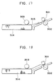
- the reference numeral 303 denotes a sheet supply roller
- 304 denotes a sheet stacker
- 305 denotes a recording medium
- 301 denotes a convey roller
- 302 denotes a driven roller.
- the sheet supply roller 303 is stopped while abutting against the sheet stacker 304, and then, the convey roller 301 is rotated reversely, thereby returning the leading end of the recording medium 305 to a position upstream of the nip between the convey roller 301 and the driven roller 302 (Figs. 18 and 19).
- the leading end of the recording medium is returned toward the upstream side from the nip between the convey roller 301 and the driven roller 302, and then, is abutted against the nip, thereby preventing the skew feed of the recording medium.
- the skew feed preventing ability is highly ensured in case of the cut sheet and the like a thickness of which is uniformly controlled, regarding sheets having no uniform thickness such as envelopes folded several times over and having different thickness folded portions, as shown in Fig.
- this feeding method causes skew feed of the sheet more noticeably than in the case where the sheet is directly forwarded without returning it toward the upstream side.
- the document EP-A-0 418 515 discloses a sheet feeding apparatus which comprises a single motor driving a first feeding means via a non-reversing clutch, and a second feeding means.
- the motor drives the first and second feeding means in a sheet advancing direction until the leading edge of the sheet is advanced into and past a nip of the second feeding means.
- the motor is then reversed so that the second feeding means retracts the sheet. Since the first feeding means is not driven in the reverse direction due to the provision of the non-reversing clutch, the sheet bends to form a loop between the first and the second feeding means. This loop tends to align the leading edge of the sheet with the nip, whereupon the motor is reversed again to feed the aligned sheet to the printing position.
- the document JP-A-62 259 944 which forms the preamble portion of claim 1, discloses a sheet feeding apparatus which comprises a first feeding means for feeding a sheet and a second feeding means disposed at a downstream side of the first feeding means for pinching and feeding the sheet.
- the first and second feeding means are controlled such that the sheet is fed by the first feeding means in a predetermined direction until it abuts against the second feeding means and bends to form a loop. Then both the first and second feeding means further feed the sheet until it reaches a sensor.
- both the first and second feeding means are reversed feeding the sheet back to the first feeding means, whereupon the same operation as that set forth above is repeated until the sheet is no longer skew fed (first mode). If the sheet is fed normally until it reaches the sensor for the first time, it is further fed by the first and second feeding means in the predetermined direction to an image forming means (second mode).
- the object of the present invention is to further develop the sheet feeding apparatus and the image forming system, respectively, according to the document JP-A-62 259 944 to the effect that the sheet feeding apparatus is less bulky, whilst the skew feeding of sheets is reliably prevented.
- the sheet feeding apparatus is provided with an urging means adapted to urge the sheet against the first feeding means such that the first feeding means allows the sheet returned in the reverse direction by the second feeding means to move through between the first feeding means and the urging means in the reverse direction, whilst the first feeding means and the urging means afford a frictional resistance to the sheet without flexing it.
- the sheet feeding apparatus as a whole can be kept small-sized since, besides the space for the sheet feeding path as such, no additional space is required between the first and second feeding means.
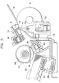
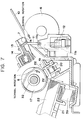
- Fig. 1 is a schematic elevational sectional view of a main portion of a recording system into which a sheet feeding apparatus according to the present invention is incorporated.
- An ink jet recording head 1 is mounted on a carriage 2.
- the carriage 2 is shifted in a main scanning direction perpendicular to a plane of Fig. 1 along a carriage shaft 3, the recording head 1 is moved for the main scan.
- An ink tank 4 serves to reserve ink which is supplied to the recording head 1 via an ink pipe 5.
- a paper guide (platen plate) 10 serves to define a position (printing station or sheet processing station) in which an image is printed or recorded on a recording sheet by the recording head 1.
- the recording head 1 is disposed in confronting relation to the paper guide with a small gap therebetween and is moved along a surface of the paper guide.
- a sheet stacker 21 is arranged in an inclined relation so that it is inclined downwardly and forwardly. The sheet stacker is normally biased upwardly by a spring 39. Recording sheets 22 are rested and stacked on the sheet stacker 21.
- a semi-circular sheet supply roller (first sheet feeding means) 17 is fixedly mounted on a sheet supply roller shaft 32.
- Idle rollers 18 are disposed on both sides of the sheet supply roller 17 and are idly mounted on the sheet supply roller shaft 32.
- the diameters of the idle rollers 18 are smaller than a diameter of the sheet supply roller 17.
- a friction member (friction pad) 19 is disposed below the sheet supply roller 17 and is always biased upwardly by a spring 20 so that it is urged against the idle rollers 18 or a cylindrical portion of the semi-circular sheet supply roller 17.
- a pair of rollers 6, 7 which are urged against each other constitute a second sheet feeding means.
- the lower large roller 6 acts as a driving roller (referred to as “convey roller” hereinafter) and the upper small roller 7 acts as a driven roller.
- the upper driven roller 7 is held by a holder member 13 which is biased toward the lower convey roller 6 by a spring 14 so that the driven roller 7 is urged against the convey roller 6.
- a pair of ejector rollers comprise a lower driving roller 8 and an upper driven roller 9.
- the upper driven roller 9 is held by a holder member 15 which is biased toward the lower driving roller 8 by a spring 16 so that the upper driven roller 9 is urged against the lower driving roller 8.
- the reference numeral 23 denotes an ejection sheet stacker.
- a sensor lever 11 and a photosensor 12 are disposed at a downstream side of a nip N between the paired rollers (second sheet feeding means) 6, 7 to detect a leading end and a trailing end of the recording sheet.
- Fig. 2 shows a gear train of a drive mechanism.
- the reference numeral 24 denotes a pulse motor (sub scan drive motor) as a drive source
- 25 denotes a motor gear secured to an output shaft of the pulse motor
- 26 denotes a convey roller gear secured to a roller shaft of the convey roller 6 of the paired rollers (second sheet feeding means) 6,
- 31 denotes a sheet supply roller gear (clutch gear) idly mounted on the roller shaft 32 of the sheet supply roller (first sheet feeding means) 17,
- 28 denotes an ejector roller gear secured to a roller shaft of the driving roller 8 of the paired ejector rollers 8, 9.
- the motor gear 25 is meshed with the convey roller gear 26 which is in turn drivingly connected to the sheet supply roller gear 31 via idle gears 29, 30, and which is also drivingly connected to the ejector roller gear 28 via an idle gear 27.
- the convey roller gear 26 when the motor gear 25 is rotated normally in a direction shown by the arrow a by the normal rotation of the motor 24, the convey roller gear 26, the sheet supply roller gear 31 and the ejector roller gear 28 are also rotated in normal directions.
- the sheet supply roller 17 is rotated in a normal direction (sub scanning direction) to feed out the recording sheet when a spring clutch 40 (described later) is in a clutch-ON condition.
- the convey roller 6 and the ejector roller 8 are also rotated in normal rotational directions to advance the recording sheet.
- Fig. 3 is a side view of the spring clutch 40 provided on the sheet supply roller shaft 32
- Fig. 4 is a sectional view taken along the line 4 - 4 in Fig. 3.
- the sheet supply roller gear 31 is idly mounted on the sheet supply roller gear 32 as mentioned above.
- a clutch drum 33 is disposed in confronting relation to the sheet supply roller gear 31 and is also mounted on the sheet supply roller shaft 32, which clutch drum 33 is prevented from rotating with respect to the sheet supply roller shaft 32 by an idle rotation preventing pin 34.
- a cam portion 33A is integrally formed with the clutch drum 33. The clutch drum 33 and the sheet supply roller gear 31 are prevented from shifting in the thrust direction by stopper members 37, 38, respectively.
- a coil clutch spring 36 is arranged around both a hub 33a of the clutch drum 33 and a hub 31a of the sheet supply roller gear 31, and a control ring 35 is arranged around the clutch spring 36.
- One end (near the clutch drum 33) of the clutch spring 36 is attached to the clutch drum 33 and the other end (near the sheet supply roller gear 31) of the clutch spring 36 is attached to the control ring 35.
- a lock lever 35A is secured to the control ring 35 and can be locked by a stopper 41 which can be pivoted by an electromagnetic solenoid (not shown).
- the present invention can be applied to various recording systems such as wire dot recording systems, laser beam recording systems, thermal transfer recording systems and the like, as well as the ink jet recording systems, regardless of the types of the recording means (recording heads), with providing the same advantages.
- the recording system of serial type in which the recording head(s) mounted on the carriage is shifted in the main scanning direction along the recording sheet was explained
- the present invention can similarly be applied to recording systems of line type in which the recording is effected by a recording means of line type through the whole or part of the recording width of the recording sheet, with providing the same advantages.
- the present invention can be applied to a mono-color recording system utilizing a single head or a gradient color utilizing a plurality of recording heads for same color inks having different density, or the like, regardless of the number of recording heads, with providing the same advantages.
- the recording head it may be formed integrally with an ink tank to constitute a cartridge or it may be formed independently from an ink tank and connected to the latter via an ink supply tube, regardless of the relation between the recording head and the ink tank, with providing the same advantages.
- the present invention when applied to the ink jet recording systems, it can be applied to an ink jet recording system having a recording head utilizing electrical/thermal converters such as piezo electric elements.
- the present invention when the present invention is applied to an ink jet recording head having a recording means of the type in which the ink is discharged by utilizing thermal energy, the excellent advantage can be expected, since it is possible to achieve the recording with high density and high resolving power.
- bubbles can be respectively formed in liquid (ink) in response to the drive signals. Due to the enlargement and contraction of the bubble, liquid (ink) is discharged through the discharge port, so that at least one droplet is formed.
- the aforementioned drive signal is made to be a pulse signal
- a further satisfactory effect can be obtained in that the bubble can immediately and properly be enlarged/contract and liquid (ink) can be discharged while exhibiting excellent responsibility.
- a further excellent recording operation can be performed.
- the present invention can effectively be used with a recording head of full-line type having a length corresponding to a maximum width of a recording sheet (recording medium) to be recorded.
- recording head the construction in which such length is attained by combining a plurality of recording heads or a single recording head integrally formed may be adopted.
- the present invention can effectively be used with a recording head secured to the recording system, or to a removable recording head of chip type in which, when mounted on the recording system, electrical connection between it and the recording system and the supply of ink from the recording system can be permitted, or to a recording head of cartridge type in which an ink tank is integrally formed with the head.
- a head recovering means and an auxiliary aiding means are added to the recording head. More concretely, these means include a capping means for capping the recording head, cleaning means, pressurizing or suction means, and an auxiliary heating means comprising electrical/thermal converters or other heating elements or the combination thereof. Further, it is effective for the stable recording to perform an auxiliary discharge mode in which the ink discharge regardless of the recording ink discharge is effected.
- each recording head may correspond to each different color ink, or a plurality of recording heads can be used for a plurality of inks having different colors and/or different density. That is to say, as the recording mode of the recording system, the present invention can effectively be used not only with a recording mode with a single main color such as black, but also with a system providing a plurality of different colors and/or a full-color by mixing colors by using an integrated recording head or the combination of plural recording heads.
- the ink while the ink was liquid, the ink may be solid in a room temperature or less, or may be softened at a room temperature.
- the temperature control since the temperature control is generally effected in a temperature range from 30°C to 70°C so that the viscosity of the ink is maintained within a stable discharging range, the ink may be liquidized when the record signal is emitted.
- ink having the feature that it is firstly liquidized by the thermal energy such as solid ink which serves to prevent the increase in temperature by absorbing energy in changing the ink from the solid state to the liquid state, or which is in the solid state in the preserved condition to prevent the vaporization of ink and which is liquidized into ink liquid to be discharged in response to the record signal comprising the thermal energy, or ink which has already been solidified upon reaching the recording medium, can also be used with the present invention.
- the ink jet recording system according to the present invention can be embodied as an image output terminal of an information processing equipment such as a computer, a copying machine combined with a reader and the like, a facsimile having the communication ability, or the like.
Landscapes
- Mechanical Engineering (AREA)
- Engineering & Computer Science (AREA)
- Handling Of Cut Paper (AREA)
- Iron Core Of Rotating Electric Machines (AREA)
- Noodles (AREA)
- Eye Examination Apparatus (AREA)
- Delivering By Means Of Belts And Rollers (AREA)
- Registering, Tensioning, Guiding Webs, And Rollers Therefor (AREA)
- Radiography Using Non-Light Waves (AREA)
- Controlling Rewinding, Feeding, Winding, Or Abnormalities Of Webs (AREA)
- Sheets, Magazines, And Separation Thereof (AREA)
- Fixing For Electrophotography (AREA)
- Unwinding Webs (AREA)
- Photographic Developing Apparatuses (AREA)
- Handling Of Sheets (AREA)
- Supplying Of Containers To The Packaging Station (AREA)
- Feeding Of Articles By Means Other Than Belts Or Rollers (AREA)
- Ink Jet (AREA)
Claims (8)
- Appareil d'alimentation en feuilles, comportant des premiers moyens (17) d'alimentation destinés à faire avancer une feuille (22), des seconds moyens (6, 7) d'alimentation disposés en aval desdits premiers moyens (17) d'alimentation et conçus pour pincer et faire avancer la feuille (22), et des moyens de commande capables d'entraîner lesdits premiers et seconds moyens d'alimentation (6, 7 ; 17) pour faire avancer la feuille (22) dans un sens prédéterminé jusqu'à ce qu'une extrémité avant de la feuille (22) passe dans une zone de serrage (N) desdits seconds moyens (6, 7) d'alimentation et dépasse ladite zone de serrage (N) d'une distance prédéterminée (L) vers l'aval tandis que la feuille (22) est sollicitée contre lesdits premiers moyens (17) d'alimentation, d'entraîner ensuite lesdits seconds moyens (6, 7) d'alimentation dans un sens opposé pour ramener la feuille (22) dans un sens opposé sur une distance plus grande que ladite distance prédéterminée (L), et d'entraîner enfin lesdits seconds moyens (6, 7) d'alimentation pour faire avancer la feuille (22) dans ledit sens prédéterminé, caractérisé par des moyens (20) de sollicitation conçus pour solliciter la feuille (22) contre lesdits premiers moyens (17) d'alimentation de la même manière que lesdits premiers moyens (17) d'alimentation permettent à la feuille (22) ramenée dans le sens opposé par lesdits seconds moyens (6, 7) d'alimentation de passer dans le sens opposé entre lesdits premiers moyens (17) d'alimentation et lesdits moyens (20) de sollicitation, tandis que lesdits premiers moyens (17) d'alimentation et lesdits moyens (20) de sollicitation opposent une résistance de frottement à la feuille (22) sans la faire fléchir.
- Appareil d'alimentation en feuilles selon la revendication 1, dans lequel lesdits seconds moyens d'alimentation comprennent une paire de rouleaux (6, 7) sollicités l'un contre l'autre.
- Appareil d'alimentation en feuilles selon la revendication 1 ou 2, dans lequel lesdits premiers moyens d'alimentation comprennent un rouleau (17) qui coopère avec un rouleau (19) de frottement pour séparer les feuilles (22).
- Appareil d'alimentation en feuilles selon l'une des revendications précédentes, comportant en outre des moyens d'entraînement (24) destinés à entraîner lesdits premiers et seconds moyens d'alimentation (6, 7 ; 17), et des moyens (25-31) de transmission pour l'entraînement destinés à transmettre une force d'entraînement desdits moyens d'entraînement (24) auxdits premiers et seconds moyens d'alimentation (6, 7 ; 17).
- Appareil d'alimentation en feuilles selon la revendication 4, dans lequel lesdits moyens d'entraînement comprennent un moteur (24).
- Système de formation d'images, comportant un appareil d'alimentation en feuilles selon l'une des revendications précédentes, et des moyens (1) de formation d'images destinés à former une image sur la feuille (22) avancée dans le sens prédéterminé par lesdits seconds moyens (6, 7) d'alimentation.
- Système de formation d'images selon la revendication 6, dans lequel lesdits moyens de formation d'images comprennent une tête d'enregistrement (1) à jets d'encre.
- Système de formation d'images selon la revendication 7, dans lequel ladite tête d'enregistrement (1) à jets d'encre génère une gouttelette d'encre à l'aide d'énergie thermique.
Priority Applications (2)
| Application Number | Priority Date | Filing Date | Title |
|---|---|---|---|
| EP96107496A EP0733567B1 (fr) | 1991-08-22 | 1992-08-21 | Système d'enregistrement |
| EP96107495A EP0733566B1 (fr) | 1991-08-22 | 1992-08-21 | Appareil pour l'alimentation en feuilles |
Applications Claiming Priority (6)
| Application Number | Priority Date | Filing Date | Title |
|---|---|---|---|
| JP235519/91 | 1991-08-22 | ||
| JP3235519A JP2738181B2 (ja) | 1991-08-22 | 1991-08-22 | シート搬送装置及び画像形成装置 |
| JP3262657A JP2847445B2 (ja) | 1991-09-13 | 1991-09-13 | 記録装置 |
| JP3234695A JPH0569984A (ja) | 1991-09-13 | 1991-09-13 | シート搬送装置 |
| JP234695/91 | 1991-09-13 | ||
| JP262657/91 | 1991-09-13 |
Related Child Applications (4)
| Application Number | Title | Priority Date | Filing Date |
|---|---|---|---|
| EP96107495A Division EP0733566B1 (fr) | 1991-08-22 | 1992-08-21 | Appareil pour l'alimentation en feuilles |
| EP96107496A Division EP0733567B1 (fr) | 1991-08-22 | 1992-08-21 | Système d'enregistrement |
| EP96107496.0 Division-Into | 1996-05-10 | ||
| EP96107495.2 Division-Into | 1996-05-10 |
Publications (2)
| Publication Number | Publication Date |
|---|---|
| EP0529538A1 EP0529538A1 (fr) | 1993-03-03 |
| EP0529538B1 true EP0529538B1 (fr) | 1997-07-09 |
Family
ID=27332176
Family Applications (3)
| Application Number | Title | Priority Date | Filing Date |
|---|---|---|---|
| EP92114325A Expired - Lifetime EP0529538B1 (fr) | 1991-08-22 | 1992-08-21 | Dispositif d'avancement de feuilles et système de formation d'images |
| EP96107495A Expired - Lifetime EP0733566B1 (fr) | 1991-08-22 | 1992-08-21 | Appareil pour l'alimentation en feuilles |
| EP96107496A Expired - Lifetime EP0733567B1 (fr) | 1991-08-22 | 1992-08-21 | Système d'enregistrement |
Family Applications After (2)
| Application Number | Title | Priority Date | Filing Date |
|---|---|---|---|
| EP96107495A Expired - Lifetime EP0733566B1 (fr) | 1991-08-22 | 1992-08-21 | Appareil pour l'alimentation en feuilles |
| EP96107496A Expired - Lifetime EP0733567B1 (fr) | 1991-08-22 | 1992-08-21 | Système d'enregistrement |
Country Status (4)
| Country | Link |
|---|---|
| US (3) | US5982400A (fr) |
| EP (3) | EP0529538B1 (fr) |
| AT (3) | ATE200261T1 (fr) |
| DE (3) | DE69220734T2 (fr) |
Families Citing this family (46)
| Publication number | Priority date | Publication date | Assignee | Title |
|---|---|---|---|---|
| JP3530543B2 (ja) * | 1993-02-25 | 2004-05-24 | セイコーエプソン株式会社 | 単票紙のスキュー取り方法とその装置 |
| JPH07215499A (ja) * | 1993-11-01 | 1995-08-15 | At & T Global Inf Solutions Internatl Inc | 給紙装置に係る文書の整列方法と給紙装置及びその給紙装置内で用いられる紙拾い機構 |
| JPH0971333A (ja) * | 1995-09-06 | 1997-03-18 | Brother Ind Ltd | 給紙装置 |
| US6059285A (en) | 1996-12-18 | 2000-05-09 | Canon Kabushiki Kaisha | Sheet conveying apparatus |
| US6405152B1 (en) * | 1998-05-18 | 2002-06-11 | Prim Hall Enterprises, Inc. | Precision calipering system |
| US6182961B1 (en) * | 1998-12-16 | 2001-02-06 | Xerox Corporation | Duplex document retard separation and feeding with reduced image smudging |
| US6332665B1 (en) * | 1999-12-20 | 2001-12-25 | Xerox Corporation | Skewed substrate pixel array printing machine |
| JP3762228B2 (ja) * | 2001-01-31 | 2006-04-05 | キヤノン株式会社 | 記録装置および記録方法 |
| JP4464003B2 (ja) * | 2001-02-28 | 2010-05-19 | キヤノン株式会社 | 記録装置及び記録方法 |
| JP3577013B2 (ja) | 2001-08-10 | 2004-10-13 | キヤノン株式会社 | 排出ローラの駆動方法、および記録装置 |
| US6979080B2 (en) * | 2001-08-29 | 2005-12-27 | Brother Kogyo Kabushiki Kaisha | Printer having improved recording medium feeding mechanism |
| DE60232280D1 (de) * | 2001-08-31 | 2009-06-18 | Seiko Epson Corp | Aufzeichnungsvorrichtung |
| JP3880510B2 (ja) | 2002-01-24 | 2007-02-14 | キヤノン株式会社 | 記録装置および記録媒体の種類判別方法 |
| JP3919549B2 (ja) * | 2002-01-31 | 2007-05-30 | キヤノン株式会社 | 記録装置 |
| US6612685B1 (en) | 2002-02-11 | 2003-09-02 | Lexmark International, Inc. | Method of selectively underfeeding print media in an ink jet printer |
| ITTO20020304A1 (it) * | 2002-04-08 | 2003-10-08 | Olivetti Tecnost | Dispositivo di tracinamento carta per stampanti a punti,ad esempio stampanti fotografiche a getto d'inchiostro. |
| JP3766039B2 (ja) * | 2002-04-12 | 2006-04-12 | シャープ株式会社 | 用紙搬送装置および印刷装置 |
| US6851802B2 (en) * | 2002-05-02 | 2005-02-08 | Brother Kogyo Kabushiki Kaisha | Image forming device including mechanism to lock cover |
| JP2003329407A (ja) * | 2002-05-14 | 2003-11-19 | Sharp Corp | 光学式距離測定装置およびそれを用いた印刷装置 |
| JP2004043178A (ja) * | 2002-05-23 | 2004-02-12 | Ricoh Co Ltd | 自動原稿搬送装置および画像処理装置 |
| JP4033781B2 (ja) * | 2002-05-29 | 2008-01-16 | シャープ株式会社 | 光学式物体識別装置および処理システムおよび搬送処理システム |
| US6749192B2 (en) * | 2002-06-05 | 2004-06-15 | Hewlett-Packard Development Company, L.P. | Skew correction for a media feed mechanism |
| US7165765B2 (en) * | 2002-06-07 | 2007-01-23 | Canon Kabushiki Kaisha | Sheet feeding apparatus and recording apparatus |
| US6991331B2 (en) * | 2002-06-25 | 2006-01-31 | Canon Kabushiki Kaisha | Recording apparatus |
| JP4078902B2 (ja) * | 2002-07-09 | 2008-04-23 | 富士ゼロックス株式会社 | 画像読み取り装置 |
| JP3882708B2 (ja) * | 2002-07-30 | 2007-02-21 | セイコーエプソン株式会社 | 記録装置、プログラム及びコンピュータシステム |
| JP4110907B2 (ja) * | 2002-10-02 | 2008-07-02 | セイコーエプソン株式会社 | 記録装置、記録方法、プログラム、およびコンピュータシステム |
| US6860665B2 (en) | 2002-10-28 | 2005-03-01 | Hewlett-Packard Development Company, L.P. | Passive linear encoder |
| US6951335B2 (en) | 2002-10-29 | 2005-10-04 | Hewlett-Packard Development Company, L.P. | Reciprocating linear encoder |
| KR100547431B1 (ko) * | 2003-08-01 | 2006-01-31 | 엘지엔시스(주) | 매체의 두께검지장치 |
| JP4012130B2 (ja) * | 2003-08-20 | 2007-11-21 | キヤノン株式会社 | 記録装置及びトレイ |
| WO2005060232A1 (fr) * | 2003-12-19 | 2005-06-30 | Sharp Kabushiki Kaisha | Dispositif d'impression |
| JP4310218B2 (ja) * | 2004-03-19 | 2009-08-05 | キヤノン株式会社 | 原稿供給装置 |
| JP4476731B2 (ja) * | 2004-07-29 | 2010-06-09 | ニスカ株式会社 | ドキュメントフィーダ |
| JP4613790B2 (ja) * | 2004-10-21 | 2011-01-19 | セイコーエプソン株式会社 | 動力断続機構及び媒体供給装置と記録装置と液体噴射装置 |
| JP4401934B2 (ja) * | 2004-11-05 | 2010-01-20 | キヤノン株式会社 | 記録装置及びその制御方法 |
| US20070019023A1 (en) * | 2005-07-19 | 2007-01-25 | Weast Aaron B | Stiffness of medium |
| US7717533B2 (en) * | 2005-08-30 | 2010-05-18 | Xerox Corporation | Systems and methods for medium registration |
| JP4738997B2 (ja) * | 2005-12-01 | 2011-08-03 | 株式会社リコー | 画像形成装置 |
| JP4412287B2 (ja) * | 2006-01-26 | 2010-02-10 | ブラザー工業株式会社 | 印刷装置 |
| JP4760402B2 (ja) | 2006-01-30 | 2011-08-31 | ブラザー工業株式会社 | 画像形成装置および画像形成装置の制御プログラム |
| JP4240102B2 (ja) * | 2006-09-29 | 2009-03-18 | ブラザー工業株式会社 | シート搬送装置、及びシート搬送方法 |
| JP5132623B2 (ja) * | 2008-05-08 | 2013-01-30 | キヤノン株式会社 | プリンタ |
| JP2017159989A (ja) * | 2016-03-09 | 2017-09-14 | キヤノン株式会社 | シート搬送装置及び画像形成装置 |
| JP6758942B2 (ja) | 2016-06-17 | 2020-09-23 | キヤノン株式会社 | 搬送装置およびプリント装置 |
| US11091338B2 (en) | 2019-03-25 | 2021-08-17 | Toshiba Tec Kabushiki Kaisha | Sheet conveying device and sheet conveying method |
Family Cites Families (23)
| Publication number | Priority date | Publication date | Assignee | Title |
|---|---|---|---|---|
| CA1127227A (fr) * | 1977-10-03 | 1982-07-06 | Ichiro Endo | Procede d'enregistrement a jet liquide et appareil d'enregistrement |
| JPS5936879B2 (ja) * | 1977-10-14 | 1984-09-06 | キヤノン株式会社 | 熱転写記録用媒体 |
| JPS59108645A (ja) * | 1982-12-10 | 1984-06-23 | Fujitsu Ltd | 紙葉類搬送装置 |
| JPS59138461A (ja) * | 1983-01-28 | 1984-08-08 | Canon Inc | 液体噴射記録装置 |
| JPS6071360A (ja) | 1983-09-27 | 1985-04-23 | Toyota Motor Corp | 自動車用液圧ブレ−キ装置 |
| JPS6071260A (ja) * | 1983-09-28 | 1985-04-23 | Erumu:Kk | 記録装置 |
| JPS60244726A (ja) * | 1984-05-17 | 1985-12-04 | Usac Electronics Ind Co Ltd | 用紙給送方法 |
| JPH0694013B2 (ja) * | 1985-08-08 | 1994-11-24 | 株式会社ニレコ | 塗料供給装置 |
| US4664369A (en) * | 1985-10-01 | 1987-05-12 | Diebold Incorporated | Multiple sheet indicator apparatus and method |
| JPS62259944A (ja) * | 1986-04-30 | 1987-11-12 | Nec Corp | 用紙斜行補正機構 |
| JPH01214541A (ja) * | 1988-02-22 | 1989-08-28 | Canon Inc | シート給送装置 |
| KR940010881B1 (ko) * | 1988-10-07 | 1994-11-19 | 캐논 가부시끼가이샤 | 기록장치 |
| JP2801282B2 (ja) * | 1989-09-18 | 1998-09-21 | キヤノン株式会社 | 記録装置 |
| US4990011A (en) * | 1989-09-21 | 1991-02-05 | Hewlett-Packard Company | Sheet alignment using reverse advance roll and stationary pick roll |
| JPH0810813Y2 (ja) * | 1989-11-17 | 1996-03-29 | 日立工機株式会社 | 印刷装置の用紙搬送装置 |
| JP2731963B2 (ja) * | 1989-12-07 | 1998-03-25 | 株式会社日立製作所 | 用紙姿勢制御装置及びプリンタ |
| US5602571A (en) | 1990-03-14 | 1997-02-11 | Canon Kabushiki Kaisha | Sheet feeding apparatus and recording system with it |
| JP2963723B2 (ja) * | 1990-04-20 | 1999-10-18 | キヤノン株式会社 | カットシート分離装置 |
| JPH04213546A (ja) * | 1990-06-05 | 1992-08-04 | Seiko Epson Corp | プリンタの記録媒体排出機構 |
| US5240241A (en) * | 1990-10-31 | 1993-08-31 | Canon Kabushiki Kaisha | Sheet feeding apparatus |
| DE69227551T2 (de) * | 1991-08-21 | 1999-05-27 | Canon K.K., Tokio/Tokyo | Automatischer Apparat zum Zuführen von Blättern |
| ZA933038B (en) | 1992-05-04 | 1994-01-18 | Mead Corp | Top gripping bottle carrier |
| JP3101979B2 (ja) | 1992-05-08 | 2000-10-23 | 株式会社ダイゾー | 自己噴射性エアゾール組成物 |
-
1992
- 1992-08-20 US US07/932,569 patent/US5982400A/en not_active Expired - Lifetime
- 1992-08-21 EP EP92114325A patent/EP0529538B1/fr not_active Expired - Lifetime
- 1992-08-21 DE DE69220734T patent/DE69220734T2/de not_active Expired - Lifetime
- 1992-08-21 AT AT96107495T patent/ATE200261T1/de not_active IP Right Cessation
- 1992-08-21 EP EP96107495A patent/EP0733566B1/fr not_active Expired - Lifetime
- 1992-08-21 AT AT92114325T patent/ATE155110T1/de not_active IP Right Cessation
- 1992-08-21 DE DE69231638T patent/DE69231638T2/de not_active Expired - Lifetime
- 1992-08-21 EP EP96107496A patent/EP0733567B1/fr not_active Expired - Lifetime
- 1992-08-21 AT AT96107496T patent/ATE198586T1/de active
- 1992-08-21 DE DE69231772T patent/DE69231772T2/de not_active Expired - Lifetime
-
1995
- 1995-06-06 US US08/468,423 patent/US6092893A/en not_active Expired - Fee Related
- 1995-06-06 US US08/467,166 patent/US6257692B1/en not_active Expired - Lifetime
Also Published As
| Publication number | Publication date |
|---|---|
| EP0529538A1 (fr) | 1993-03-03 |
| DE69231638T2 (de) | 2001-06-07 |
| EP0733566A3 (fr) | 1996-12-11 |
| EP0733566B1 (fr) | 2001-04-04 |
| US6257692B1 (en) | 2001-07-10 |
| DE69220734D1 (de) | 1997-08-14 |
| US6092893A (en) | 2000-07-25 |
| ATE155110T1 (de) | 1997-07-15 |
| ATE198586T1 (de) | 2001-01-15 |
| DE69231638D1 (de) | 2001-02-15 |
| EP0733567A3 (fr) | 1996-12-11 |
| DE69231772D1 (de) | 2001-05-10 |
| EP0733567B1 (fr) | 2001-01-10 |
| EP0733567A2 (fr) | 1996-09-25 |
| ATE200261T1 (de) | 2001-04-15 |
| DE69220734T2 (de) | 1998-01-15 |
| US5982400A (en) | 1999-11-09 |
| EP0733566A2 (fr) | 1996-09-25 |
| DE69231772T2 (de) | 2001-10-11 |
Similar Documents
| Publication | Publication Date | Title |
|---|---|---|
| EP0529538B1 (fr) | Dispositif d'avancement de feuilles et système de formation d'images | |
| EP0658433B1 (fr) | Appareil pour l'alimentation et la correction du désalignement du papier | |
| JPH08277046A (ja) | 給紙搬送装置及び該給紙搬送装置を備えた記録装置 | |
| JP2002361958A (ja) | 記録装置および記録方法 | |
| JP3684159B2 (ja) | 記録装置および記録方法 | |
| JP3495932B2 (ja) | シート給送装置及び記録装置 | |
| JP2010137412A (ja) | インクジェット記録装置 | |
| US7046380B2 (en) | Recording apparatus with feed control based on leading end margin amount | |
| JPH07149009A (ja) | インクジェット記録装置 | |
| JP3530675B2 (ja) | インクジェット記録装置 | |
| JPH0826532A (ja) | 記録装置 | |
| JPH054397A (ja) | シート給送装置及び前記シート給送装置を有する記録装置 | |
| JP2837974B2 (ja) | 自動給紙装置 | |
| JP2938681B2 (ja) | 自動給送装置及び画像形成装置 | |
| JP3015142B2 (ja) | 自動給紙装置及び記録装置 | |
| JP2001138600A (ja) | 記録装置 | |
| JP2001310833A (ja) | 記録装置 | |
| JP2738181B2 (ja) | シート搬送装置及び画像形成装置 | |
| JP2002211062A (ja) | インクジェット記録装置 | |
| JPH0859071A (ja) | シート状媒体搬送装置 | |
| HK1011644B (en) | Sheet feeding and skew-feed correction apparatus | |
| JPH08277054A (ja) | 記録装置 | |
| JPH09240853A (ja) | 給紙装置及び記録装置 | |
| JPH07149012A (ja) | 記録装置 | |
| JPH05330685A (ja) | 自動給紙装置及び画像形成装置 |
Legal Events
| Date | Code | Title | Description |
|---|---|---|---|
| PUAI | Public reference made under article 153(3) epc to a published international application that has entered the european phase |
Free format text: ORIGINAL CODE: 0009012 |
|
| AK | Designated contracting states |
Kind code of ref document: A1 Designated state(s): AT BE CH DE DK ES FR GB GR IT LI LU MC NL PT SE |
|
| 17P | Request for examination filed |
Effective date: 19930720 |
|
| 17Q | First examination report despatched |
Effective date: 19940822 |
|
| GRAG | Despatch of communication of intention to grant |
Free format text: ORIGINAL CODE: EPIDOS AGRA |
|
| GRAH | Despatch of communication of intention to grant a patent |
Free format text: ORIGINAL CODE: EPIDOS IGRA |
|
| GRAH | Despatch of communication of intention to grant a patent |
Free format text: ORIGINAL CODE: EPIDOS IGRA |
|
| GRAA | (expected) grant |
Free format text: ORIGINAL CODE: 0009210 |
|
| AK | Designated contracting states |
Kind code of ref document: B1 Designated state(s): AT BE CH DE DK ES FR GB GR IT LI LU MC NL PT SE |
|
| DX | Miscellaneous (deleted) | ||
| PG25 | Lapsed in a contracting state [announced via postgrant information from national office to epo] |
Ref country code: NL Free format text: LAPSE BECAUSE OF FAILURE TO SUBMIT A TRANSLATION OF THE DESCRIPTION OR TO PAY THE FEE WITHIN THE PRESCRIBED TIME-LIMIT Effective date: 19970709 Ref country code: ES Free format text: THE PATENT HAS BEEN ANNULLED BY A DECISION OF A NATIONAL AUTHORITY Effective date: 19970709 Ref country code: DK Effective date: 19970709 Ref country code: GR Free format text: LAPSE BECAUSE OF FAILURE TO SUBMIT A TRANSLATION OF THE DESCRIPTION OR TO PAY THE FEE WITHIN THE PRESCRIBED TIME-LIMIT Effective date: 19970709 Ref country code: LI Free format text: LAPSE BECAUSE OF FAILURE TO SUBMIT A TRANSLATION OF THE DESCRIPTION OR TO PAY THE FEE WITHIN THE PRESCRIBED TIME-LIMIT Effective date: 19970709 Ref country code: CH Free format text: LAPSE BECAUSE OF FAILURE TO SUBMIT A TRANSLATION OF THE DESCRIPTION OR TO PAY THE FEE WITHIN THE PRESCRIBED TIME-LIMIT Effective date: 19970709 Ref country code: AT Effective date: 19970709 Ref country code: BE Effective date: 19970709 |
|
| REF | Corresponds to: |
Ref document number: 155110 Country of ref document: AT Date of ref document: 19970715 Kind code of ref document: T |
|
| REG | Reference to a national code |
Ref country code: CH Ref legal event code: EP |
|
| REF | Corresponds to: |
Ref document number: 69220734 Country of ref document: DE Date of ref document: 19970814 |
|
| PG25 | Lapsed in a contracting state [announced via postgrant information from national office to epo] |
Ref country code: LU Free format text: LAPSE BECAUSE OF NON-PAYMENT OF DUE FEES Effective date: 19970831 |
|
| ET | Fr: translation filed | ||
| ITF | It: translation for a ep patent filed | ||
| PG25 | Lapsed in a contracting state [announced via postgrant information from national office to epo] |
Ref country code: SE Effective date: 19971009 |
|
| PG25 | Lapsed in a contracting state [announced via postgrant information from national office to epo] |
Ref country code: PT Effective date: 19971016 |
|
| NLV1 | Nl: lapsed or annulled due to failure to fulfill the requirements of art. 29p and 29m of the patents act | ||
| REG | Reference to a national code |
Ref country code: CH Ref legal event code: PL |
|
| PG25 | Lapsed in a contracting state [announced via postgrant information from national office to epo] |
Ref country code: MC Free format text: LAPSE BECAUSE OF NON-PAYMENT OF DUE FEES Effective date: 19980228 |
|
| PLBE | No opposition filed within time limit |
Free format text: ORIGINAL CODE: 0009261 |
|
| 26N | No opposition filed | ||
| REG | Reference to a national code |
Ref country code: GB Ref legal event code: IF02 |
|
| PGFP | Annual fee paid to national office [announced via postgrant information from national office to epo] |
Ref country code: IT Payment date: 20080820 Year of fee payment: 17 Ref country code: FR Payment date: 20080821 Year of fee payment: 17 |
|
| REG | Reference to a national code |
Ref country code: FR Ref legal event code: ST Effective date: 20100430 |
|
| PG25 | Lapsed in a contracting state [announced via postgrant information from national office to epo] |
Ref country code: FR Free format text: LAPSE BECAUSE OF NON-PAYMENT OF DUE FEES Effective date: 20090831 |
|
| PGFP | Annual fee paid to national office [announced via postgrant information from national office to epo] |
Ref country code: DE Payment date: 20100831 Year of fee payment: 19 |
|
| PGFP | Annual fee paid to national office [announced via postgrant information from national office to epo] |
Ref country code: GB Payment date: 20100826 Year of fee payment: 19 |
|
| PG25 | Lapsed in a contracting state [announced via postgrant information from national office to epo] |
Ref country code: IT Free format text: LAPSE BECAUSE OF NON-PAYMENT OF DUE FEES Effective date: 20090821 |
|
| GBPC | Gb: european patent ceased through non-payment of renewal fee |
Effective date: 20110821 |
|
| REG | Reference to a national code |
Ref country code: DE Ref legal event code: R119 Ref document number: 69220734 Country of ref document: DE Effective date: 20120301 |
|
| PG25 | Lapsed in a contracting state [announced via postgrant information from national office to epo] |
Ref country code: GB Free format text: LAPSE BECAUSE OF NON-PAYMENT OF DUE FEES Effective date: 20110821 |
|
| PG25 | Lapsed in a contracting state [announced via postgrant information from national office to epo] |
Ref country code: DE Free format text: LAPSE BECAUSE OF NON-PAYMENT OF DUE FEES Effective date: 20120301 |