EP0529569B1 - Appareil pour controller le débit de goutte d'un fluide intraveineux - Google Patents
Appareil pour controller le débit de goutte d'un fluide intraveineux Download PDFInfo
- Publication number
- EP0529569B1 EP0529569B1 EP92114416A EP92114416A EP0529569B1 EP 0529569 B1 EP0529569 B1 EP 0529569B1 EP 92114416 A EP92114416 A EP 92114416A EP 92114416 A EP92114416 A EP 92114416A EP 0529569 B1 EP0529569 B1 EP 0529569B1
- Authority
- EP
- European Patent Office
- Prior art keywords
- drip
- intravenous fluid
- supply pipe
- constricting
- dripping
- Prior art date
- Legal status (The legal status is an assumption and is not a legal conclusion. Google has not performed a legal analysis and makes no representation as to the accuracy of the status listed.)
- Expired - Lifetime
Links
Images


Classifications
-
- A—HUMAN NECESSITIES
- A61—MEDICAL OR VETERINARY SCIENCE; HYGIENE
- A61M—DEVICES FOR INTRODUCING MEDIA INTO, OR ONTO, THE BODY; DEVICES FOR TRANSDUCING BODY MEDIA OR FOR TAKING MEDIA FROM THE BODY; DEVICES FOR PRODUCING OR ENDING SLEEP OR STUPOR
- A61M5/00—Devices for bringing media into the body in a subcutaneous, intra-vascular or intramuscular way; Accessories therefor, e.g. filling or cleaning devices, arm-rests
-
- G—PHYSICS
- G05—CONTROLLING; REGULATING
- G05D—SYSTEMS FOR CONTROLLING OR REGULATING NON-ELECTRIC VARIABLES
- G05D7/00—Control of flow
- G05D7/06—Control of flow characterised by the use of electric means
- G05D7/0617—Control of flow characterised by the use of electric means specially adapted for fluid materials
- G05D7/0629—Control of flow characterised by the use of electric means specially adapted for fluid materials characterised by the type of regulator means
- G05D7/0635—Control of flow characterised by the use of electric means specially adapted for fluid materials characterised by the type of regulator means by action on throttling means
-
- A—HUMAN NECESSITIES
- A61—MEDICAL OR VETERINARY SCIENCE; HYGIENE
- A61M—DEVICES FOR INTRODUCING MEDIA INTO, OR ONTO, THE BODY; DEVICES FOR TRANSDUCING BODY MEDIA OR FOR TAKING MEDIA FROM THE BODY; DEVICES FOR PRODUCING OR ENDING SLEEP OR STUPOR
- A61M5/00—Devices for bringing media into the body in a subcutaneous, intra-vascular or intramuscular way; Accessories therefor, e.g. filling or cleaning devices, arm-rests
- A61M5/14—Infusion devices, e.g. infusing by gravity; Blood infusion; Accessories therefor
- A61M5/168—Means for controlling media flow to the body or for metering media to the body, e.g. drip meters, counters ; Monitoring media flow to the body
- A61M5/16804—Flow controllers
- A61M5/16813—Flow controllers by controlling the degree of opening of the flow line
-
- Y—GENERAL TAGGING OF NEW TECHNOLOGICAL DEVELOPMENTS; GENERAL TAGGING OF CROSS-SECTIONAL TECHNOLOGIES SPANNING OVER SEVERAL SECTIONS OF THE IPC; TECHNICAL SUBJECTS COVERED BY FORMER USPC CROSS-REFERENCE ART COLLECTIONS [XRACs] AND DIGESTS
- Y10—TECHNICAL SUBJECTS COVERED BY FORMER USPC
- Y10S—TECHNICAL SUBJECTS COVERED BY FORMER USPC CROSS-REFERENCE ART COLLECTIONS [XRACs] AND DIGESTS
- Y10S128/00—Surgery
- Y10S128/13—Infusion monitoring
Definitions
- This invention relates to an apparatus for controlling the rate at which a fluid such as blood, a nutritive solution, or a Ringer's solution is administered in drips into a vein of a patient.
- the rate at which an intravenous fluid, such as blood, a nutritive solution, or a Ringer's solution, is to be administered to a patient depends upon such factors as the particular kind of operation to be performed on the patient, the seriousness of the patient's illness or injury, or the patient's pulse rate, blood pressure or heart condition. For example, 500 milliliters of intravenous fluid are usually administered in 1 to 3 hours, but are sometimes administered in 4 or 5 hours.
- a conventional dripping apparatus is shown in Fig. 5.
- a vial 10 filled with an intravenous fluid is hung upside down on a stand (not shown).
- the vial 10 is stopped by a cork plug 12.
- a needle projecting upward from a tube 14 is inserted into the cork plug 12.
- the fluid flows through the needle into the tube 14.
- a drip-feed bottle 18 is connected to the lower end of the tube 14.
- the fluid that has flowed into the tube 14 drips into the drip-feed bottle 18, and remains there for a certain period of time.
- air bubbles are separated from the fluid.
- a vinyl pipe 20 is connected to the lower end of the bottle 18.
- An intravenous needle 32 is connected to the lower end of the vinyl pipe 20.
- a roller clamp 26 is connected to the vinyl pipe 20.
- the roller clamp 26 is operated manually and, hence, it is not easy to accurately control the rate of dripping of the fluid.
- a drip-detecting means which detects the dripping of an intravenous fluid into a drip-feed bottle and generates an electrical signal for each individual drop of said fluid passing through a detection passage.
- the corresponding electrical signals in combination with signals generated by an electronic clock are then used to automatically determine the actual dripping rate and to compare its value with a preset value. If a positive or negative difference between said two values occurs the dripping rate is automatically changed in order to adapt it to the preset value.
- the detection means is implemented by means of a light barrier, i.e. a light source and a photo sensor between each of the drops to be detected has to pass.
- a light barrier i.e. a light source and a photo sensor between each of the drops to be detected has to pass.
- the intensity of light coming from the light source and falling upon the photo sensitive surface of the sensor is reduced whenever a drop passes said detection passage and this darkening causes the photosensor to generate a corresponding electrical signal.
- the invention proposes to detect an effect which is caused in the system by the falling drops directly and is so specific that its detection is not disturbed by ambient changes.
- This direct effect is that each falling drop causes variations in pressure when it impinges on the surface of fluid accumulated in said drip-feed bottle.
- drip detector according to the invention can be connected to the supply pipe directly. As a consequence one and the same detector can be used for a wide variety of sizes and shapes of drip-feed bottles. The connection of the drip detector according to the invention can be easily be obtained by simple clipping means.
- a vial 10 is hung upside down on a stand (not shown).
- the vial 10 is filled with a fluid, such as blood, a nutritive solution, or a Ringer's solution, to be administered in drips into a vein of a patient.
- the vial 10 is stopped by a cork plug 12.
- a needle projecting upward from a tube 14 is inserted into the cork plug 12.
- the fluid flows through the needle into the tube 14.
- a drip-feed bottle 18 is connected to the lower end of the tube 14.
- the fluid that has flowed into the tube 14 drips into the drip-feed bottle 18.
- a flexible fluid-supply pipe 20, such as a vinyl pipe, is connected to the lower end of the drip-feed bottle 18.
- An intravenous needle (not shown) is connected to the lower end of the pipe 20. From the bottle 18, drips of the fluid flow through the pipe 20 into the intravenous needle.
- a microphone 34 is located below the bottle 18, and is positioned by the side of the pipe 20.
- the microphone 34 detects the sound waves produced by a drip of the fluid falling into the drip-feed bottle 18. For example, a microphone detecting sound waves within the range of 20 cycles to 70 cycles per second may be used.
- the constricting device 36 comprises an element (not shown) to constrict the pipe 20 directly and a stepping motor (not shown) to operate the constricting element.
- the microphone 34 is electrically connected to a flow controller 38.
- the sound waves detected and converted into an electrical signal by the microphone 34 are input to the flow controller 36 via an amplifier (not shown) and a frequency discriminator (not shown).
- a clock 40 is also connected to the flow controller 38. From the clock 40 the current time is always input to the flow controller 38.
- the flow controller 38 sends an electrical signal to the constricting device 36 through a transmission line 42 in order to rotate the stepping motor of the constricting device.
- the flow controller 38 comprises an input port 46, a microcomputer 44, and an output port 48.
- the microcomputer 44 includes a CPU 50, a RAM 52, and a ROM 54.
- a program to control the CPU 50 is written in the ROM 54.
- the CPU 50 receives necessary data from the input port 46 or receives or sends data from or to the RAM 52, and performs necessary arithmetic operations.
- the CPU 50 processes data as required, and outputs it to the output port 48.
- the output port 48 includes a latching circuit which receives an output port signal sent from the CPU 50 through a transmission line 58, and stores the data temporarily and outputs it to a digital-to-analog converter 60.
- the converter 60 converts the data from the output port 48 into an analog signal.
- the analog signal is output into the constricting device 36 to control the stepping motor thereof.
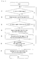
- step 1 is performed to cause the CPU 50 to send a port-specifying signal to the input port 46 through a transmission line 56 and check to see if there is a signal of detection of a drip (i.e., an electrical signal output from the microphone 34) in the input port 46. If there is one, it is input to the CPU 50. If not, program execution goes back to START.
- step 2 the CPU 50 sends a port signal to the input port 46, and reads the time input to the input port 46 from the clock 40.
- step 3 it is determined whether there are a total of two or more time readings, including that taken immediately before this, in the CPU 50.
- step 4 the CPU 50 subtracts the preceding time (i.e., the time read in step 2 during the preceding execution of the program) from the current time read in step 2 (i.e., the most recent time reading) to determine the interval of time at which the intravenous fluid has dripped from the tube 14 into the drip-feed bottle 18. Also in step 4, based on data stored in the RAM 52, the CPU 50 calculates the actual rate at which the intravenous fluid drips from the tube 14 into the drip-feed bottle 18. In step 5, from the actual rate obtained in step 4 and a predetermined rate stored in the computer 44 in advance, a correction value is calculated .
- step 6 based on the correction vale obtained in step 5, the amount by which to constrict the supply pipe 20 or to release the supply pipe 20 from constriction is calculated. Also in step 6, a signal indicative of that amount is sent to the output port 48, and is output thence to the D/A converter 60 and converted into an analog signal thereby. The analog signal is output to the stepping motor of the constricting device 36.
- the amount of an intravenous fluid to be administered to a patient may be programmed in advance. If such an amount has been programmed in advance, the program of Fig. 3 has the following additional steps. Between steps 2 and 3 the total amount of the intravenous fluid that has dripped into the bottle 18 is calculated, and after step 6 that total amount is compared with the programmed amount. Then, if the actual total amount is smaller than the programmed amount, execution goes back to step 1. When the programmed amount is reached, a signal is output to the constricting device 36 to cause the constricting device 36 to constrict the supply pipe 20 such that the flow of intravenous fluid is stopped. Thereupon the program is completed.
- the period of time for which an intravenous fluid is to De administered to a patient may be programmed in advance. If such a period of time has been programmed in advance, the program of Fig. 3 has the following additional steps. Measurement of time that elapses is started when the first signal of detection of a drip is detected by the CPU 50 (in step 2). After step 6, the time that has actually elapsed is compared with the programmed time. Then, if the actual time that has elapsed is shorter than the programmed period of time, execution goes back to step 1. When the programmed period of time is reached, a signal is output to the constricting device 36 to cause the constricting device 36 to constrict the supply pipe 20 such that the flow of intravenous fluid is stopped. Thereupon the program is completed.
- Fig. 4 shows a program for causing an intravenous fluid to drip at predetermined regular intervals of time.
- step 1 is performed to determine whether there is a "release signal", or a signal to rotate the stepping motor of the constricting device 36 such that the supply pipe 20 is released from constriction. If not, execution goes back to START. If there is one, step 2 is performed to rotate the stepping motor for a predetermined angle such that the supply pipe 20 is released from constriction.
- step 3 the CPU 50 checks to see if there is a signal of detection of a drip (of the intravenous fluid) in the input port 46. If not, execution goes back to step 2. If there is one, it is input to the CPU 50.
- step 4 the stepping motor is so rotated as to constrict the supply pipe 20 such that the flow of intravenous fluid is stopped (by the constricting device 36).
- step 5 the total amount of intravenous fluid that has dripped from the tube 14 into the bottle 18 is calculated.
- step 6 it is determined whether a programmed total amount of intravenous fluid has been reached. If not, execution goes back to START. If yes, step 7 is performed to stop the fluid from dripping into the bottle 18 and give an alarm. Thereupon the program is completed.
- a drip-detecting device of Fig. 6 may be used for the construction of Fig. 1.
- the drip-detecting device of Fig. 6 includes a pair of opposed clipping elements 22a and 22b located with the supply pipe 20 between. The two clipping elements are biased toward each other by means of a spring (not shown).
- An air bag 24 is connected to the inside of one clipping element 22a, while a cushioning element 28 is connected to the inside of the other clipping element 22b. Both the air bag 24 and the cushioning element 28 are of elastic material.
- a microphone 34 is located in an opening of the clipping element 22a and is connected to the outside of the air bag 24. Since the two clipping elements are biased toward each other, the air bag 24 attaches very closely to the supply pipe 20.
Landscapes
- Health & Medical Sciences (AREA)
- Engineering & Computer Science (AREA)
- Heart & Thoracic Surgery (AREA)
- Hematology (AREA)
- Veterinary Medicine (AREA)
- Vascular Medicine (AREA)
- Anesthesiology (AREA)
- Biomedical Technology (AREA)
- Public Health (AREA)
- General Health & Medical Sciences (AREA)
- Life Sciences & Earth Sciences (AREA)
- Animal Behavior & Ethology (AREA)
- Automation & Control Theory (AREA)
- Physics & Mathematics (AREA)
- General Physics & Mathematics (AREA)
- Infusion, Injection, And Reservoir Apparatuses (AREA)
Claims (10)
- Appareil pour contrôler la vitesse d'égouttement d'un fluide intraveineux comprenant :- des moyens de détection de gouttes pour détecter qu'un fluide intraveineux s'égoutte dans une bouteille d'alimentation en gouttes (18),- une horloge (40) pour mesurer le temps et indiquer le temps disponibles- des moyens de constriction (36) connectés à un tuyau d'alimentation en fluide (20) s'étendant à partir de la bouteille (18) dans une direction aval, pour resserrer le tuyau d'alimentation (20) et,- un contrôleur d'écoulement (38) pour contrôler l'amplitude de constriction du tuyau d'alimentation (20) par les moyens de constriction (36), basée sur un signal de détection d'une goutte à partir des moyens de détection de gouttes et d'un signal de temps issu de l'horloge (40),caractérisé en ce que les moyens de détection de gouttes sont adaptés à détecter une variation de pression créée par chacune des gouttes de fluide intraveineux s'égouttant dans la bouteille (18).
- Appareil selon la revendication 1, caractérisé en ce que les moyens de détection de gouttes comprennent un microphone (34) qui détecte des ondes sonores produites par le fluide intraveineux s'égouttant dans la bouteille (18).
- Appareil selon la revendication 1, caractérisé en ce que les moyens de détection de gouttes comprennent des moyens pour détecter des vibrations créées par le fluide intraveineux s'égouttant dans la bouteille (18).
- Appareil selon l'une quelconque des revendications 1 à 3, caractérisé en ce que les moyens de détection de gouttes comprennent :- une paire d'élément de serrage (22a, 22b) entre lesquels le tuyau d'alimentation (20) est situé et qui sont sollicités l'un vers l'autre au moyen d'un ressort, et- une poche d'air (24) connectée à l'intérieur d'un des éléments de serrage et pressée contre le tuyau d'alimentation (20),dans lequel les moyens pour détecter la variation de pression créée par le fluide intraveineux s'égouttant dans la bouteille (18) sont connectés à la poche d'air (24).
- Appareil selon l'une quelconque des revendications 1 à 4, caractérisé en ce que le contrôleur d'écoulement (38) comprend :- des moyens pour déterminer l'intervalle de temps auquel le fluide intraveineux s'égoutte dans la bouteille (18) basés sur des signaux de détection de gouttes issus des moyens de détection de gouttes,- des moyens pour calculer la vitesse effective d'égouttement du fluide intraveineux dans la bouteille 18, basés sur ledit intervalle de temps, et pour comparer ladite vitesse effective et une vitesse d'égouttement programmée et calculer une valeur de correction par laquelle ledit intervalle de temps est ajusté,- des moyens pour calculer l'amplitude avec laquelle le tuyau d'alimentation (20) doit être resserré, basés sur ladite valeur de correction, et pour produire auxdits moyens de constriction (36) un signal pour resserrer le tuyau d'alimentation (20) de ladite amplitude.
- Appareil selon la revendication 5, caractérisé en ce que le contrôleur d'écoulement (38) comprend en outre :- des moyens pour calculer la quantité totale de fluide intraveineux qui s'est égoutté dans la bouteille (18), basés sur des signaux de détection de gouttes issus des moyens de détection de gouttes,- des moyens pour produire aux moyens de constriction (36) un signal d'arrêt pour amener des moyens de constriction (36) à resserrer le tuyau d'alimentation (20) de telle sorte que le fluide intraveineux s'arrête de s'égoutter, lorsqu'une quantité totale programmée de fluide intraveineux à administrer à un patient a été atteinte.
- Appareil selon la revendication 6, caractérisé en ce que le contrôleur d'écoulement (38) comprend en outre des moyens pour donner une alarme après que ledit signal d'arrêt a été produit.
- Appareil selon la revendication 5, caractérisé en ce que le contrôleur d'écoulement (38) comprend en outre :- des moyens pour calculer la période totale de temps pendant laquelle le fluide intraveineux s'est égoutté, basés sur les signaux de détection de gouttes issus des moyens de détection gouttes, et- des moyens pour produire aux moyens de constriction (36) un signal d'arrêt pour amener les moyens de constriction (36) à resserrer le tuyaux d'alimentation (20) de telle sorte que fluide intraveineux s'arrête de s'égoutter, lorsqu'une période de temps totale programmée a été atteinte.
- Appareil selon la revendication 8, caractérisé en ce que le contrôleur d'écoulement (38) comprend en outre des moyens pour donner une alarme après que ledit signal d'arrêt a été produit.
- Appareil selon l'une quelconque des revendications 1 à 9, caractérisé en ce que le contrôleur d'écoulement (38) comprend :- des moyens pour fournir aux moyens de constriction (36) un signal pour faire tourner un moteur pas à pas des moyens de constriction (36) sur un angle prédéterminé de telle sorte que le tuyau d'alimentation (20) est libéré de la constriction par une quantité prédéterminée, et- des moyens pour fournir aux moyens de constriction (36) un signal pour faire tourner le moteur pas à pas des moyens de constriction (36) de telle sorte que le tuyau d'alimentation (20) est resserré, basés sur des signaux de détection de gouttes issus des moyens de détection de gouttes.
Applications Claiming Priority (4)
| Application Number | Priority Date | Filing Date | Title |
|---|---|---|---|
| JP3237016A JPH07144020A (ja) | 1991-08-23 | 1991-08-23 | 輸液の点滴量調節装置 |
| JP237016/91 | 1991-08-23 | ||
| JP3246916A JPH0749053B2 (ja) | 1991-08-30 | 1991-08-30 | 輸液滴下検出装置 |
| JP246916/91 | 1991-08-30 |
Publications (3)
| Publication Number | Publication Date |
|---|---|
| EP0529569A2 EP0529569A2 (fr) | 1993-03-03 |
| EP0529569A3 EP0529569A3 (en) | 1993-11-24 |
| EP0529569B1 true EP0529569B1 (fr) | 1996-07-24 |
Family
ID=26533003
Family Applications (1)
| Application Number | Title | Priority Date | Filing Date |
|---|---|---|---|
| EP92114416A Expired - Lifetime EP0529569B1 (fr) | 1991-08-23 | 1992-08-24 | Appareil pour controller le débit de goutte d'un fluide intraveineux |
Country Status (4)
| Country | Link |
|---|---|
| US (1) | US5254102A (fr) |
| EP (1) | EP0529569B1 (fr) |
| KR (1) | KR930003929A (fr) |
| DE (1) | DE69212405T2 (fr) |
Families Citing this family (39)
| Publication number | Priority date | Publication date | Assignee | Title |
|---|---|---|---|---|
| KR100403695B1 (ko) * | 2000-11-09 | 2003-11-01 | 가부시끼가이샤메디코스히라타 | 자동제어식 포터블 점적장치 |
| KR100786667B1 (ko) * | 2001-05-04 | 2007-12-21 | 오리온피디피주식회사 | 부쓰트래핑 레벨 쉬프터 방식의 플라즈마 디스플레이 패널 구동회로의 고전압 출력단 회로 |
| US8626257B2 (en) | 2003-08-01 | 2014-01-07 | Dexcom, Inc. | Analyte sensor |
| US7591801B2 (en) | 2004-02-26 | 2009-09-22 | Dexcom, Inc. | Integrated delivery device for continuous glucose sensor |
| US20190357827A1 (en) | 2003-08-01 | 2019-11-28 | Dexcom, Inc. | Analyte sensor |
| US8886273B2 (en) | 2003-08-01 | 2014-11-11 | Dexcom, Inc. | Analyte sensor |
| US7920906B2 (en) | 2005-03-10 | 2011-04-05 | Dexcom, Inc. | System and methods for processing analyte sensor data for sensor calibration |
| US9247900B2 (en) | 2004-07-13 | 2016-02-02 | Dexcom, Inc. | Analyte sensor |
| US8425416B2 (en) | 2006-10-04 | 2013-04-23 | Dexcom, Inc. | Analyte sensor |
| US8287453B2 (en) | 2003-12-05 | 2012-10-16 | Dexcom, Inc. | Analyte sensor |
| US8532730B2 (en) | 2006-10-04 | 2013-09-10 | Dexcom, Inc. | Analyte sensor |
| US8425417B2 (en) | 2003-12-05 | 2013-04-23 | Dexcom, Inc. | Integrated device for continuous in vivo analyte detection and simultaneous control of an infusion device |
| US8364231B2 (en) | 2006-10-04 | 2013-01-29 | Dexcom, Inc. | Analyte sensor |
| US11633133B2 (en) | 2003-12-05 | 2023-04-25 | Dexcom, Inc. | Dual electrode system for a continuous analyte sensor |
| US8423114B2 (en) | 2006-10-04 | 2013-04-16 | Dexcom, Inc. | Dual electrode system for a continuous analyte sensor |
| US8364230B2 (en) | 2006-10-04 | 2013-01-29 | Dexcom, Inc. | Analyte sensor |
| US8808228B2 (en) | 2004-02-26 | 2014-08-19 | Dexcom, Inc. | Integrated medicament delivery device for use with continuous analyte sensor |
| US8886272B2 (en) | 2004-07-13 | 2014-11-11 | Dexcom, Inc. | Analyte sensor |
| US8989833B2 (en) | 2004-07-13 | 2015-03-24 | Dexcom, Inc. | Transcutaneous analyte sensor |
| US7783333B2 (en) | 2004-07-13 | 2010-08-24 | Dexcom, Inc. | Transcutaneous medical device with variable stiffness |
| DE602005018518D1 (de) | 2004-10-21 | 2010-02-04 | Novo Nordisk As | Injektionsvorrichtung mit einem prozessor zur sammlung von ausstossinformationen |
| BRPI0708856A2 (pt) * | 2006-03-20 | 2011-06-14 | Novo Nordisk As | màdulo eletrânico para dispositivos mecÂnicos de dispensa de medicaÇço |
| US8298142B2 (en) | 2006-10-04 | 2012-10-30 | Dexcom, Inc. | Analyte sensor |
| US8562528B2 (en) | 2006-10-04 | 2013-10-22 | Dexcom, Inc. | Analyte sensor |
| US8275438B2 (en) | 2006-10-04 | 2012-09-25 | Dexcom, Inc. | Analyte sensor |
| US8447376B2 (en) | 2006-10-04 | 2013-05-21 | Dexcom, Inc. | Analyte sensor |
| US8478377B2 (en) | 2006-10-04 | 2013-07-02 | Dexcom, Inc. | Analyte sensor |
| US8449464B2 (en) | 2006-10-04 | 2013-05-28 | Dexcom, Inc. | Analyte sensor |
| CA2688184A1 (fr) | 2007-06-08 | 2008-12-18 | Dexcom, Inc. | Dispositif de distribution de medicament integre pour une utilisation avec un capteur de substance a analyser en continu |
| EP4159114B1 (fr) | 2007-10-09 | 2024-04-10 | DexCom, Inc. | Système d'administration d'insuline intégré avec un capteur de glucose en continu |
| US8396528B2 (en) | 2008-03-25 | 2013-03-12 | Dexcom, Inc. | Analyte sensor |
| US9149220B2 (en) | 2011-04-15 | 2015-10-06 | Dexcom, Inc. | Advanced analyte sensor calibration and error detection |
| US8531517B2 (en) * | 2010-07-15 | 2013-09-10 | Kai Tao | IV monitoring by video and image processing |
| KR101058539B1 (ko) * | 2011-02-23 | 2011-08-23 | 이두용 | 수액유량 조절기, 수액유량 조절세트 및 수액유량 조절방법 |
| CN105163777A (zh) | 2013-02-25 | 2015-12-16 | 希福特实验室有限公司 | 用于监控通过滴注器的流体的传送的装置、方法和系统 |
| US11464905B2 (en) | 2013-02-25 | 2022-10-11 | Shift Labs, Inc. | Monitoring device including an emitter emitting electromagnetic radiation and a detector positioned to receive the radiation to determine one or more rolling average flow rates |
| WO2017132941A1 (fr) * | 2016-02-04 | 2017-08-10 | 金宙科技有限公司 | Dispositif de mesure de débit de liquide |
| US11331022B2 (en) | 2017-10-24 | 2022-05-17 | Dexcom, Inc. | Pre-connected analyte sensors |
| DK3928687T3 (da) | 2017-10-24 | 2024-09-30 | Dexcom Inc | Bærbar indretning med på forhånd forbundet analytsensor |
Family Cites Families (18)
| Publication number | Priority date | Publication date | Assignee | Title |
|---|---|---|---|---|
| US2807012A (en) * | 1953-06-08 | 1957-09-17 | Schwarz Herbert | Transfusion monitoring device |
| US4261388A (en) * | 1978-05-19 | 1981-04-14 | Frenshore Ltd. | Drop rate controller |
| GB2021290B (en) * | 1978-05-19 | 1982-10-27 | Frenshore Ltd | Automatic flow control |
| EP0018817A1 (fr) * | 1979-04-30 | 1980-11-12 | Peter Gilbert Lale | Méthode et appareillage pour mesurer une vitesse d'égouttement |
| US4460353A (en) * | 1980-09-08 | 1984-07-17 | Imed Corporation | Drop controller |
| JPS57211361A (en) * | 1981-06-23 | 1982-12-25 | Terumo Corp | Liquid injecting apparatus |
| JPS5836562A (ja) * | 1981-08-28 | 1983-03-03 | テルモ株式会社 | 点滴量制御装置 |
| US4507112A (en) * | 1982-04-05 | 1985-03-26 | Ipco Corporation | Infusion monitor |
| US4496351A (en) * | 1982-04-05 | 1985-01-29 | Ipco Corporation | Infusion monitor |
| US4645489A (en) * | 1982-11-30 | 1987-02-24 | Beta Phase, Inc. | Fluid delivery apparatus with shape-memory flow control element |
| US4493710A (en) * | 1983-11-14 | 1985-01-15 | Ivy Medical, Inc. | Intravenous drip rate control device |
| DE3404144A1 (de) * | 1984-02-07 | 1985-08-08 | "gutta" Gesellschaft für Infusionstechnik mbH, 2000 Hamburg | Monolithisches miniaturisiertes schwerkraftinfusionsregelgeraet |
| US4634426A (en) * | 1984-12-11 | 1987-01-06 | Baxter Travenol Laboratories | Medical infusion controller and user interface |
| US4718896A (en) * | 1986-01-10 | 1988-01-12 | Abbott Laboratories | Apparatus and method for controlling the flow of fluid through an administration set |
| NL8802307A (nl) * | 1987-12-17 | 1989-07-17 | Mr W M H Kerbosch B V Handelen | Inrichting voor het regelen van de stroomsnelheid van een infusievloeistof bij een infusiesysteem. |
| US4946439A (en) * | 1988-08-15 | 1990-08-07 | Critikon, Inc. | Dual source parenteral infusion system with secondary infusion module |
| JPH02120628A (ja) * | 1988-10-31 | 1990-05-08 | Mitsubishi Electric Corp | 滴下監視装置 |
| JPH03231680A (ja) * | 1990-02-06 | 1991-10-15 | Terumo Corp | 点滴検出機及びそれを備えた点滴警報装置並びに点滴量制御装置 |
-
1992
- 1992-08-22 KR KR1019920015093A patent/KR930003929A/ko not_active Ceased
- 1992-08-24 US US07/933,811 patent/US5254102A/en not_active Expired - Fee Related
- 1992-08-24 EP EP92114416A patent/EP0529569B1/fr not_active Expired - Lifetime
- 1992-08-24 DE DE69212405T patent/DE69212405T2/de not_active Expired - Fee Related
Also Published As
| Publication number | Publication date |
|---|---|
| US5254102A (en) | 1993-10-19 |
| EP0529569A3 (en) | 1993-11-24 |
| DE69212405D1 (de) | 1996-08-29 |
| KR930003929A (ko) | 1993-03-22 |
| DE69212405T2 (de) | 1997-01-02 |
| EP0529569A2 (fr) | 1993-03-03 |
Similar Documents
| Publication | Publication Date | Title |
|---|---|---|
| EP0529569B1 (fr) | Appareil pour controller le débit de goutte d'un fluide intraveineux | |
| US6952963B2 (en) | Method for detecting a liquid level in a container in a circuit and a dialysis machine for actuating the method | |
| JP3321620B2 (ja) | 液体送り出しシステム中の空気の検知のための装置及び方法 | |
| US4221004A (en) | Adjustable ultrasonic level measurement device | |
| US5256155A (en) | Drop detection method and apparatus | |
| US5002539A (en) | IV rate meter | |
| US4174637A (en) | Pressure monitoring system | |
| EP1182452B1 (fr) | Méthode pour la détection des bulles d'air | |
| US4703314A (en) | Empty container detector with drop sensor | |
| US4509943A (en) | Infusion control apparatus | |
| US8631683B2 (en) | Dialysis systems including non-invasive multi-function sensor systems | |
| US5060654A (en) | Identification method for the cuff type of a sphygmomanometer | |
| CN101189509A (zh) | 借助超声波监视液体流是否存在空气的方法和装置 | |
| JPH11287817A (ja) | 速度測定装置及び速度測定方法 | |
| EP0981201B1 (fr) | Détecteur de passages par zéro puis procédé de détermination d'une valeur de passage par zéro | |
| DE69223662D1 (de) | Elektronischer Blutdruckmesser | |
| JP2007530933A (ja) | 可変的閾値を有する超音波信号のゼロ交差検出 | |
| EP1231456B1 (fr) | Dispositif et méthode pour déterminer, par voie acoustique, la température d'un fluide | |
| US5704923A (en) | Liquid level detector and alarm device for drip infusion sets | |
| JP2005084017A (ja) | 気泡量の検出システムおよび該気泡量の検出システムを搭載した医療用装置 | |
| JPH07144020A (ja) | 輸液の点滴量調節装置 | |
| US4929825A (en) | Means for detecting damage to the card connecting the photosensor and main body pulsimeter | |
| GB2031158A (en) | Flow measurement | |
| CN221867055U (zh) | 一种全自动脑脊液引流控制仪 | |
| JPH0898885A (ja) | 電子式点滴管理用点滴瓶 |
Legal Events
| Date | Code | Title | Description |
|---|---|---|---|
| PUAI | Public reference made under article 153(3) epc to a published international application that has entered the european phase |
Free format text: ORIGINAL CODE: 0009012 |
|
| AK | Designated contracting states |
Kind code of ref document: A2 Designated state(s): DE FR GB IT SE |
|
| 17P | Request for examination filed |
Effective date: 19930605 |
|
| PUAL | Search report despatched |
Free format text: ORIGINAL CODE: 0009013 |
|
| AK | Designated contracting states |
Kind code of ref document: A3 Designated state(s): DE FR GB IT SE |
|
| 17Q | First examination report despatched |
Effective date: 19941202 |
|
| GRAH | Despatch of communication of intention to grant a patent |
Free format text: ORIGINAL CODE: EPIDOS IGRA |
|
| GRAH | Despatch of communication of intention to grant a patent |
Free format text: ORIGINAL CODE: EPIDOS IGRA |
|
| GRAA | (expected) grant |
Free format text: ORIGINAL CODE: 0009210 |
|
| AK | Designated contracting states |
Kind code of ref document: B1 Designated state(s): DE FR GB IT SE |
|
| PG25 | Lapsed in a contracting state [announced via postgrant information from national office to epo] |
Ref country code: IT Free format text: LAPSE BECAUSE OF FAILURE TO SUBMIT A TRANSLATION OF THE DESCRIPTION OR TO PAY THE FEE WITHIN THE PRE;WARNING: LAPSES OF ITALIAN PATENTS WITH EFFECTIVE DATE BEFORE 2007 MAY HAVE OCCURRED AT ANY TIME BEFORE 2007. THE CORRECT EFFECTIVE DATE MAY BE DIFFERENT FROM THE ONE RECORDED.SCRIBED TIME-LIMIT Effective date: 19960724 |
|
| REF | Corresponds to: |
Ref document number: 69212405 Country of ref document: DE Date of ref document: 19960829 |
|
| PG25 | Lapsed in a contracting state [announced via postgrant information from national office to epo] |
Ref country code: SE Effective date: 19961024 |
|
| ET | Fr: translation filed | ||
| PLBE | No opposition filed within time limit |
Free format text: ORIGINAL CODE: 0009261 |
|
| 26N | No opposition filed | ||
| PGFP | Annual fee paid to national office [announced via postgrant information from national office to epo] |
Ref country code: GB Payment date: 19970813 Year of fee payment: 6 |
|
| PGFP | Annual fee paid to national office [announced via postgrant information from national office to epo] |
Ref country code: FR Payment date: 19970827 Year of fee payment: 6 |
|
| PGFP | Annual fee paid to national office [announced via postgrant information from national office to epo] |
Ref country code: DE Payment date: 19971031 Year of fee payment: 6 |
|
| PG25 | Lapsed in a contracting state [announced via postgrant information from national office to epo] |
Ref country code: GB Free format text: LAPSE BECAUSE OF NON-PAYMENT OF DUE FEES Effective date: 19980824 |
|
| GBPC | Gb: european patent ceased through non-payment of renewal fee |
Effective date: 19980824 |
|
| PG25 | Lapsed in a contracting state [announced via postgrant information from national office to epo] |
Ref country code: FR Free format text: LAPSE BECAUSE OF NON-PAYMENT OF DUE FEES Effective date: 19990430 |
|
| PG25 | Lapsed in a contracting state [announced via postgrant information from national office to epo] |
Ref country code: DE Free format text: LAPSE BECAUSE OF NON-PAYMENT OF DUE FEES Effective date: 19990601 |
|
| REG | Reference to a national code |
Ref country code: FR Ref legal event code: ST |