EP0530008A2 - Appareil de lubrification automatique pour machine à couper - Google Patents
Appareil de lubrification automatique pour machine à couper Download PDFInfo
- Publication number
- EP0530008A2 EP0530008A2 EP92307766A EP92307766A EP0530008A2 EP 0530008 A2 EP0530008 A2 EP 0530008A2 EP 92307766 A EP92307766 A EP 92307766A EP 92307766 A EP92307766 A EP 92307766A EP 0530008 A2 EP0530008 A2 EP 0530008A2
- Authority
- EP
- European Patent Office
- Prior art keywords
- cutting
- cutting head
- lubricating
- cylinder
- lubricating device
- Prior art date
- Legal status (The legal status is an assumption and is not a legal conclusion. Google has not performed a legal analysis and makes no representation as to the accuracy of the status listed.)
- Granted
Links
Images


Classifications
-
- B—PERFORMING OPERATIONS; TRANSPORTING
- B26—HAND CUTTING TOOLS; CUTTING; SEVERING
- B26D—CUTTING; DETAILS COMMON TO MACHINES FOR PERFORATING, PUNCHING, CUTTING-OUT, STAMPING-OUT OR SEVERING
- B26D7/00—Details of apparatus for cutting, cutting-out, stamping-out, punching, perforating, or severing by means other than cutting
- B26D7/08—Means for treating work or cutting member to facilitate cutting
- B26D7/088—Means for treating work or cutting member to facilitate cutting by cleaning or lubricating
-
- D—TEXTILES; PAPER
- D06—TREATMENT OF TEXTILES OR THE LIKE; LAUNDERING; FLEXIBLE MATERIALS NOT OTHERWISE PROVIDED FOR
- D06H—MARKING, INSPECTING, SEAMING OR SEVERING TEXTILE MATERIALS
- D06H7/00—Apparatus or processes for cutting, or otherwise severing, specially adapted for the cutting, or otherwise severing, of textile materials
-
- Y—GENERAL TAGGING OF NEW TECHNOLOGICAL DEVELOPMENTS; GENERAL TAGGING OF CROSS-SECTIONAL TECHNOLOGIES SPANNING OVER SEVERAL SECTIONS OF THE IPC; TECHNICAL SUBJECTS COVERED BY FORMER USPC CROSS-REFERENCE ART COLLECTIONS [XRACs] AND DIGESTS
- Y10—TECHNICAL SUBJECTS COVERED BY FORMER USPC
- Y10T—TECHNICAL SUBJECTS COVERED BY FORMER US CLASSIFICATION
- Y10T83/00—Cutting
- Y10T83/263—With means to apply transient nonpropellant fluent material to tool or work
Definitions
- This invention relates to an automatic lubricating device for a cutting head of a cutting machine which is used for cutting a pile of soft sheets such as cloth.
- This invention has been achieved to fully solve the problem and its object is to provide an automatic lubricating device for a cutting head of a cutting machine which enables automatic lubrication to the drive mechanism of a cutting blade without lowering efficiency in operation.
- the cutting head comprises an oil sump provided inside the cutting head and below the cutting blade drive mechanism, a lubrication cylinder is operated coincident with an operation of the cylinder for an up and down movement, a pump is driven by the lubricating cylinder, and a nozzle through which lubricating oil in the oil sump is jetted out by a pressure of the pump to the cutting blade drive mechanism.
- the lubricating oil is jetted out by a pressure of the pump to the cutting blade drive mechanism either when the cutting head is lifted up and when the cutting head is moved downwardly.
- the used lubricating oil drops down in the oil sump thereby oil lubricating to the cutting blade drive mechanism is conducted automatically when a cutting operation occurs.
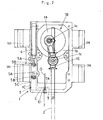
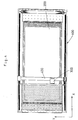
- FIG. 2 shows a front cross-sectional view of a cutting head 1 and Figure 3 shows a left side sectional view of the cutting head 1.
- a cutting blade 2 is reciprocated by a motor 1A through a cutting blade drive mechanism 1B.
- the cutting blade drive mechanism 1B is set within a case 1C and an eccentric disc 1a, which is attached to an end of a drive axis 1D, and a blade attaching bar 1E are connected by a connecting rod 1b of which two ends are connected to the eccentric disc 1a and the blade attaching bar 1E respectively by pins 1c, 1c.
- an oil sump 3 is provided inside the case 1C.
- a guide block 1F is attached in front of the case 1C.
- Guide holes 1G, 1G are perforated in the upper part and the lower part of the guide block 1F respectively and the blade attaching bar 1E extends through the upper and the lower guide holes 1G, 1G.
- the cutting blade 2 is removably attached to the blade attaching bar 1E and extends vertically from the cutting head 1.
- Guiding bar passages 1H are provided in left and right sides of the case 1C for operation of the connecting rod 1b.
- a hollow space 5C is formed and a lubricating cylinder 4 is provided in the upper part inside the hollow space 5C.
- a piston 5B is attached to a piston rod 5A of the lubricating cylinder 4 and thereby a lubricant pump 5 is formed.
- a narrow path 6 is formed between the bottom portion of the hollow space 5C and oil sump 3.
- One end of the narrow path 6 has an opening at the hollow space 5C and a nozzle attaching performation 61 is formed at the other end opening to the oil sump 3.
- a nozzle 7 is attached to the nozzle attaching perforation 61 and an opening jet 7A of the nozzle 7 is open to the oil sump 3.
- a supporting body 8 is projected from a reciprocating carriage 300 which is referring to in the following paragraphs, and provided with a pair of guiding bars 8A, which are extend through the guiding bar passages 1H.
- a base plate 8B is provided and a double acting pneumatic cylinder 9 for lifting up and down is provided on the base plate 8B. According to the in and out action of a piston rod of the cylinder 9, the cutting head 1 is lifted up and down.
- a two-dot chain of thick lines in Figure 1 show a schematic of a high-pressure air circuit.
- High-pressure air is supplied from a high-pressure air source 10 to the cylinder 9 through an air pipe path 11, while high-pressure air is also supplied to the lubricating cylinder 4 through an air pipe path 11A which is branched off from the air pipe path 11.
- the lubricating cylinder 4 is also supplied with the high-pressure air.
- the cylinder 9 for lifting up and down and the lubricating cylinder 4 are controlled by a control center (not shown in the figures).
- Figure 4 shows a plane view of a cutting bed 100.
- the cutting head 1 is placed above a bed body 200 and supported by a carriage 300 and a carriage 400.
- the carriage 400 is set to slide in a x-direction above the bed body 200 and the carriage 300 attached to the carriage 400 is set to slide in a Y-direction. Both the carriage 400 and the carriage 300 are actuated by drive control motors (not shown in the drawings) respectively controlled by a control center (not shown in the drawings).
- the cutting head 1 is positioned in the upper position when it is not in use. When a cutting operation starts, the cutting head 1 is moved to an operating position from the non-use position by the carriages 300 and 400.
- the cutting head 1 is lowered by operation of the motor 1A so that the blade 2 penetrates through the pile of sheets.
- the lubricating oil O jets out from the nozzle 7 toward the drive mechanism 1B. This means that lubrication occurs before the cutting operation starts.
- the cutting head 1 is lifted up so that the cutting blade 2 is spaced from the pile of sheets, and the cutting head 1 is moved back to the non-use position by the carriages 300 and 400.
- a lubricating device proposed in the present invention may be formed so that lubrication occurs after a cutting operation. That is, the lubricating oil O jets out from the nozzle 7 toward the drive mechanism 1B by actuating the pump 5 by supplying high-pressure air to the lubricating cylinder 4, while the cutting head 1 is lifted up by supplying the high-pressure air to the double acting pneumatic cylinder 9 from the high-pressure air source 10. In this case, lubrication occurs when the cutting head is lifted up and the cutting blade 2 is spaced from the pile of sheets.
- a lubricating device may be formed so that lubricating occurs both before and after a cutting operation. That is, when high-pressure air is supplied from the high-pressure air source 10 to the cylinder 9 for lifting up and down and the cutting head 1 is lifted up or down, the lubricating oil O jets out from the nozzle 7 toward the drive mechanism 1B by actuating the pump 5 by supplying high-pressure air to the lubricating cylinder 4. In this case, lubrication occurs both before and after a cutting operation, that is, both when the cutting head is moved downwardly and when the cutting head is lifted up.
Landscapes
- Engineering & Computer Science (AREA)
- Life Sciences & Earth Sciences (AREA)
- Forests & Forestry (AREA)
- Mechanical Engineering (AREA)
- Textile Engineering (AREA)
- Drilling And Boring (AREA)
- Control Of Cutting Processes (AREA)
- Treatment Of Fiber Materials (AREA)
- Nonmetal Cutting Devices (AREA)
- Coiling Of Filamentary Materials In General (AREA)
Applications Claiming Priority (2)
| Application Number | Priority Date | Filing Date | Title |
|---|---|---|---|
| JP3217250A JPH0749191B2 (ja) | 1991-08-28 | 1991-08-28 | 裁断ヘッドへの自動給油装置 |
| JP217250/91 | 1991-08-28 |
Publications (3)
| Publication Number | Publication Date |
|---|---|
| EP0530008A2 true EP0530008A2 (fr) | 1993-03-03 |
| EP0530008A3 EP0530008A3 (en) | 1993-06-09 |
| EP0530008B1 EP0530008B1 (fr) | 1996-10-16 |
Family
ID=16701206
Family Applications (1)
| Application Number | Title | Priority Date | Filing Date |
|---|---|---|---|
| EP92307766A Expired - Lifetime EP0530008B1 (fr) | 1991-08-28 | 1992-08-26 | Appareil de lubrification automatique pour machine à couper |
Country Status (6)
| Country | Link |
|---|---|
| US (1) | US5246088A (fr) |
| EP (1) | EP0530008B1 (fr) |
| JP (1) | JPH0749191B2 (fr) |
| KR (1) | KR100209529B1 (fr) |
| DE (1) | DE69214579T2 (fr) |
| ES (1) | ES2093209T3 (fr) |
Cited By (5)
| Publication number | Priority date | Publication date | Assignee | Title |
|---|---|---|---|---|
| US7757372B2 (en) | 2003-09-18 | 2010-07-20 | Trumpf Werkzeugmaschinen Gmbh + Co. Kg | Sheet metal processing methods utilizing a combined punching and forming machine |
| CN104499263A (zh) * | 2014-12-15 | 2015-04-08 | 拓卡奔马机电科技有限公司 | 裁床的真空自动调节装置 |
| CN106272608A (zh) * | 2016-08-25 | 2017-01-04 | 岳西县金瑞机械有限公司 | 一种多功能茯苓切片机横向切割装置 |
| CN106400449A (zh) * | 2016-06-23 | 2017-02-15 | 广东溢达纺织有限公司 | 自动切筒条设备 |
| CN110863338A (zh) * | 2019-12-17 | 2020-03-06 | 景红锋 | 一种基于润油引流压布减振的高速断布装置 |
Families Citing this family (9)
| Publication number | Priority date | Publication date | Assignee | Title |
|---|---|---|---|---|
| US5509206A (en) * | 1993-10-27 | 1996-04-23 | Rowe; Jack L. | Portable or table mounted band saw utilizing dual cutting procedure of band saw blade |
| US5444634A (en) * | 1994-04-28 | 1995-08-22 | Illinois Tool Works Inc. | Lubricant nozzle positioning system and method |
| CA2687619C (fr) * | 2009-12-08 | 2011-11-15 | Norwood Industries Inc. | Controleur integre de lubrification de lames |
| CN105729524A (zh) * | 2016-03-31 | 2016-07-06 | 镇江市世龙食品机械有限公司 | 一种切片机构 |
| CN106335098B (zh) * | 2016-08-25 | 2019-05-17 | 岳西县金瑞机械有限公司 | 一种多功能茯苓切片机 |
| CN106738256A (zh) * | 2016-12-30 | 2017-05-31 | 苏州达力客自动化科技有限公司 | 一种自动去泥旋坯刀具 |
| CN107363880A (zh) * | 2017-08-09 | 2017-11-21 | 湖州翼腾自动化设备有限公司 | 一种具有防锈润滑功能的塑料制品切割机 |
| JP6302125B1 (ja) * | 2017-09-22 | 2018-03-28 | 株式会社松浦機械製作所 | 切削油の供給方法 |
| KR102899597B1 (ko) | 2019-12-06 | 2025-12-15 | 킴벌리-클라크 월드와이드, 인크. | 천공기 윤활 시스템 |
Family Cites Families (10)
| Publication number | Priority date | Publication date | Assignee | Title |
|---|---|---|---|---|
| US1000791A (en) * | 1910-04-09 | 1911-08-15 | John Erikson | Lubricator. |
| US2045737A (en) * | 1932-06-30 | 1936-06-30 | Cincinnati Grinders Inc | Machine tool |
| US2209938A (en) * | 1938-04-19 | 1940-07-30 | Cincinnati Bickford Tool Co | Lubricating means |
| US2425281A (en) * | 1943-09-10 | 1947-08-05 | American Tool Works Co | Lubrication of machine tools |
| US2869231A (en) * | 1957-02-25 | 1959-01-20 | Jr John B Gury | Lubricating system for cloth cutting machine |
| GB1411978A (en) * | 1972-08-31 | 1975-10-29 | Lister Co Ltd R A | Lubricating pump |
| US3830122A (en) * | 1973-03-26 | 1974-08-20 | Gerber Garment Technology Inc | Apparatus for dispensing a liquid onto a tool |
| US3960244A (en) * | 1974-09-16 | 1976-06-01 | Eastman Machine Company | Cloth cutting machine with wick lubricator |
| US4199950A (en) * | 1977-12-01 | 1980-04-29 | Hakason Alton L | Prelubricating and lubricating systems for engines |
| DE3943747C2 (de) * | 1988-02-05 | 2000-05-04 | Amada Co | Stanzwerkzeug |
-
1991
- 1991-08-28 JP JP3217250A patent/JPH0749191B2/ja not_active Expired - Fee Related
-
1992
- 1992-08-22 KR KR1019920015135A patent/KR100209529B1/ko not_active Expired - Fee Related
- 1992-08-26 EP EP92307766A patent/EP0530008B1/fr not_active Expired - Lifetime
- 1992-08-26 DE DE69214579T patent/DE69214579T2/de not_active Expired - Fee Related
- 1992-08-26 ES ES92307766T patent/ES2093209T3/es not_active Expired - Lifetime
- 1992-08-28 US US07/936,488 patent/US5246088A/en not_active Expired - Lifetime
Cited By (7)
| Publication number | Priority date | Publication date | Assignee | Title |
|---|---|---|---|---|
| US7757372B2 (en) | 2003-09-18 | 2010-07-20 | Trumpf Werkzeugmaschinen Gmbh + Co. Kg | Sheet metal processing methods utilizing a combined punching and forming machine |
| CN104499263A (zh) * | 2014-12-15 | 2015-04-08 | 拓卡奔马机电科技有限公司 | 裁床的真空自动调节装置 |
| CN106400449A (zh) * | 2016-06-23 | 2017-02-15 | 广东溢达纺织有限公司 | 自动切筒条设备 |
| CN106272608A (zh) * | 2016-08-25 | 2017-01-04 | 岳西县金瑞机械有限公司 | 一种多功能茯苓切片机横向切割装置 |
| CN106272608B (zh) * | 2016-08-25 | 2018-02-09 | 岳西县金瑞机械有限公司 | 一种多功能茯苓切片机横向切割装置 |
| CN110863338A (zh) * | 2019-12-17 | 2020-03-06 | 景红锋 | 一种基于润油引流压布减振的高速断布装置 |
| CN110863338B (zh) * | 2019-12-17 | 2022-01-07 | 东营经济技术开发区东汇新能源有限公司 | 一种基于润油引流压布减振的高速断布装置 |
Also Published As
| Publication number | Publication date |
|---|---|
| KR930004566A (ko) | 1993-03-22 |
| KR100209529B1 (ko) | 1999-07-15 |
| JPH0557671A (ja) | 1993-03-09 |
| JPH0749191B2 (ja) | 1995-05-31 |
| EP0530008A3 (en) | 1993-06-09 |
| US5246088A (en) | 1993-09-21 |
| ES2093209T3 (es) | 1996-12-16 |
| DE69214579T2 (de) | 1997-02-20 |
| EP0530008B1 (fr) | 1996-10-16 |
| DE69214579D1 (de) | 1996-11-21 |
Similar Documents
| Publication | Publication Date | Title |
|---|---|---|
| US5246088A (en) | Automatic lubricating device for a cutting head of a cutting machine | |
| EP3468754B1 (fr) | Dispositif pour la perforation des paneaux | |
| JPH05162098A (ja) | 積層物の裁断装置 | |
| IT9021510A1 (it) | Apparecchiatura per il taglio di laminati. | |
| CN110154147B (zh) | 冲孔装置 | |
| JPS5854931B2 (ja) | ブロ−チ盤 | |
| DE2318011C2 (de) | Nähvorrichtung zum Annähen von Taschen auf Kleidungsstücken | |
| KR102512428B1 (ko) | 천공 제본 장치 | |
| US5611468A (en) | Folding device for an automatic sewing machine | |
| US3945278A (en) | Apparatus for making relief cuts on previously scored glass sheets | |
| JP3159462B2 (ja) | プレス式走行パイプ切断機 | |
| EP0694347B1 (fr) | Poinçonneuse à tourelle revolver | |
| US5974990A (en) | Apparatus for the transfer of a piping strip from a preparation station on to a workpiece | |
| CN214981542U (zh) | 肩章衬布定位打孔装置 | |
| CN219385598U (zh) | 一种用于绣花机的自动剪绳装置 | |
| CN218460596U (zh) | 一种锁孔缝纫机的冲孔机构 | |
| CN110842299A (zh) | 一种料带折断机中的折料装置 | |
| CN212533034U (zh) | 一种用于服饰皮带的打孔装置 | |
| CN214419034U (zh) | 一种基于样布钻孔机的刀孔自动清理装置 | |
| CN213767913U (zh) | 一种新型打标机定位装置 | |
| CN222695793U (zh) | 盘体打孔机 | |
| KR960021423A (ko) | 카렌다용 홀더의 자동 컷팅 및 펀칭 시스템 및 제어방법 | |
| CN113043376B (zh) | 甘蔗刀手柄自动打孔机 | |
| JPH0310789A (ja) | 積層物の裁断装置 | |
| JP2576048B2 (ja) | 液圧プレス装置 |
Legal Events
| Date | Code | Title | Description |
|---|---|---|---|
| PUAI | Public reference made under article 153(3) epc to a published international application that has entered the european phase |
Free format text: ORIGINAL CODE: 0009012 |
|
| AK | Designated contracting states |
Kind code of ref document: A2 Designated state(s): DE ES FR GB IT |
|
| PUAL | Search report despatched |
Free format text: ORIGINAL CODE: 0009013 |
|
| AK | Designated contracting states |
Kind code of ref document: A3 Designated state(s): DE ES FR GB IT |
|
| 17P | Request for examination filed |
Effective date: 19930915 |
|
| 17Q | First examination report despatched |
Effective date: 19950602 |
|
| GRAG | Despatch of communication of intention to grant |
Free format text: ORIGINAL CODE: EPIDOS AGRA |
|
| GRAH | Despatch of communication of intention to grant a patent |
Free format text: ORIGINAL CODE: EPIDOS IGRA |
|
| GRAH | Despatch of communication of intention to grant a patent |
Free format text: ORIGINAL CODE: EPIDOS IGRA |
|
| GRAA | (expected) grant |
Free format text: ORIGINAL CODE: 0009210 |
|
| AK | Designated contracting states |
Kind code of ref document: B1 Designated state(s): DE ES FR GB IT |
|
| PG25 | Lapsed in a contracting state [announced via postgrant information from national office to epo] |
Ref country code: IT Free format text: LAPSE BECAUSE OF FAILURE TO SUBMIT A TRANSLATION OF THE DESCRIPTION OR TO PAY THE FEE WITHIN THE PRESCRIBED TIME-LIMIT;WARNING: LAPSES OF ITALIAN PATENTS WITH EFFECTIVE DATE BEFORE 2007 MAY HAVE OCCURRED AT ANY TIME BEFORE 2007. THE CORRECT EFFECTIVE DATE MAY BE DIFFERENT FROM THE ONE RECORDED. Effective date: 19961016 |
|
| REF | Corresponds to: |
Ref document number: 69214579 Country of ref document: DE Date of ref document: 19961121 |
|
| REG | Reference to a national code |
Ref country code: ES Ref legal event code: FG2A Ref document number: 2093209 Country of ref document: ES Kind code of ref document: T3 |
|
| ET | Fr: translation filed | ||
| PLBE | No opposition filed within time limit |
Free format text: ORIGINAL CODE: 0009261 |
|
| STAA | Information on the status of an ep patent application or granted ep patent |
Free format text: STATUS: NO OPPOSITION FILED WITHIN TIME LIMIT |
|
| 26N | No opposition filed | ||
| REG | Reference to a national code |
Ref country code: GB Ref legal event code: IF02 |
|
| PGFP | Annual fee paid to national office [announced via postgrant information from national office to epo] |
Ref country code: DE Payment date: 20070823 Year of fee payment: 16 |
|
| PGFP | Annual fee paid to national office [announced via postgrant information from national office to epo] |
Ref country code: ES Payment date: 20070926 Year of fee payment: 16 |
|
| PGFP | Annual fee paid to national office [announced via postgrant information from national office to epo] |
Ref country code: GB Payment date: 20070822 Year of fee payment: 16 |
|
| GBPC | Gb: european patent ceased through non-payment of renewal fee |
Effective date: 20080826 |
|
| PG25 | Lapsed in a contracting state [announced via postgrant information from national office to epo] |
Ref country code: DE Free format text: LAPSE BECAUSE OF NON-PAYMENT OF DUE FEES Effective date: 20090303 |
|
| REG | Reference to a national code |
Ref country code: ES Ref legal event code: FD2A Effective date: 20080827 |
|
| PGFP | Annual fee paid to national office [announced via postgrant information from national office to epo] |
Ref country code: FR Payment date: 20090814 Year of fee payment: 18 |
|
| PG25 | Lapsed in a contracting state [announced via postgrant information from national office to epo] |
Ref country code: GB Free format text: LAPSE BECAUSE OF NON-PAYMENT OF DUE FEES Effective date: 20080826 |
|
| PG25 | Lapsed in a contracting state [announced via postgrant information from national office to epo] |
Ref country code: ES Free format text: LAPSE BECAUSE OF NON-PAYMENT OF DUE FEES Effective date: 20080827 |
|
| REG | Reference to a national code |
Ref country code: FR Ref legal event code: ST Effective date: 20110502 |
|
| PG25 | Lapsed in a contracting state [announced via postgrant information from national office to epo] |
Ref country code: FR Free format text: LAPSE BECAUSE OF NON-PAYMENT OF DUE FEES Effective date: 20100831 |