EP0530041A2 - Richtwandler mit schwebenden Elektroden für akustische Oberflächenwellen - Google Patents
Richtwandler mit schwebenden Elektroden für akustische Oberflächenwellen Download PDFInfo
- Publication number
- EP0530041A2 EP0530041A2 EP92307866A EP92307866A EP0530041A2 EP 0530041 A2 EP0530041 A2 EP 0530041A2 EP 92307866 A EP92307866 A EP 92307866A EP 92307866 A EP92307866 A EP 92307866A EP 0530041 A2 EP0530041 A2 EP 0530041A2
- Authority
- EP
- European Patent Office
- Prior art keywords
- electrodes
- surface acoustic
- acoustic wave
- output side
- positive
- Prior art date
- Legal status (The legal status is an assumption and is not a legal conclusion. Google has not performed a legal analysis and makes no representation as to the accuracy of the status listed.)
- Granted
Links
- 238000010897 surface acoustic wave method Methods 0.000 title claims abstract description 69
- 238000007667 floating Methods 0.000 title claims abstract description 68
- 239000000758 substrate Substances 0.000 claims abstract description 24
- 239000000463 material Substances 0.000 claims abstract description 12
- 230000001902 propagating effect Effects 0.000 claims description 20
- 230000008878 coupling Effects 0.000 claims description 7
- 238000010168 coupling process Methods 0.000 claims description 7
- 238000005859 coupling reaction Methods 0.000 claims description 7
- 238000000034 method Methods 0.000 description 10
- 238000003780 insertion Methods 0.000 description 7
- 230000037431 insertion Effects 0.000 description 7
- 230000003247 decreasing effect Effects 0.000 description 6
- 239000010453 quartz Substances 0.000 description 3
- VYPSYNLAJGMNEJ-UHFFFAOYSA-N silicon dioxide Inorganic materials O=[Si]=O VYPSYNLAJGMNEJ-UHFFFAOYSA-N 0.000 description 3
- 238000010276 construction Methods 0.000 description 2
- 230000005684 electric field Effects 0.000 description 2
- 239000002184 metal Substances 0.000 description 2
- 230000000644 propagated effect Effects 0.000 description 2
- 229910011131 Li2B4O7 Inorganic materials 0.000 description 1
- 230000005540 biological transmission Effects 0.000 description 1
- 230000000694 effects Effects 0.000 description 1
- 238000004519 manufacturing process Methods 0.000 description 1
- 238000010295 mobile communication Methods 0.000 description 1
- 238000012986 modification Methods 0.000 description 1
- 230000004048 modification Effects 0.000 description 1
- 230000000737 periodic effect Effects 0.000 description 1
- 238000000206 photolithography Methods 0.000 description 1
- 238000010079 rubber tapping Methods 0.000 description 1
- 239000004065 semiconductor Substances 0.000 description 1
- 230000035945 sensitivity Effects 0.000 description 1
- 230000001629 suppression Effects 0.000 description 1
Images




Classifications
-
- H—ELECTRICITY
- H03—ELECTRONIC CIRCUITRY
- H03H—IMPEDANCE NETWORKS, e.g. RESONANT CIRCUITS; RESONATORS
- H03H9/00—Networks comprising electromechanical or electro-acoustic elements; Electromechanical resonators
- H03H9/02—Details
- H03H9/125—Driving means, e.g. electrodes, coils
- H03H9/145—Driving means, e.g. electrodes, coils for networks using surface acoustic waves
- H03H9/14502—Surface acoustic wave [SAW] transducers for a particular purpose
- H03H9/14505—Unidirectional SAW transducers
Definitions
- the present invention generally relates to a surface acoustic wave transducer, and more particularly to a surface acoustic wave unidirectional transducer having interdigital electrodes and floating electrodes arranged between successive interdigital electrodes.
- IDT surface acoustic wave transducer comprising a piezoelectric substrate and interdigital electrodes applied on a surface of the piezoelectric substrate.
- IDT interdigital electrodes
- IDT electrode arrangements For instance, Japanese Patent Publication Tokko Hei 3-20929, there is described a known IDT electrode arrangement, in which open-type or short-circuit-type floating electrodes are provided between successive positive and negative electrodes such that the floating electrodes are not brought into contact with the positive and negative electrodes.
- a direction of a surface acoustic wave reflected by the open-type or short-circuit-type floating electrodes becomes unidirectional.
- the unidirectional transducer such as a unidirectional transducer using a multistrip coupler, a multi-phase type unidirectional transducer and a single-phase type unidirectional transducer (refer to Japanese book, "Fundaments and Applications of Microwave Circuit", published on August 20, 1990 from Sougou Densi Shuppan, page 280).
- the known IDT electrode arrangement disclosed in the above mentioned Japanese Patent Publication belongs to the single-phase type unidirectional transducer utilizing the reflection by both the open-type and short-circuit-type floating electrodes.
- a reflecting coefficient of a metal strip electrode applied on a piezoelectric substrate varies depending upon the thickness, width, etc. of the metal electrode and a phase of a surface acoustic wave reflected by a short-circuit-type floating electrode differs from a phase of the wave reflected by the open-type floating electrode by 180 degrees.
- the open-type floating electrode is formed at a position which is deviated from a middle point between adjacent positive and negative exciting electrodes of IDT, there is produced a shift between an exciting center of the surface acoustic wave and a reflection center, so that the directionality can be attained.
- the short-circuit-type floating electrodes are used, the reflection phase is reversed, so that the reversed directionality can be obtained. Therefore, when two floating electrodes are provided, there are obtained large reflection and directionality.
- the above explained surface acoustic wave transversal filter has various properties. That is to say, since the propagating velocity of the surface acoustic wave is lower than that of the electromagnetic wave, the device can be small in size and light in weight. Further, the signal tapping on the substrate can be performed easily and the shape of the IDT electrode arrangement corresponds directly to the impulse response.
- said opposing length of electrode is made constant over the whole electrode array and an intensity of an exciting electric field is changed in the direction of the electrode array such that the electric field becomes maximum at a middle of the electrode array and is gradually decreased toward both ends of the electrode array.
- a similar function can be attained by deleting some electrodes from the electrode array.
- This later weighting method is called the electrode withdrawal weighting method.
- Fig. 1 is a plan view showing a known surface acoustic wave transducer.
- This transducer 1 comprises a substrate made of a piezoelectric material, an input or transmission side IDT electrode structure 2 and an output or reception side IDT electrode structure 3, said input and output side IDT electrode structures 2 and 3 being formed on a surface of the substrate 1. Electrodes of the input side IDT electrode structure 2 are weighted in accordance with the apodize method and electrodes of the output side electrode structure 3 are of normal type.
- the present invention has for its object to provide a novel and useful surface acoustic wave unidirectional transducer, in which a component having a desired frequency can be obtained efficiently, an insertion loss can be made very small, and the whole transducer can be small in size.
- the distances between the tracks of the input and output side interdigital electrode structures are varied linearly.
- a distance between corresponding tracks means a minimum distance between innermost electrodes of these tracks measured in the propagating direction of the surface acoustic wave.
- the lengths of these tracks of the input and output side interdigital electrode structures are changed in accordance with a given function.
- a length of a track measured in the direction perpendicular to the wave propagating direction corresponds to an aperture length of the track. Therefore, it may be said that according to the invention the aperture lengths of successive tracks are changed in accordance with a given function.
- This function may be determined at will, and it is preferable to use a function selected from a window function group including Kaiser function, Hamming function and Hanning function. In the present specification, above mentioned arrangement of the electrodes is also called a distance-weighting.
- said floating electrodes are formed solely by the open-type floating electrodes or the short-circuit-type floating electrodes.
- the floating electrodes are composed of open-type floating electrodes and short-circuit-type floating electrodes.
- the floating electrodes may be arranged in an asymmetrical manner with respect to adjacent positive and negative electrodes in the input and output side interdigital electrode structures. That is to say, each of the floating electrodes is arranged at a point which is deviated from a middle point between adjacent positive and negative electrodes.
- the substrate is preferably made of a piezoelectric material having an electro-mechanical coupling constant K 2 equal to or higher than 1 %.
- the substrate is preferably made of a piezoelectric material having the electro-mechanical coupling constant K 2 equal to or lower than 1%. Quartz may be advantageously used for the latter piezoelectric material.
- the input and output side interdigital electrode structures are arranged in accordance with the distance-weighting method as explained above, and therefore the increase in the insertion loss can be suppressed and the number of electrodes can be reduced as compared with the known transducer shown in Fig. 1 in which the input side IDT 2 is weighted by the apodize method and the output side IDT 3 is formed by a conventional type interdigital electrode arrangement.
- the floating electrode arrangement is made asymmetrical with respect to positive and negative electrodes of respective pairs of the interdigital electrodes structure, and thus the reflection of the surface acoustic wave can be increased and a narrow band filter having a strong directionality and a small ripple can be realized.
- the thus excited surface acoustic wave is propagated equally in opposite directions along the electrode array within a surface region of the piezoelectric substrate.
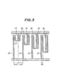
- Fig. 2 is a plan view showing a first embodiment of the surface acoustic wave transducer according to the invention.
- the transducer comprises a substrate 11 made of a piezoelectric material, input side IDT structure 12 including positive and negative electrodes which are arranged in an interdigit manner, and an output side IDT structure 13 having positive and negative electrodes also arranged in an interdigit manner.
- the short-circuit-type floating electrodes 16 are arranged such that they are closer to the negative electrodes 15. That is to say, the floating electrodes 16 are not arranged at middle points between positive and negative electrodes 14 and 15, but are provided at positions which are closer to the negative electrodes 15.
- a distance do between a center of the negative electrode 15 and a center of the floating electrode 16 is suitably determined within a range of X/12 ⁇ do ⁇ x/6.
- a phase of a wave reflected by the short-circuit-type floating electrodes is reversed to that of waves which are generated by the positive and negative electrodes, and thus the energy of the surface acoustic wave which propagates in one direction is selectively increased.
- the electrode arrangement of the input side IDT structure 12 and the electrode arrangement of the output side IDT structure 13 are symmetrical with respect to a center line L which is perpendicular to wave propagating paths and passes middle points of the wave propagating paths.
- the positive electrodes 14, negative electrodes 15 and floating electrodes 16 of the input and output side IDT structures 12 and 13 are arranged in accordance with the distance-weighting method. This will be explained more in detail.
- An area of the substrate 11 on which the positive electrodes 14, negative electrodes 15 and floating electrodes 16 of the input side IDT structure 12 constitutes an active region, and this active region is divided into a plurality of tracks T 1 , T 2 , T 3 ---T n-1 and T n .
- a length of a track measured in a direction perpendicular to the wave propagating direction That is to say, lengths of the tracks Ti, T 2 , T 3 --- T n-1 and T n and T 1 ', T 2 ', T 3 '---T n-1 ,and T n ' are represented by a 1 , a 2 , a3 --- an- 1 and an. According to the invention, these lengths a 1 , a 2 , a3 ---a n-1 and an are determined in accordance with a desired function.
- This function may be a window function such as Hamming function, Hanning function and Kaiser function.
- the substrate 11 may be made of a piezoelectric material such as LiNb0 3 , LiTa0 3 , quartz, Bi 12 GeO 20 , AIP0 4 and Li 2 B 4 O 7 .
- the floating electrodes 16 are solely formed by short-circuit-type electrodes, so that it is preferable to use the quartz having the electro-mechanical coupling constant K 2 smaller than 1 %.
- the electrodes of the unidirectional transducer using the reflection by the floating electrodes may be manufactured by a photolithography which has been well developed in the method of manufacturing semiconductor integrated circuits.
- a width of the electrodes is in a range of ⁇ /16 to x, so that a frequency lower than 300 MHz is preferable.
- the number of the electrode pairs may be reduced and the energy or power of the surface acoustic wave having the unidirectional property can be increased very much. This results in that the size of the filter can be decreased.
- the electro-mechanical coupling constant K 2 is small, the mechanical reflection due to the addition of the electrode mass is important for obtaining the unidirectional property. To this end, it is desired to provide only the short-circuit-type floating electrodes for making the mechanical reflection asymmetric as in the case of the first embodiment shown in Fig. 2.
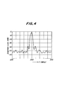
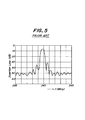
- Fig. 4 is a graph showing the frequency characteristic of the first embodiment of the surface acoustic wave transducer according to the invention illustrated in Figs. 2 and 3 and Fig. 5 is a graph representing the frequency characteristic of the known surface acoustic wave filter shown in Fig. 1.
- the number of the electrode pairs can be reduced to a great extent, and thus the size of the transducer can be made smaller than the known transducer. Further the power outside the desired frequency range can be suppressed largely and the surface acoustic wave filter having a small insertion loss can be realized.
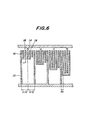
- Fig. 6 is a plan view showing a portion of a second embodiment of the surface acoustic wave transducer according to the invention.
- open-type floating electrodes 18 are arranged between the short-circuit type floating electrodes 16 and the positive and negative electrodes 14 and 15 of the input and output side IDT structures 12 and 13.
- the substrate 11 made of a piezoelectric material having the electro-mechanical coupling constant K 2 not lower than 1 %.
- Fig. 7 is a plan view depicting a portion of a third embodiment of the surface acoustic wave transducer according to the invention.
- the short-circuit-type floating electrodes 16 are connected in series with each other by means of bridging members 19 to form an integral floating electrode construction.
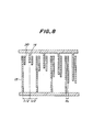
- Fig. 8 is a plan view illustrating a portion of fourth embodiment of the surface acoustic wave transducer according to the invention.
- this embodiment there are provided a plurality of open type floating electrodes 20 between successive positive and negative electrodes 14 and 15.
- the present invention is not limited to the above mentioned embodiments, but many alternations and modifications may be conceived by those skilled in the art within the scope of the invention.
- the input side IDT structure 12 and the output side IDT structure 13 are formed symmetrically with respect to the center line L, but according to the invention these IDT structures may be formed asymmetrically.
- the output side IDT structure 13 may be formed by the conventional IDT structure.
- the number of the tracks of the input side IDT structure 12 is equal to that of the output side IDT structure 13, but these numbers may be different from each other.
- the number of the tracks in the output side IDT structure may be twice of the number of the tracks in the input side IDT structure.
- the negative and positive electrodes 14 and 15 may be interchanged mutually. That is to say, the positive electrodes 14 may be called the negative electrodes and the negative electrodes 15 may be called the positive electrodes.
Landscapes
- Physics & Mathematics (AREA)
- Acoustics & Sound (AREA)
- Surface Acoustic Wave Elements And Circuit Networks Thereof (AREA)
Applications Claiming Priority (2)
| Application Number | Priority Date | Filing Date | Title |
|---|---|---|---|
| JP218498/91 | 1991-08-29 | ||
| JP03218498A JP3096102B2 (ja) | 1991-08-29 | 1991-08-29 | 弾性表面波フィルタ装置 |
Publications (3)
| Publication Number | Publication Date |
|---|---|
| EP0530041A2 true EP0530041A2 (de) | 1993-03-03 |
| EP0530041A3 EP0530041A3 (en) | 1993-08-18 |
| EP0530041B1 EP0530041B1 (de) | 1996-12-18 |
Family
ID=16720878
Family Applications (1)
| Application Number | Title | Priority Date | Filing Date |
|---|---|---|---|
| EP92307866A Expired - Lifetime EP0530041B1 (de) | 1991-08-29 | 1992-08-28 | Richtwandler mit schwebenden Elektroden für akustische Oberflächenwellen |
Country Status (4)
| Country | Link |
|---|---|
| US (1) | US5306978A (de) |
| EP (1) | EP0530041B1 (de) |
| JP (1) | JP3096102B2 (de) |
| DE (1) | DE69216007T2 (de) |
Cited By (2)
| Publication number | Priority date | Publication date | Assignee | Title |
|---|---|---|---|---|
| US5438306A (en) * | 1992-07-02 | 1995-08-01 | Kazuhiko Yamanouchi | Surface acoustic wave filter device with symmetrical electrode arrangement |
| US5773911A (en) * | 1994-09-28 | 1998-06-30 | Ngk Insulators, Ltd. | Surface acoustic wave device |
Families Citing this family (10)
| Publication number | Priority date | Publication date | Assignee | Title |
|---|---|---|---|---|
| US5406159A (en) * | 1993-11-11 | 1995-04-11 | Rf Monolithics, Inc. | Surface acoustic wave gratings having selected reflectivity |
| JP3484237B2 (ja) * | 1994-09-28 | 2004-01-06 | 日本碍子株式会社 | 弾性表面波デバイス |
| US5663695A (en) * | 1994-10-31 | 1997-09-02 | Ngk Insulators, Ltd. | Surface acoustic wave filter device and transducer therefor |
| JPH10135765A (ja) * | 1996-10-30 | 1998-05-22 | Nec Corp | 一方向性弾性表面波フィルタ |
| JP2000036722A (ja) | 1998-05-11 | 2000-02-02 | Tdk Corp | 弾性表面波装置の設計方法および弾性表面波装置 |
| WO2003038518A1 (en) | 2001-10-30 | 2003-05-08 | Pixelligent Technologies Llc | Advanced exposure techniques for programmable lithography |
| JP4561337B2 (ja) * | 2004-11-30 | 2010-10-13 | エプソントヨコム株式会社 | 一方向性弾性表面波変換器及びそれを用いた弾性表面波デバイス |
| US7836769B2 (en) * | 2006-08-10 | 2010-11-23 | Akrion Systems Llc | Apparatus and method of measuring acoustical energy applied to a substrate |
| US9726646B1 (en) * | 2013-05-29 | 2017-08-08 | National Technology & Engineering Solutions Of Sandia, Llc | Resonant surface acoustic wave chemical detector |
| US9912319B2 (en) | 2013-06-04 | 2018-03-06 | Kyocera Corporation | Duplexer and communication module |
Family Cites Families (6)
| Publication number | Priority date | Publication date | Assignee | Title |
|---|---|---|---|---|
| US4006438A (en) * | 1975-08-18 | 1977-02-01 | Amp Incorporated | Electro-acoustic surface-wave filter device |
| US4166257A (en) * | 1977-10-19 | 1979-08-28 | Motorola, Inc. | Capacitively weighted surface acoustic wave device |
| JPS5616313A (en) * | 1979-07-19 | 1981-02-17 | Kimio Shibayama | Distance-weighted type reed screen type surface elastic wave transducer |
| JPS60236312A (ja) * | 1984-05-09 | 1985-11-25 | Kazuhiko Yamanouchi | 浮き電極内部反射型一方向性弾性表面波変換器 |
| US4689586A (en) * | 1985-06-07 | 1987-08-25 | Hitachi, Ltd. | Surface elastic wave device |
| JPH0320929A (ja) * | 1989-06-16 | 1991-01-29 | Hitachi Ltd | カラー陰極線管の製造方法 |
-
1991
- 1991-08-29 JP JP03218498A patent/JP3096102B2/ja not_active Expired - Lifetime
-
1992
- 1992-08-28 DE DE69216007T patent/DE69216007T2/de not_active Expired - Fee Related
- 1992-08-28 EP EP92307866A patent/EP0530041B1/de not_active Expired - Lifetime
-
1993
- 1993-05-21 US US08/064,675 patent/US5306978A/en not_active Expired - Lifetime
Cited By (2)
| Publication number | Priority date | Publication date | Assignee | Title |
|---|---|---|---|---|
| US5438306A (en) * | 1992-07-02 | 1995-08-01 | Kazuhiko Yamanouchi | Surface acoustic wave filter device with symmetrical electrode arrangement |
| US5773911A (en) * | 1994-09-28 | 1998-06-30 | Ngk Insulators, Ltd. | Surface acoustic wave device |
Also Published As
| Publication number | Publication date |
|---|---|
| JP3096102B2 (ja) | 2000-10-10 |
| EP0530041B1 (de) | 1996-12-18 |
| DE69216007D1 (de) | 1997-01-30 |
| US5306978A (en) | 1994-04-26 |
| EP0530041A3 (en) | 1993-08-18 |
| JPH0563488A (ja) | 1993-03-12 |
| DE69216007T2 (de) | 1997-05-22 |
Similar Documents
| Publication | Publication Date | Title |
|---|---|---|
| US4910839A (en) | Method of making a single phase unidirectional surface acoustic wave transducer | |
| EP0056690B1 (de) | Akustischer Oberflächenwellenresonator | |
| US5485052A (en) | Three electrode type saw longitudinal coupling filter | |
| JP3606944B2 (ja) | Sawフィルタ | |
| US7135805B2 (en) | Surface acoustic wave transducer | |
| EP0483940B1 (de) | Einphasiger, einseitig gerichteter, gruppenförmig angeordneter Wandler mit 3/8 Lambda und 5/8 Lambda Bemusterung | |
| EP0530041B1 (de) | Richtwandler mit schwebenden Elektroden für akustische Oberflächenwellen | |
| US5438306A (en) | Surface acoustic wave filter device with symmetrical electrode arrangement | |
| US5336957A (en) | Surface acoustic wave convolver | |
| US5300902A (en) | Surface acoustic wave device for band-pass filter having small insertion loss and predetermined pass-band characteristics for broad band | |
| US5670920A (en) | Multi-track SAW filter with reflectors and reversed polarity IDT connections | |
| EP1207621B1 (de) | Transversalfilter mit akustischen Oberflächenwellen | |
| US5663696A (en) | Saw filter with wave reflections and phase differences | |
| EP0840446A2 (de) | Unidirektionales Filter mit akustischen Oberflächenwellen | |
| EP0562876B1 (de) | Akustische Oberflächenwellenfilteranordnung | |
| US5818310A (en) | Series-block and line-width weighted saw filter device | |
| US4365220A (en) | Surface wave circuit device | |
| US6967545B2 (en) | Saw wave-guides | |
| US4255726A (en) | Surface acoustic wave filter | |
| US4405874A (en) | Surface acoustic wave (saw) devices having series-connected inter-digital transducers | |
| EP0255263B1 (de) | Wandler | |
| US6559739B2 (en) | String weighted surface acoustic wave transducer | |
| Tsutsumi et al. | A novel reflector-filter using a SAW waveguide directional coupler | |
| EP0088493B1 (de) | Akustische Oberflächenwellen-Einrichtungen | |
| WO1998027647A1 (en) | Surface wave device filters using resonant single phase unidirectional transducers |
Legal Events
| Date | Code | Title | Description |
|---|---|---|---|
| PUAI | Public reference made under article 153(3) epc to a published international application that has entered the european phase |
Free format text: ORIGINAL CODE: 0009012 |
|
| AK | Designated contracting states |
Kind code of ref document: A2 Designated state(s): DE FR GB |
|
| PUAL | Search report despatched |
Free format text: ORIGINAL CODE: 0009013 |
|
| RHK1 | Main classification (correction) |
Ipc: H03H 9/145 |
|
| AK | Designated contracting states |
Kind code of ref document: A3 Designated state(s): DE FR GB |
|
| 17P | Request for examination filed |
Effective date: 19940110 |
|
| GRAG | Despatch of communication of intention to grant |
Free format text: ORIGINAL CODE: EPIDOS AGRA |
|
| 17Q | First examination report despatched |
Effective date: 19960327 |
|
| GRAH | Despatch of communication of intention to grant a patent |
Free format text: ORIGINAL CODE: EPIDOS IGRA |
|
| GRAH | Despatch of communication of intention to grant a patent |
Free format text: ORIGINAL CODE: EPIDOS IGRA |
|
| GRAA | (expected) grant |
Free format text: ORIGINAL CODE: 0009210 |
|
| AK | Designated contracting states |
Kind code of ref document: B1 Designated state(s): DE FR GB |
|
| REF | Corresponds to: |
Ref document number: 69216007 Country of ref document: DE Date of ref document: 19970130 |
|
| ET | Fr: translation filed | ||
| PLBE | No opposition filed within time limit |
Free format text: ORIGINAL CODE: 0009261 |
|
| STAA | Information on the status of an ep patent application or granted ep patent |
Free format text: STATUS: NO OPPOSITION FILED WITHIN TIME LIMIT |
|
| 26N | No opposition filed | ||
| REG | Reference to a national code |
Ref country code: GB Ref legal event code: IF02 |
|
| PGFP | Annual fee paid to national office [announced via postgrant information from national office to epo] |
Ref country code: DE Payment date: 20070831 Year of fee payment: 16 |
|
| PGFP | Annual fee paid to national office [announced via postgrant information from national office to epo] |
Ref country code: GB Payment date: 20070705 Year of fee payment: 16 |
|
| PGFP | Annual fee paid to national office [announced via postgrant information from national office to epo] |
Ref country code: FR Payment date: 20070803 Year of fee payment: 16 |
|
| GBPC | Gb: european patent ceased through non-payment of renewal fee |
Effective date: 20080828 |
|
| REG | Reference to a national code |
Ref country code: FR Ref legal event code: ST Effective date: 20090430 |
|
| PG25 | Lapsed in a contracting state [announced via postgrant information from national office to epo] |
Ref country code: FR Free format text: LAPSE BECAUSE OF NON-PAYMENT OF DUE FEES Effective date: 20080901 Ref country code: DE Free format text: LAPSE BECAUSE OF NON-PAYMENT OF DUE FEES Effective date: 20090303 |
|
| PG25 | Lapsed in a contracting state [announced via postgrant information from national office to epo] |
Ref country code: GB Free format text: LAPSE BECAUSE OF NON-PAYMENT OF DUE FEES Effective date: 20080828 |