EP0530836A1 - Appareil d'entrée de coordonnées et méthode pour la correction de coordonnées - Google Patents
Appareil d'entrée de coordonnées et méthode pour la correction de coordonnées Download PDFInfo
- Publication number
- EP0530836A1 EP0530836A1 EP92115197A EP92115197A EP0530836A1 EP 0530836 A1 EP0530836 A1 EP 0530836A1 EP 92115197 A EP92115197 A EP 92115197A EP 92115197 A EP92115197 A EP 92115197A EP 0530836 A1 EP0530836 A1 EP 0530836A1
- Authority
- EP
- European Patent Office
- Prior art keywords
- coordinate
- vibration
- inputting
- correction
- coordinates
- Prior art date
- Legal status (The legal status is an assumption and is not a legal conclusion. Google has not performed a legal analysis and makes no representation as to the accuracy of the status listed.)
- Granted
Links
Images










Classifications
-
- G—PHYSICS
- G06—COMPUTING OR CALCULATING; COUNTING
- G06F—ELECTRIC DIGITAL DATA PROCESSING
- G06F3/00—Input arrangements for transferring data to be processed into a form capable of being handled by the computer; Output arrangements for transferring data from processing unit to output unit, e.g. interface arrangements
- G06F3/01—Input arrangements or combined input and output arrangements for interaction between user and computer
- G06F3/03—Arrangements for converting the position or the displacement of a member into a coded form
- G06F3/041—Digitisers, e.g. for touch screens or touch pads, characterised by the transducing means
- G06F3/043—Digitisers, e.g. for touch screens or touch pads, characterised by the transducing means using propagating acoustic waves
- G06F3/0433—Digitisers, e.g. for touch screens or touch pads, characterised by the transducing means using propagating acoustic waves in which the acoustic waves are either generated by a movable member and propagated within a surface layer or propagated within a surface layer and captured by a movable member
Definitions
- the present invention relates to an apparatus for inputting coordinates. More particularly, the invention relates to the correction of the output in an apparatus for inputting coordinates which calculates coordinates with the propagation delay time of elastic waves.
- N i in equation (1) corresponds to an amount of deviated wavelength of which the detected phase delay time tp is deviated by a certain wavelength, and it is always an integer.
- N i is calculated from the difference between the group delay tg and the phase delay tp as expressed in the equation (1). Therefore, if, for example, the waveform is deformed by an angle at which a vibrating pen is depressed against a vibration transmission member, an offset value is generated due to deviation of the detecting point for the tg, or the like.
- Fig. 8 shows such a state as this, indicating the result of actual measurement representing the difference ⁇ N between N real arranged into an integer by equation (1) and N already arranged into the integer.
- Each of lines a, b, c, d, and e corresponds to each of inclinations of pens a, b, c, d, and e shown in Fig. 9.
- the margin for N calculation i.e., ⁇ 0.5
- the margin in positive direction is approximately + 0.3 which is approximately half + 0.5 of the c line.
- the phase velocity Vp can be one of the elements that affect the coordinate accuracy.
- This velocity Vp is related to thickness d of a propagation member and frequency f of vibration and is defined by a function of the product (f x d). Therefore, a fluctuation of the thickness upon manufacturing or a variation of the thickness within the propagating member cause the phase velocity Vp to vary, thus resulting in errors in distance between a source of vibration and sensor to lower the coordinate accuracy.
- the delay time tp is not continuous in relation to the distance.
- the delay time takes the same value t a even if distances from the sensors are known such as points at distances l1 and l2.
- the delay time must be sampled at a number of points by varying the distance from the sensor. This leads to increasing the number of manufacturing step, thus causing a cost up unavoidably.
- the detected signal waveform of the wave output from the sensor not only changes in amplitude level due to attenuation of the wave by the distance between vibrating input pen and sensor, but also depends greatly on the extent of the tool force, strong or weak, of the input pen exerted by an operator. Therefore, when the delay time is detected at a position as a specific position for signal detection where the detecting signal waveform is beyond a certain constant level (the level is required to be more than a certain constant value for distinguishing from any noise), the leading portion of the detected signal waveform cannot be detected. Instead, depending on the detected signal waveform, its second cycle (Fig. 24B) or third cycle (Fig.
- any measurement with accuracy is impossible when the distance is calculated by only group delay time.
- the relation between phase delay time and distance still remains in stepping state as shown in Fig. 25 even if a level of the detected signal waveform is made constant electrically to prevent an attenuation of sonic wave and to remove a dependency of the total force, therefore, when a value t0 is output as a delay time in Fig. 25, there arises a problem it becomes impossible to determine whether the distance is l1 or l2.
- the present invention has been made in consideration of the above-mentioned conventional examples, and the object of the invention is to provide a coordinate inputting apparatus capable of correcting errors in inputted coordinates due to inclination of an input pen so that the coordinates can be calculated more accurately.
- Fig. 1 is a view schematically showing a structure of a first embodiment of a coordinate inputting apparatus according to the present invention.
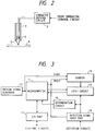
- Fig. 2 is a view schematically showing a coordinate input pen according to the first embodiment.
- Fig. 3 is a block diagram showing an operation control circuit according to the first embodiment.
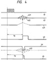
- Fig. 4 is a view for explaining states where coordinates are obtainable from propagations of elastic waves.
- Fig. 5 is a block diagram showing a structure of a waveform detecting circuit.
- Fig. 6 is an arrangement for vibration sensors according to the first embodiment.
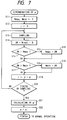
- Fig. 7 is a flowchart showing procedure to determine a correction amount.
- Fig. 8 is a graph showing fluctuations of ⁇ N for angle of a pen.
- Fig. 9 is a view showing relations between angles of a pen and a sensor.
- Fig. 10 is a graph showing an example of ⁇ N sampling.
- Fig. 11 is a graph showing an example of ⁇ N sampling after correction.
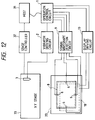
- Fig. 12 is a view schematically showing a structure of a second embodiment of a coordinate inputting apparatus according to the present invention.
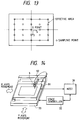
- Fig. 13 is a view showing an example of sampling for correction.
- Fig. 14 is a view showing an external appearance of a sampling apparatus.
- Fig. 15 is a flowchart showing coordinate input and correcting input by the use of operation control circuit.
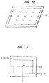
- Fig. 16 is a view showing a sampling template.
- Fig. 17 is a view showing an example of sampling technique.
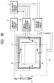
- Fig. 18 is a block diagram showing a structure of a coordinate inputting apparatus of a third embodiment according to the present invention.
- Fig. 19 is a view schematically showing an inner structure of an operation control circuit according to the third embodiment.
- Fig. 20 is a timing chart for signal processing.
- Fig. 21 is a block diagram showing a signal waveform detection circuit.
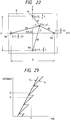
- Fig. 22 is a view showing a coordinate system of a coordinate system inputting apparatus.
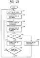
- Fig. 23 is a flowchart showing correction procedures.
- Figs. 24A to 24C are views for explaining the relations between delay times and levels of signal waveforms.
- Fig. 25 is a view for explaining phase delay time and group delay time of Lamb wave relative to distances.
- Fig. 26 is a view for explaining points at which judgments are disabled.
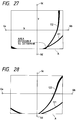
- Fig. 27 is a view for explaining an area in which judgments are disabled.
- Fig. 28 is a view for explaining removal of judgment disabled area from effective area for coordinate input.
- Fig. 29 is a graph showing the relationship between the propagation time and the propagation distance using group velocity and phase velocity as parameters.
- Fig. 1 is a view schematically showing the structure of a coordinate inputting apparatus adopting the present invention.
- the coordinate inputting apparatus shown in Fig. 1 constitutes an input and output apparatus for characters, graphics, images, and other information together with a display 18 having a displaying method of a dot matrix type or the like.
- a reference numeral 8 designates a vibration transmission plate of acrylic resin, glass, or the like to transmit vibration transmitted from a vibrating pen 3 to four vibration sensors 6 arranged on the periphery thereof.
- the coordinate of the vibrating pen 3 on the vibration transmission plate 8 are detected by measuring the transmitting time of ultrasonic vibration transmitted from the vibrating pen 3 to the vibration sensors 6 through the vibration transmission plate 8.
- the vibration transmission plate 8 is arranged on a display 18 capable of conducting dot representations such as a CRT (or a liquid crystal display), so that dot representation is given to a position traced by the vibrating pen 3.
- dot representation is executed at the position on the display 18 corresponding to the detected coordinate of the vibrating pen 3, and the images composed of the points, lines, and other elements inputted by the vibrating pen 3 will appear, following the geometric locus of the vibrating pen as if written on a sheet of paper.
- a menu display is performed on the display 18.
- the items on the menu can be selected by the vibrating pen, or an input method may also be employed so as to display a prompt to enable the vibrating pen 3 to contact with a given position.
- the vibrating pen 3 for transmitting ultrasonic vibrations to the vibration transmission plate 8 has a vibrator 4 comprising piezoelectric element and others therein, and the ultrasonic vibration generated by the vibrator 4 are transmitted to the vibration transmission plate 8 through a horn portion 5 having a pointed leading end.
- Fig. 2 is a view showing the structure of the vibrating pen 3.
- the vibrator 4 incorporated in the vibrating pen 3 is driven by a vibrator driving circuit 2.
- the driving signal for the vibrator 4 is supplied from an operation control circuit 1 in Fig. 1 as a low level pulse signal, and applied to the vibrator 4 after having been amplified with a given gain by the vibrator driving circuit 2 capable of executing low impedance driving.
- the electrical driving signal is converted into mechanical ultrasonic vibration by the vibrator 4 and the vibration is transmitted to the vibrating plate 8 through the horn portion 5.
- the vibration frequency of the vibrator 4 is selected to be a value in which Lamb wave can be generated on the vibration transmission plate 8. Also, when the vibrator is driven, a vibration mode is selected so that the vibrator 4 can be vibrated mainly in a direction perpendicular to paper surface of Fig. 2 with respect to the vibration transmission plate 8. Further, it is possible to execute an efficient vibration conversion by making the vibration frequency of the vibrator 4 a resonance frequency of the vibrator 4.
- the elastic wave thus transmitted to the vibration transmission plate 8 is Lamb wave, which has an advantage that it can hardly be affected by surface flaw or obstacle on the surface of the vibration transmission plate 8 as compared with the surface wave and others.
- the vibration sensor 6 arranged at the periphery of the vibration transmission plate 8 is also structured with an electromechanical transducer such as piezoelectric element.
- Each of the output signals of the four vibration sensors 6 is inputted into the waveform detection circuit 9 and is converted into detection signal processable in the operation control circuit 1 arranged in following state.
- the operation control circuit 1 executes the measuring process of vibration transmitting time to detect the coordinate position of the vibrating pen 3 on the vibration transmission plate 8.
- the detected coordinate information of the vibrating pen 3 is processed in the operation control circuit 1 in accordance with the output system of the display 18.
- the operation control circuit controls the output operation of the display 18 through the display driving circuit 10 on the basis of the coordinate which has been inputted.
- Fig. 3 is a diagram showing the structure of the operation control circuit 1 shown in Fig. 1.
- the structures of the driving system for the vibrating pen 3 and the vibration detecting system for the vibration sensors 6 are mainly shown.
- a microcomputer 11 has an inner counter, ROM and RAM incorporated therein.
- a driving signal generating circuit 12 outputs driving pulses of a given frequency to the vibrator driving circuit 2 shown in Fig. 1. This circuit is actuated by the microcomputer 11 in synchronism with a coordinate calculation circuit.
- the counted value of a counter 13 is latched by the microcomputer 11 to a latch circuit 14.
- the waveform detection circuit 9 outputs a timing information of the detection signal for measuring the vibration transmitting time for coordinate detection in accordance with the output from the vibration sensors 6 as described later. Each timing information is inputted into an input port 15 respectively.
- the timing signals from the waveform detection circuit 9 are inputted into the input port 15 and are stored in the storage areas in the latch circuit 14 corresponding to the respective vibratory sensors 6, the results of which are transmitted to the microcomputer 11.
- the vibration transmitting time is expressed as a latch value of the output data of the counter 13, and the coordinate operation is executed by the value of the vibration transmitting time.
- a determination circuit 16 determines whether all the timing informations from a plurality of the vibration sensors 6 have been inputted or not, and notifies the microcomputer 11 accordingly.
- the output control process of the display 18 is performed through an input/output port 17.
- Fig. 4 is a view illustrating the detection waveforms inputted into the waveform detection circuit 9 shown in Fig. 1 and the measurement processes of the vibration transmitting time on the basis of such waveforms.
- a reference numeral 41 designates a driving pulse to be applied to the vibrating pen 3.
- the ultrasonic vibration transmitted to the vibration transmission plate 8 from the vibrating pen 3 being driven by such waveform are detected by the vibration sensors 6 through the vibration transmission plate 8.
- a reference numeral 42 designates a signal waveform detected by the vibration sensor 6.
- Lamb wave used in the present embodiment is a dispersant, therefore, the relation between envelope 421 and phase 422 of the detected waveform varies in accordance with the vibration transmitting distance.
- an advancing velocity of the envelope is given as its group velocity Vg, and phase velocity Vp. With the difference between the group velocity and phase velocity, it is possible to detect the distance between the vibrating pen 3 and vibration sensor 6.
- waveform detection circuit 9 can be structured as shown in Fig. 5, for example.
- the output signals of the vibration sensors 6 are amplified to a given level by said amplifying circuit 51.
- the amplified signals are inputted into an envelope detection circuit 52 to extract only the envelope of the detection signals.
- the timing of the envelope peak extracted is detected by an envelope peak detection circuit 53.
- the envelope delay time detection signal Tg of a given waveform is produced by a signal detection circuit 54 comprising a mono-multi vibrator and others, and is inputted into the operation control circuit 1.
- phase delay time detection signal Tp is produced by a detection circuit 58 in accordance with the timing of this signal Tg and the original signal which has been delayed by a delay time adjustment circuit 57, and is inputted into the operation control circuit 1.
- the Tg signal is converted into pulse of a given width by a monostable multivibrator 55.
- a comparative level supply circuit 56 produces a threshold value with which to detect the signal Tp in accordance with this pulse timing.
- the comparative level supply circuit 56 produces a signal 44 having the level and timing shown by a reference numeral 44 in Fig. 4, and inputs such signal into the detection circuit 57.
- the monostable multivibrator 55 and comparative level supply circuit 56 serve to allow the measurement of the phase delay time to be carried out only for a given period subsequent to the envelope peak detection.
- This signal is inputted into a detection circuit 58 comprising a comparator and others, and is compared with the detection waveform which has been delayed as shown in Fig. 4. Consequently, a Tp detection pulse such as shown by reference numeral 45 in Fig. 4 is produced.
- each h numbers of the detection signals of the envelope delay times Tgl to h, and phase delay times Tpl to h are inputted into the operation control circuit 1, respectively.
- the above-mentioned signals Tgl to h and Tpl to h are inputted into the input port 15. Then, drawing each timing, the counted values of the counter 13 are latched into the latch circuit 14, respectively. As described earlier, the counter 13 is started in synchronism with the vibrating pen, thus the data indicating each delay time for the envelope and the phase are latched into the latch circuit 14.
- the coordinate (x, y) of the position P of the vibrating pen 3 can be obtained by the theorem of three squares on the basis of D l , D r , D u , and D d .
- N i [(vg ⁇ tg i -vp ⁇ tP i )/ ⁇ + ⁇ ] (5 )
- D i vp ⁇ tp i + N i ⁇ (6)
- x (D12-D r 2)/2X RL + (D1-D r )/2
- y (D u 2-D d 2)/2Y UD + (D u -D d )/2 (8)
- N is a number for correcting a difference between a distance for the group velocity delay and a distance for the phase velocity delay with respect to the calculated distance from the vibration propagating delay times, and is given as integer.
- N is fundamentally a quantity given as integer, it does not necessarily become an integer only by the first item in [ ] of the equation (5) due to measurement errors and the like. Therefore, an correcting amount ⁇ is added in order to make it an integer. Because of this, the coordinate actually calculated is (x', y') which includes errors in making N an integer. For its simple correction to approximate it to the real coordinate (x, y), the following method is employed:
- N [ ⁇ (vg/vp)tg-tp ⁇ / ⁇ + ⁇ ]; an integer expressed in [ ] (9)
- N REAL ⁇ (vg/vp)tg-tp ⁇ / ⁇ + ⁇ (10)
- ⁇ N N REAL - N (11)
- the value of ⁇ value should be modified by making the central value of ⁇ N fluctuations as zero.
- ⁇ ' ⁇ - ⁇ ( ⁇ N max - ⁇ N min )/2 + ⁇ N min ⁇ (12)
- the ⁇ can be a value used when ⁇ N is calculated.
- Fig. 7 is a flowchart showing the procedure embodying a method for determining a correction amount ⁇ ' using said equation (12).
- steps S11 and S12 variables N max and N min are initialised. A counter i for counting sampling numbers is also cleared. To the variables N max and N min , the maximum value and minimum value of ⁇ N are assigned, respectively.
- the sampling is started in step S13.
- the sampling is executed by selecting the appropriate coordinates, and the coordinates are inputted at such positions.
- the group delay time tg and phase delay time tp are measured at each of the sensors S XL , S XR , S YU , and S YD arranged at the edges of the vibration transmission plate.
- step S14 the ⁇ N is obtained by the equations (9), (10), and (11) using the measured values tp and tg.
- the values vp, vg, and ⁇ are assumed to have been known.
- step S15 whether obtained ⁇ N is greater than the current value of N max or not is determined. If it is found greater, ⁇ N is assigned to N max (step S16). Likewise in step S17, whether ⁇ N is smaller than N min or not is determined, and if it is found smaller, the value thus found is assigned to the N min (step S18).
- step S19 When one sampling data is processed, the counter i for counting the sampling numbers is incrementated by 1 in step S19 and then in step S20, whether the value of the counter i has arrived at a given sampling number or not is determined. If the value has not arrived at it as yet, the process will return to the step S13 to execute the processing of another sampling data.
- an ⁇ ' is defined in step S21 by the equation (12) using the minimum and maximum ⁇ Ns hitherto obtained. Thus, thereafter, the coordinate calculation will be performed with this ⁇ ' as ⁇ (step S22).
- sampling numbers in the above-mentioned procedures are arbitrary.
- the numbers can be set to obtain a desired accuracy.
- the sampling period is regulated by the sampling numbers, but it may be possible to regulate it by time or other means.
- ⁇ ' is determined using the procedures in accordance with the above-mentioned flowchart.
- appropriate characters or graphics are written on the coordinate input plate by the user freehand or according to a format prepared in advance. As sampling data, a date, various figures (circle, square, and the like) or many other patterns are inputted, for example. Thus, the value of ⁇ ' can be obtained in a better condition.
- the mode for determining a correction amount ⁇ ' by calculating ⁇ N is actuated by explicitly instructing it in the first embodiment, it may be possible to do this during the operation of a normal coordinate input without causing a user to select this mode.
- ⁇ N is calculated at each time the coordinates are normally inputted, and whenever the samplings are accumulated to a given number, a correction amount ⁇ is calculated to update its value. If the structure is arranged in such a manner it is possible to correct the coordinate calculation without any sampling operation executed by a user. Moreover, since ⁇ N is frequently calculated like this, it becomes possible to determine the adequateness of the calculated coordinate values. In other words, when the inputted coordinates are calculated, its ⁇ N for each of the sensors is calculated.
- this ⁇ N value is the one close to ⁇ 0.5, that is, the margin is close to zero, it can be determined that there is a high possibility that this data will bring about errors in any coordinated values obtained.
- a ⁇ N which exceeds a predetermined ⁇ N th threshold value is calculated, it is possible to eliminate any erroneous output by nullifying the coordinate value inputted at that time.
- the value of the ⁇ N th threshold value may be determined by the maximum values and minimum values of ⁇ N samplings to be conducted at the time of delivery, for example. Also, it may be possible to determine the threshold value using a statistical technique for the sampled data groups within a range of integral times the standard deviations with its mean value as the central value, for example. Also, it may be possible to define the threshold value specifically as a constant without making any individual determination for each mechanical body of the apparatuses.
- the present invention is applicable not only to an apparatus comprising a plurality of equipment, but also to an apparatus having a single equipment.
- the present invention is, of course, applicable to a case where a system or an apparatus is operative when a program is supplied thereto.
- a coordinate inputting apparatus is capable of correcting errors in the inputted coordinates due to the inclination of the input pen and calculating the coordinates more accurately.
- Fig. 12 is a view showing the structure of a second embodiment of a coordinate inputting apparatus according to the present invention.
- the structure of the main body of the coordinate inputting apparatus is the same as the first embodiment shown in Fig. 1. Because the descriptions of the operation control circuit and the coordinate calculation are duplicated, these descriptions will be omitted.
- an X-Y stage is connected for inputting the coordinates which are known in advance in order to correct the coordinates to be output.
- the X-Y stage 33 is one to cause the coordinate positions specified by a vibrating pen 3 to be indicated, and when a host 31 indicates coordinates, a stage controller 32 determines an amount for the vibrating pen 3 to move. Then, the X-Y stage 33, having received such as indication, allows the vibrating pen to move to a new position.
- the host 31 is connected to the coordinate inputting apparatus through communication lines to transmit and receive data.
- Fig. 14 is a view showing the appearance of a coordinate inputting apparatus to which an X-Y stage is connected.
- a reference numeral 91 designates the main body of the coordinate inputting apparatus; 3, a vibrating pen for input which is connected to an arm 92; and 33, the X-Y stage movable in the directions of the X axis and Y axis which are orthogonal to each other and is controlled by the host 31 through the controller 32, thus being movable to specified positions.
- the indicated coordinates (x, y) can be obtained by the above-mentioned equations (5) to (8), but the values actually calculated are (x', y') which include errors due to the fluctuation of the phase velocity Vp.
- a method is used in the second embodiment as given below.
- Vp is separated by defining the propagation delay times for the sensors S XL and S XR as t l and t r and then it can be expressed as follows.
- x vp2 ⁇ (t l 2-t r 2)/2X RL + vp ⁇ (t l -t r )/2 (14)
- t u and t d are the delay times for sensors S YU and S YD .
- i l, r, u, and d.
- K (l + ⁇ K)
- the velocity variation should be approximately 1.5%.
- ⁇ K ⁇ 0.015. Therefore, it can be expressed by the equation (20) as follows. x/x' ⁇ l/K (21)
- the variation of the phase velocity Vp is absorbed by multiplying the output coordinate value x' by a correction coefficient l/K, thus making is possible to calculate accurate coordinates.
- the output coordinate for the coordinate position including the extreme edges of the effective area is sampled by the equations (21) and (23), and then it is clear that the correction coefficient l/K can be determined by calculating the average of the ratios (x/x') and (y/y').
- the point where coordinate position (denominator) becomes zero is removed because the calculation is disable.
- the output coordinate is sampled using the X-Y stage.
- the coordinate (x, y) is specified by the host 31 to the stage controller 32.
- the specified coordinate is given as values with the center of the coordinate inputting apparatus as origin (zero adjustment point: refer to Fig. 6).
- the positions represented by small circles (sampling points) in Fig. 13 are specified as such coordinate (X i , Y i ), and then the coordinate (X i ', Y i ') calculated after inputted by the vibrating pen 3 is obtained from the main body of a coordinate inputting apparatus 91.
- the host 31 has already transmitted the specified coordinate (X i , Y i ) to the main body of the coordinate inputting apparatus 91.
- the operation control circuit 1 in the main body 91 obtains a correction constant K i by applying the equations (21) and (23) using the transmitted values together with the calculated coordinate (X i ', Y i ').
- the above-mentioned process is executed at various coordinate positions plural times. For example, it is performed at each of the sampling points in Fig. 13.
- the values K i thus obtained are all averaged to be the correction constant K.
- the correction constant K thus obtained may be stored in a memory or the like in the operation control circuit 1. In this respect, it is impossible for the usual coordinate input to conduct the sampling at the coordinate positions for the K calculations. It is thus particularly necessary to provide an input mode for calculating correction data.
- x x' / K
- y y' / K
- the current input mode is examined (S111).
- the input mode is specified by a personal computer or other controlling equipment connected to a coordinate inputting apparatus according to the present embodiment or specified by switches or others provided for the main body of the coordinate inputting apparatus.
- the coordinate is calculated by the vibration delay times, and corrected values are output (S112).
- the correction is made by the equations (24) and (25) using the correction constant K defined by the correction input mode.
- the variables i and K for the use of calculations are initialized at first (S113), then whether the correction input is revised or not is tested (S113'). If not revised, coordinate (x i ', y i ') is calculated. For this, the equations (16) and (17) are used (S114). Meanwhile, in this case, the inputted coordinate has already been known. Therefore, such coordinate (x i , y i ) is obtained from the host 11 of the X-Y state (S115).
- the correction constant K i is calculated using the equations (21) and (23). Since two values, (x i '/x i ) and (y i '/y i ), are obtained from one coordinates, its mean value is adopted as K i (S116).
- the host 31 may be possible for the host 31 to read output (x', y') of the main body 91 of the coordinate inputting apparatus on the contrary and calculate the correction constant K which will be transmitted to the main body of the coordinate inputting apparatus.
- the procedures shown in the flowchart in Fig. 15 can still be executed by the host 31 as they are.
- the coordinate (x i ', y i ') must be read from the main body of the coordinate inputting apparatus while in the step S115, it becomes unnecessary to fetch the coordinate (x i , y i ).
- the obtained K value must be transmitted to the main body of the coordinate inputting apparatus and stored in a memory.
- another apparatus is externally connected to the coordinate inputting apparatus to obtain and calculate correction data, but it may be possible to do these in the main body of the coordinate inputting apparatus.
- a template 110 as shown in Fig. 16 is prepared. Using it as a jig which supports each input at a given position, the sampling input operations are executed.
- the template 110 is of the same size of the coordinate inputting area. With the aid of the holes provided at appropriate positions, the indications can be made with the input pen through such holes.
- a mode is switched over by a menu selection or switching to the correction input mode, and the template is set at a fiducial position on the coordinate inputting area.
- the template may be set with the exterior of the main body of the coordinate inputting apparatus as reference, or if it is a type integrally built with a display, it may be possible to display a cross-line type or some other fiducial marks for setting on the image formation surface.
- setting the template for sampling inputs the calculations are performed by the equations (21) and (23) using the coordinate data calculated at that time and the positions of the holes on the template which are given in advance, or coordinate values, hence adopting the average of the results of these calculations as in the case of the aforesaid conventional example.
- the two points, P1 and P2, shown in Fig. 17 are sampled using a template capable of covering such two points. Then, it may be possible to determine K by the equations (26) and (27) using the difference between them. Also, it may be possible to use a template having hole positions regulated with cycles of predetermined intervals thereby to conduct inputs sequentially per row from the starting point. Then, calculations are performed on the basis of the difference between the coordinates adjacent to each other. When the number of holes per row or the difference between given data is found to be above the fiducial value (two times X1 - X2, for example), it is considered that the rows are to be changed, and the rows can be changed just by conducting recalculation between the adjacent points themselves.
- a tg is detected to enable it to serve as vg dually.
- a coordinate inputting apparatus is capable of correcting the outputting coordinates with ease, hence providing a method for correcting coordinate positions, which enables coordinate inputs to be performed with high precisions, as well as a coordinate inputting apparatus capable of implementing such a method.
- Fig. 18 shows the structure of a coordinate inputting apparatus according to a third embodiment of the present invention.
- a reference numeral 1 designates an operation control circuit which controls the entire system of the apparatus as well as calculates the coordinate positions; 2, a vibrator circuit to drive the tip of the pen in a vibrating pen 3; and 8, a vibration transmitting diaphragm made of a transparent material such as acrylic resin or glass, and the coordinate input by the vibrating pen 3 is performed by allowing it to touch the surface of the vibration transmitting diaphragm 8.
- it is done by specifying the locations with the vibrating pen 3 within the area at a reference mark A indicated by solid line in Fig. 18 (hereinafter, referred to as effective area).
- an anti-vibration material 7 is provided to prevent (reduce) the rebounding vibration from being returned to the central part, and on the boundary portion therebetween there are fixed the vibratory sensors 6a to 6d which transduce mechanical vibrations to electric signals such as piezoelectric elements.
- a reference numeral 9 designates a signal waveform circuit for outputting the vibration signals detected by the respective sensors 6a to 6d to the operation control circuit 1, and 11, a display capable of performing displays per dot unit for a liquid crystal display or the like, which is arranged behind the vibration transmitting diaphragm, thus displaying dots at the positions traced by the vibrating pen 3 driven by a display driving circuit 10.
- Such a display can be observed through the vibration transmission plate 8 (made of transparent material).
- the vibrator 4 incorporated in the vibrating pen 3 is driven by the vibrator driving circuit 2.
- the driving signals for the vibrator 4 are supplied from the operation control circuit 1 as low level pulse signals, and subsequent to having been amplified by the vibrator driving circuit 2 with a given gain, the driving signals are applied to the vibrator 4.
- the electric driving signals are transduced by the vibrator 4 into mechanical ultrasonic vibration and are transmitted to the vibration transmission plate 8 through the tip 5 of the pen.
- the operation control circuit 1 outputs and signals which drive the vibrator 4 to the vibrator driving circuit 2 and the vibrating pen 3 per given cycle (per 5 ms, for example) and at the same time, causes its inner timer (comprising a counter) to start clocking. Then, the vibration generated by the vibrating pen 3 arrives at the vibratory sensors 6a to 6d with delays depending on the distances therebetween.
- the vibration waveform detection circuit 9 detects signals from each of the vibratory sensors 6a to 6d and generates the signals which represent the vibration arrival timing to each of the vibration sensors by the waveform detection processing which will be described later.
- the operation control circuit 1 inputs the signals per sensor to detect the vibration arrival time to each of the vibration sensors 6a to 6d and calculates the coordinate positions of the vibrating pen.
- the operation control circuit 1 drives the display driving circuit 10 on the basis of the positional information of the vibrating pen 3 which has been calculated to control displaying by the display 11 or output the coordinate to external equipment (not shown) by means of serial or parallel communications.
- Fig. 19 is a block diagram schematically showing the structure of the operation control circuit 1 according to the present embodiment. Each constituent and the outline of its operation will be set forth below.
- a reference numeral 11 designates the operation control circuit 1 and a microcomputer for controlling the entire system of the coordinate inputting apparatus embodying the present invention, which comprises an inner counter, ROM for storing the operational procedures, RAM used for calculation and others, and a non-volatile memory and others for storing constant and the like.
- a reference numeral 13 designates a timer (comprising a counter, for example) measuring the standard clocking which is not shown and starts its clocking when the starting signal is inputted into the vibrator driving circuit 2 to start driving the vibrator 4 in the vibrating pen 3.
- the start of the clocking is synchronized with the detection of vibrations by the sensors, thus making it possible to measure the delay times until the vibrations are detected by the sensors (6a to 6d).
- the vibration arrival timing signal of each of the vibration sensors 6a to 6d output from the signal waveform detection circuit 9 is inputted into latch circuits 14a to 14d through the detection signal input port 15.
- Each of the latch circuits 14a to 14d is related to each of the vibration sensors 6a to 6d, and when receiving timing signals from the related sensors, they will latch the timing value of the timer 13.
- the determination circuit 16 having determined that all the detection signals are received, outputs a signal to the microcomputer 11 to indicate the situation accordingly.
- the microcomputer 11 reads from the latch circuits the vibration arrival times from the latch circuits 14a to 14d to each of the vibration sensors, and executes given calculations to calculate the coordinate positions of the vibrating pen 3 on the vibration transmitting diaphragm 8.
- the calculated coordinate positional information is output to the display driving circuit 10 through the I/O port 17, thus displaying dots or the like at the corresponding positions on the display 11, for example, or the coordinate positional information is output to an interface circuit through the I/O port 17 thereby to output the coordinate values to the external equipment.
- Fig. 20 is a view illustrating the detection waveforms inputted into the signal waveform detection circuit 9 and the measurement processes for the vibration transmitting times on the basis of such waveforms.
- the description will be made of a case related to the vibration sensor 6a. It is to be understood that the same will be applicable to the other vibration sensors 6b, 6c, and 6d exactly.
- the measurement of vibration transmitting time to the vibration sensor 6a is started at the same time that the starting signal is output to the vibrator driving circuit 2.
- the driving signal 41 is being applied to the vibrator 4 from the vibrator driving circuit 2.
- the ultrasonic vibration transmitted to the vibration transmitting diaphragm 8 from the vibrating pen 3 is detected by the vibration sensor 6a after they have advanced while taking a time tg corresponding to the distance to the vibratory sensor 6a.
- the signal at 42 in Fig. 20 shows the signal waveform detected by the vibration sensor 6a.
- the vibrations used for the present embodiment are of lamb waves
- the relation between the envelope 421 and phase 422 of the detection waveform relative to the propagation distance in the vibrating transmission plate 8 varies during the transmission of the vibrations in accordance with its transmitting distance.
- the advancing velocity of the envelope 421 that is, the group velocity
- Vg the advancing velocity of the envelope 421
- Vp the phase velocity of the phase 422
- the process will be given on the basis of the phase signal detection.
- a specific detection point on the phase waveform signal 422 such as a time arriving at a zero cross point after a certain predetermined signal level 46, as Tp 45 (which can be obtained by generating a window signal 44 having a specific width with respect to the signal 47 and comparing it with the phase signal 422)
- Tp 45 which can be obtained by generating a window signal 44 having a specific width with respect to the signal 47 and comparing it with the phase signal 422
- n int [(Vg ⁇ Tg-Vp ⁇ Tp) / ⁇ P + 1/N]
- N is a real number other than zero, and any appropriate number can be used.
- N 2
- an n can be defined, provided that the variations of tg and others are within ⁇ 1/2 wavelength.
- the generations of the signals 43 and 45 for the measurements of the above-mentioned two vibration transmitting times tg and tp are executed by a vibration waveform detection circuit 9.
- This vibration waveform detection circuit 9 is structured as shown in Fig. 21.
- Fig. 21 is a block diagram showing the structure of the vibration waveform detection circuit 9 according to the third embodiment.
- the output signals of the vibration sensor 6a are amplified by a preamplifier 61 to a given level.
- the excessive frequency components of the amplified signals are removed by a band pass filter 62 and are inputted into an envelope detection circuit 63 comprising an absolute value circuit, a low band pass filter, and others, for example.
- an envelope detection circuit 63 comprising an absolute value circuit, a low band pass filter, and others, for example.
- the envelopes of a detection signal are drawn.
- the timing of envelope peak is detected by an envelope peak detection circuit 64.
- the signal tg (signal 43 in Fig. 20), which is the envelope delay detection signal having a given waveform is produced by a tg signal detection circuit 65 comprising a mono vibrator and others on the basis of the envelopes detected by the peak detection circuit, is inputted into the operation control circuit 1.
- a reference numeral 66 designates a signal detection circuit which forms pulse signals 47 for the portion exceeding a threshold signal 46 of a given level in the envelope signal 421 detected by the envelope detection circuit 63; 67, a monostable multivibrator to open the gate signal 44 of a given time width triggered by the initial rise of the pulse signals 47; and 68, a Tp comparator to detect the zero cross point of the initially rising phase signal 422 during the period the gate signal 44 is open thereby to supply the phase delay time signal tp 45 to the operation control circuit 1.
- the circuits described above are for the vibration sensor 6a, but the same circuit is provided for each of the other vibration sensors.
- the vibration transmitting time latched by the aforesaid latch circuit includes a circuit delay time et and a phase offset time (toff).
- et circuit delay time
- toff phase offset time
- the distance from the vibration sensor 6a to the origin 0 is stored in the non-volatile memory in advance and is known, the distance between the vibrating pen 3 and the vibration sensor 6a can be determined. It is also possible to obtain such distance for each of the other sensors 6b to 6d in the same manner.
- each of the four vibration sensors 6a to 6d is arranged at the positions designated by reference marks S1 to S4, respectively. Then, it is possible to obtain the straight distances da to dd from the position P of the vibrating pen 3 to the positions of the sensors 6a to 6d.
- the positional coordinate of the vibrating pen 3 can be detected on real time.
- the sensors a and b the x coordinate and by the sensors c and d, the y coordinate are respectively calculated independently.
- the error combinations of n, n + 1 can be prepared for 16 sorts including correct one (where all the outputs are n). With respect to the 15 combinations including errors, the length equivalent to one wavelength portion is subtracted sequentially form the output distances to calculate coordinates and examine errors. Then, the correct combinations are determined.
- coefficients A, B, C, and D are defined as 15 sorts given below.
- correction coefficient the distance correction is made by the following equations to calculate coordinate, and calculations will be repeated for all the above-mentioned combinations until succeeding in the error examination.
- Fig. 23 is a flowchart showing the processing procedures executed by the operation control circuit 1 when the above-mentioned error detections and correction processes are performed.
- This first coordinate calculation is the one performed with the data obtained in the step S71 as they are.
- the distance correction will be made by the equations (42) to (45) following the sequence of the above-mentioned (41) (S75 ⁇ S76 ⁇ S78 ⁇ S73). In this case, if the results are still unacceptable even when all the combinations have been examined (the examinations have been completed up to [1,1,1,1]), it is determined that correction is impossible and the process will proceed to obtain the next data without performing any coordinate output (S78 - YES).
- the distance corrections are made on the basis of the results of the error examinations, thus making it possible to execute the highly precise coordinate outputs without omission of any coordinate rows.
- the present embodiment is applicable to an apparatus capable of calculating coordinates with a plurality of fiducial distances provided.
- the sequence in which the distance corrections are executed is predetermined by the correction coefficients (41).
- the sequence in which the distance corrections are executed is predetermined by the correction coefficients (41).
- means for rearranging the orders of the combinations is provided, it is possible to shorten the time required for completing the corrections.
- n n - int (n) (46)
- This ⁇ n takes a value within a range of ⁇ 0.5, and if it exceeds ⁇ 0.5, a wavelength error will be generated.
- the present embodiment is an example in which the attention is given to ⁇ n for the rearrangement of the correction coefficients, but it may be possible to make the rearrangement in accordance with signal levels or other references.
- the distance corrections on the basis of the results of the examinations regarding the presence of errors, the wavelength errors generated due to the inclination of the pen or the like can be corrected.
- Fig. 26 is a view showing an example of such a case.
- the equations (54) and (55) express the conditions under which the equations (39) and (40) are satisfied when the distances between the coordinates deviated due to the wavelength errors and the fundamentally correct coordinates are equal to the product of the distances between the sensors used for the coordinate calculation and the difference between the correct and erroneous coordinates.
- the examination disabled area will be at the following coordinate positions: - Eth ⁇ (x'2+y'2)-(x2+y2)-(x'-x) ⁇ X ⁇ Eth (56) - Eth ⁇ (x'2+y'2)-(x2+y2)-(y'-y) ⁇ Y ⁇ Eth (57) If the threshold value Eth becomes greater, its area will also become greater as a matter of course.
- Reference numerals 111 and 112 in Fig. 27 designate the coordinate areas where the equations (56) and (57) are respectively satisfied when they take Eth values appropriately and then the point where they intersect constitutes the area where the examination is disabled.
- the sensor position is determined in accordance with the equations (56) and (57) so that the examination disabled area is located outside the effective area and then the X and Y are defined.
- Fig. 28 is a view showing an examination disabled area when the distances between the sensors are modified in accordance with the equations (54) and (55).
- the intersecting point at 121 and 122 is now outside the effective area.
- the examination is possible over the entire area.
- the countermeasure is taken by making the X longer and the Y shorter, but if the sensor positions are regulated, it may be possible to cope with the situation by modifying the effective area.
- the present invention is not only applicable to a system comprising a plurality of equipment but also to an apparatus comprising a single equipment. Also, the present invention will, of course, be applicable to a system or an apparatus which becomes operative by providing a program.
- a coordinate inputting apparatus of the third embodiment according to the present invention has an effect that while controlling the generations of the wavelength errors, it will not reduce useability in operation.
Landscapes
- Engineering & Computer Science (AREA)
- Physics & Mathematics (AREA)
- General Engineering & Computer Science (AREA)
- Theoretical Computer Science (AREA)
- Acoustics & Sound (AREA)
- Human Computer Interaction (AREA)
- General Physics & Mathematics (AREA)
- Position Input By Displaying (AREA)
- Length Measuring Devices With Unspecified Measuring Means (AREA)
Applications Claiming Priority (6)
| Application Number | Priority Date | Filing Date | Title |
|---|---|---|---|
| JP226788/91 | 1991-09-06 | ||
| JP3226789A JPH0566879A (ja) | 1991-09-06 | 1991-09-06 | 入力座標の補正方法及びその装置及び座標入力装置 |
| JP22678891A JP3071254B2 (ja) | 1991-09-06 | 1991-09-06 | 座標入力装置及び方法 |
| JP226789/91 | 1991-09-06 | ||
| JP456492A JP3122509B2 (ja) | 1992-01-14 | 1992-01-14 | 座標入力装置及び方法 |
| JP4564/92 | 1992-01-14 |
Publications (2)
| Publication Number | Publication Date |
|---|---|
| EP0530836A1 true EP0530836A1 (fr) | 1993-03-10 |
| EP0530836B1 EP0530836B1 (fr) | 1997-01-15 |
Family
ID=27276343
Family Applications (1)
| Application Number | Title | Priority Date | Filing Date |
|---|---|---|---|
| EP92115197A Expired - Lifetime EP0530836B1 (fr) | 1991-09-06 | 1992-09-04 | Appareil d'entrée de coordonnées et méthode pour la correction de coordonnées |
Country Status (3)
| Country | Link |
|---|---|
| US (1) | US5420804A (fr) |
| EP (1) | EP0530836B1 (fr) |
| DE (1) | DE69216724T2 (fr) |
Cited By (2)
| Publication number | Priority date | Publication date | Assignee | Title |
|---|---|---|---|---|
| EP0623892A1 (fr) * | 1993-05-07 | 1994-11-09 | Canon Kabushiki Kaisha | Appareil et procédé d'entrée de coordonnées |
| US5484967A (en) * | 1992-10-01 | 1996-01-16 | Canon Kabushiki Kaisha | Coordinate input apparatus |
Families Citing this family (17)
| Publication number | Priority date | Publication date | Assignee | Title |
|---|---|---|---|---|
| US5606346A (en) * | 1992-12-22 | 1997-02-25 | Matsushita Electric Industrial Co., Ltd. | Coordinate input device |
| JP3244895B2 (ja) * | 1993-12-02 | 2002-01-07 | キヤノン株式会社 | 距離測定装置及びそれを用いた座標入力装置、及び距離測定方法及びそれを用いた座標入力方法 |
| JP3491936B2 (ja) * | 1993-12-02 | 2004-02-03 | キヤノン株式会社 | 距離測定装置及びそれを用いた座標入力装置、及び距離測定方法及びそれを用いた座標入力方法 |
| DE4342312A1 (de) * | 1993-12-11 | 1995-06-14 | Zeiss Carl Fa | Verfahren zur Korrektur von schwingungsbedingten Meßfehlern bei Koordinatenmeßgeräten |
| JPH11249803A (ja) * | 1998-03-03 | 1999-09-17 | Canon Inc | 座標入力装置及びその制御方法、コンピュータ可読メモリ |
| EP1596160A1 (fr) * | 2004-05-10 | 2005-11-16 | Hexagon Metrology AB | Procédé d'inspection d'une pièce par une machine de mesure |
| US7499039B2 (en) * | 2005-01-10 | 2009-03-03 | 3M Innovative Properties Company | Iterative method for determining touch location |
| US9201556B2 (en) * | 2006-11-08 | 2015-12-01 | 3M Innovative Properties Company | Touch location sensing system and method employing sensor data fitting to a predefined curve |
| US8207944B2 (en) * | 2006-12-19 | 2012-06-26 | 3M Innovative Properties Company | Capacitance measuring circuit and method |
| US7956851B2 (en) * | 2006-12-20 | 2011-06-07 | 3M Innovative Properties Company | Self-tuning drive source employing input impedance phase detection |
| US8134542B2 (en) * | 2006-12-20 | 2012-03-13 | 3M Innovative Properties Company | Untethered stylus employing separate communication and power channels |
| US8040329B2 (en) | 2006-12-20 | 2011-10-18 | 3M Innovative Properties Company | Frequency control circuit for tuning a resonant circuit of an untethered device |
| US8243049B2 (en) | 2006-12-20 | 2012-08-14 | 3M Innovative Properties Company | Untethered stylus employing low current power converter |
| US8089474B2 (en) | 2006-12-28 | 2012-01-03 | 3M Innovative Properties Company | Location sensing system and method employing adaptive drive signal adjustment |
| US8040330B2 (en) | 2006-12-28 | 2011-10-18 | 3M Innovative Properties Company | Untethered stylus empolying multiple reference frequency communication |
| US7787259B2 (en) * | 2006-12-28 | 2010-08-31 | 3M Innovative Properties Company | Magnetic shield for use in a location sensing system |
| JP5664240B2 (ja) * | 2008-08-29 | 2015-02-04 | 日本電気株式会社 | 情報入力システム、情報入力方法、情報入力プログラム |
Citations (2)
| Publication number | Priority date | Publication date | Assignee | Title |
|---|---|---|---|---|
| EP0333219A2 (fr) * | 1988-03-18 | 1989-09-20 | Canon Kabushiki Kaisha | Appareil d'entrée de coordonnées |
| US4886943A (en) * | 1988-01-28 | 1989-12-12 | Canon Kabushiki Kaisha | Coordinates input apparatus |
Family Cites Families (5)
| Publication number | Priority date | Publication date | Assignee | Title |
|---|---|---|---|---|
| US4562392A (en) * | 1984-08-29 | 1985-12-31 | General Electric Company | Stylus type touch probe system |
| DE3779019D1 (de) * | 1986-06-27 | 1992-06-17 | Canon Kk | Koordinateneingabegeraet. |
| US4952757A (en) * | 1989-11-15 | 1990-08-28 | Summagraphics Corporation | Low-power electromagnetic digitizer tablet |
| JP3115307B2 (ja) * | 1990-10-24 | 2000-12-04 | キヤノン株式会社 | 座標入力装置及び座標検出方法 |
| JP3113699B2 (ja) * | 1991-07-16 | 2000-12-04 | キヤノン株式会社 | 座標入力装置 |
-
1992
- 1992-09-02 US US07/940,197 patent/US5420804A/en not_active Expired - Fee Related
- 1992-09-04 DE DE69216724T patent/DE69216724T2/de not_active Expired - Fee Related
- 1992-09-04 EP EP92115197A patent/EP0530836B1/fr not_active Expired - Lifetime
Patent Citations (2)
| Publication number | Priority date | Publication date | Assignee | Title |
|---|---|---|---|---|
| US4886943A (en) * | 1988-01-28 | 1989-12-12 | Canon Kabushiki Kaisha | Coordinates input apparatus |
| EP0333219A2 (fr) * | 1988-03-18 | 1989-09-20 | Canon Kabushiki Kaisha | Appareil d'entrée de coordonnées |
Cited By (3)
| Publication number | Priority date | Publication date | Assignee | Title |
|---|---|---|---|---|
| US5484967A (en) * | 1992-10-01 | 1996-01-16 | Canon Kabushiki Kaisha | Coordinate input apparatus |
| EP0623892A1 (fr) * | 1993-05-07 | 1994-11-09 | Canon Kabushiki Kaisha | Appareil et procédé d'entrée de coordonnées |
| US5539678A (en) * | 1993-05-07 | 1996-07-23 | Canon Kabushiki Kaisha | Coordinate input apparatus and method |
Also Published As
| Publication number | Publication date |
|---|---|
| US5420804A (en) | 1995-05-30 |
| DE69216724D1 (de) | 1997-02-27 |
| EP0530836B1 (fr) | 1997-01-15 |
| DE69216724T2 (de) | 1997-07-10 |
Similar Documents
| Publication | Publication Date | Title |
|---|---|---|
| EP0530836B1 (fr) | Appareil d'entrée de coordonnées et méthode pour la correction de coordonnées | |
| EP0333219B1 (fr) | Appareil d'entrée de coordonnées | |
| EP0296569B1 (fr) | Appareil pour l'entree de coordonnées | |
| US8269752B2 (en) | Touch panel device and contact position detection method | |
| EP0467296B1 (fr) | Dispositif d'entrée de coordonnées | |
| EP0755020A2 (fr) | Tablette de transmission de vibration et appareil d'entrée de coordonnées | |
| US6225986B1 (en) | Coordinate input apparatus and its control method | |
| JP3320138B2 (ja) | 座標入力装置及び方法 | |
| EP0314149B1 (fr) | Appareil pour l'entrée de coordonnées | |
| EP0762315A2 (fr) | Appareil et procédé d'entrée de coordonnées | |
| JP3416325B2 (ja) | 座標入力装置及びその制御方法 | |
| EP0656604A1 (fr) | Dispositif de mesure distance et appareil d'entrée de coordonnées | |
| EP0656605A1 (fr) | Dispositif de mesure de distance et appareil d'entrée de coordonnées | |
| JP3990799B2 (ja) | 座標入力装置及びその制御方法、コンピュータ可読メモリ | |
| EP0368351B1 (fr) | Dispositif pour l'entrée de coordonnées | |
| JP3071254B2 (ja) | 座標入力装置及び方法 | |
| JP3342099B2 (ja) | 座標入力装置及び方法 | |
| JP2592971B2 (ja) | 座標出力方法及びその装置 | |
| JPH0844486A (ja) | 座標入力装置および座標誤差補正方法 | |
| JP3122509B2 (ja) | 座標入力装置及び方法 | |
| JP2537537B2 (ja) | 座標入力装置 | |
| JP2503042B2 (ja) | 座標入力装置 | |
| JPH0566879A (ja) | 入力座標の補正方法及びその装置及び座標入力装置 | |
| JPH08314617A (ja) | 座標入力装置及び座標入力方法 | |
| JPH01106129A (ja) | 座標入力装置 |
Legal Events
| Date | Code | Title | Description |
|---|---|---|---|
| PUAI | Public reference made under article 153(3) epc to a published international application that has entered the european phase |
Free format text: ORIGINAL CODE: 0009012 |
|
| AK | Designated contracting states |
Kind code of ref document: A1 Designated state(s): DE FR GB |
|
| 17P | Request for examination filed |
Effective date: 19930730 |
|
| 17Q | First examination report despatched |
Effective date: 19931119 |
|
| GRAG | Despatch of communication of intention to grant |
Free format text: ORIGINAL CODE: EPIDOS AGRA |
|
| GRAH | Despatch of communication of intention to grant a patent |
Free format text: ORIGINAL CODE: EPIDOS IGRA |
|
| GRAH | Despatch of communication of intention to grant a patent |
Free format text: ORIGINAL CODE: EPIDOS IGRA |
|
| GRAA | (expected) grant |
Free format text: ORIGINAL CODE: 0009210 |
|
| AK | Designated contracting states |
Kind code of ref document: B1 Designated state(s): DE FR GB |
|
| REF | Corresponds to: |
Ref document number: 69216724 Country of ref document: DE Date of ref document: 19970227 |
|
| ET | Fr: translation filed | ||
| PLBE | No opposition filed within time limit |
Free format text: ORIGINAL CODE: 0009261 |
|
| 26N | No opposition filed | ||
| REG | Reference to a national code |
Ref country code: GB Ref legal event code: IF02 |
|
| PGFP | Annual fee paid to national office [announced via postgrant information from national office to epo] |
Ref country code: GB Payment date: 20040901 Year of fee payment: 13 |
|
| PGFP | Annual fee paid to national office [announced via postgrant information from national office to epo] |
Ref country code: DE Payment date: 20040902 Year of fee payment: 13 |
|
| PGFP | Annual fee paid to national office [announced via postgrant information from national office to epo] |
Ref country code: FR Payment date: 20040908 Year of fee payment: 13 |
|
| PG25 | Lapsed in a contracting state [announced via postgrant information from national office to epo] |
Ref country code: GB Free format text: LAPSE BECAUSE OF NON-PAYMENT OF DUE FEES Effective date: 20050904 |
|
| PG25 | Lapsed in a contracting state [announced via postgrant information from national office to epo] |
Ref country code: DE Free format text: LAPSE BECAUSE OF NON-PAYMENT OF DUE FEES Effective date: 20060401 |
|
| GBPC | Gb: european patent ceased through non-payment of renewal fee |
Effective date: 20050904 |
|
| PG25 | Lapsed in a contracting state [announced via postgrant information from national office to epo] |
Ref country code: FR Free format text: LAPSE BECAUSE OF NON-PAYMENT OF DUE FEES Effective date: 20060531 |
|
| REG | Reference to a national code |
Ref country code: FR Ref legal event code: ST Effective date: 20060531 |