EP0531060A2 - Procédé et appareil de traitement d'image - Google Patents
Procédé et appareil de traitement d'image Download PDFInfo
- Publication number
- EP0531060A2 EP0531060A2 EP92307847A EP92307847A EP0531060A2 EP 0531060 A2 EP0531060 A2 EP 0531060A2 EP 92307847 A EP92307847 A EP 92307847A EP 92307847 A EP92307847 A EP 92307847A EP 0531060 A2 EP0531060 A2 EP 0531060A2
- Authority
- EP
- European Patent Office
- Prior art keywords
- image
- character
- information
- window
- image information
- Prior art date
- Legal status (The legal status is an assumption and is not a legal conclusion. Google has not performed a legal analysis and makes no representation as to the accuracy of the status listed.)
- Granted
Links
Images














Classifications
-
- G—PHYSICS
- G06—COMPUTING OR CALCULATING; COUNTING
- G06F—ELECTRIC DIGITAL DATA PROCESSING
- G06F3/00—Input arrangements for transferring data to be processed into a form capable of being handled by the computer; Output arrangements for transferring data from processing unit to output unit, e.g. interface arrangements
- G06F3/01—Input arrangements or combined input and output arrangements for interaction between user and computer
- G06F3/048—Interaction techniques based on graphical user interfaces [GUI]
- G06F3/0484—Interaction techniques based on graphical user interfaces [GUI] for the control of specific functions or operations, e.g. selecting or manipulating an object, an image or a displayed text element, setting a parameter value or selecting a range
- G06F3/0485—Scrolling or panning
-
- G—PHYSICS
- G06—COMPUTING OR CALCULATING; COUNTING
- G06F—ELECTRIC DIGITAL DATA PROCESSING
- G06F40/00—Handling natural language data
- G06F40/10—Text processing
-
- G—PHYSICS
- G06—COMPUTING OR CALCULATING; COUNTING
- G06F—ELECTRIC DIGITAL DATA PROCESSING
- G06F40/00—Handling natural language data
- G06F40/10—Text processing
- G06F40/103—Formatting, i.e. changing of presentation of documents
- G06F40/106—Display of layout of documents; Previewing
-
- G—PHYSICS
- G06—COMPUTING OR CALCULATING; COUNTING
- G06V—IMAGE OR VIDEO RECOGNITION OR UNDERSTANDING
- G06V30/00—Character recognition; Recognising digital ink; Document-oriented image-based pattern recognition
- G06V30/10—Character recognition
- G06V30/12—Detection or correction of errors, e.g. by rescanning the pattern
- G06V30/127—Detection or correction of errors, e.g. by rescanning the pattern with the intervention of an operator
-
- G—PHYSICS
- G06—COMPUTING OR CALCULATING; COUNTING
- G06V—IMAGE OR VIDEO RECOGNITION OR UNDERSTANDING
- G06V30/00—Character recognition; Recognising digital ink; Document-oriented image-based pattern recognition
- G06V30/10—Character recognition
- G06V30/14—Image acquisition
- G06V30/1444—Selective acquisition, locating or processing of specific regions, e.g. highlighted text, fiducial marks or predetermined fields
-
- G—PHYSICS
- G06—COMPUTING OR CALCULATING; COUNTING
- G06V—IMAGE OR VIDEO RECOGNITION OR UNDERSTANDING
- G06V30/00—Character recognition; Recognising digital ink; Document-oriented image-based pattern recognition
- G06V30/10—Character recognition
Definitions
- This invention relates to an image processing method and apparatus which can output document information obtained by recognising input image information.
- OCR optical character reader
- a document is read by an image scanner or the like, and an document image is displayed on a monitor picture surface of a personal computer or the like.
- An area to be recognised in the document image is assigned by a pointing device, character recognition is performed, and a character string as a result of the recognition is displayed on the monitor picture surface in a font possessed by the personal computer as a text.
- correction processing is performed since misrecognition is inevitably included in the result of the recognition. It is easier to perform the correction processing while comparing a text picture frame with an image picture frame displayed on the monitor picture surface than by comparing the text picture frame with the original document paper.
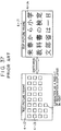
- FIG. 37 is a diagram illustrating a conventional technique.
- a monitor picture surface 4-J1 of a personal computer comprising 640 x 400 dots.
- a picture frame 4-J2 displays a text or an image.
- Reference numeral 4-J3 represents a recognized (or misrecognized) character displayed in a font of the personal computer, and is schematically represented by ⁇ in the present example.
- a bit image 4-J4 represents a character image of the original document image. In the present example, switching between the text picture frame and the image picture frame is performed-using a switch, such as a function key or the like.
- a scrolling bar (not shown) may be assigned by a pointing device, or a picture-frame scrolling key allocated on a keyboard may be depressed.
- characters as a result of recognition are diaplayed in a font comprising 16 x 16 dots to constitute a text, and editing operations, such as insertion, deletion, replacement or the like, can be performed.
- the text picture frame can be scrolled in the same manner as the image picture frame.
- an area where the image data can be displayed is limited, and it is therefore troublesome to display a desired portion of the text data in the limited area. Hence, it is in some cases easier to see the original document.
- one line of each of the text and image picture frames is displayed so that an image on the corresponding line of the text is shown above the text.
- This approach still has the inconvenience of having to perform a scrolling operation in the lateral direction.
- a text must be corrected while seeing not only the concerned line but also the entire sentence. If, for example, substantially the same character string appears in two or more portions, correction for such portions is inconvenient in this approach.
- step S3-501 an image-bearing original is read from a scanner, and an analog electrical signal is obtained.
- step S3-502 the signal is subjected to binary-coding processing to be converted into binary digital data (hereinafter termed an image).
- step S3-503 an image-window picture frame for displaying an image on a display provided in the apparatus is opened, and the image is displayed as shown in FIG. 41.
- a plurality of window picture frames can be simultaneously displayed on the display.
- an image window 4-101 is displayed on the entire picture surface of the display.
- step S3-504 the operator of the apparatus assigns an area to be recognized (hereinafter termed a recognition area), for example, an area indicated by reference numeral 4-102 in FIG. 41, by a pointing device, such as a mouse or the like, while watching the image displayed on the display.
- a recognition area for example, an area indicated by reference numeral 4-102 in FIG. 41
- a pointing device such as a mouse or the like
- step S3-505 a result window for displaying a result of recognition of a character image contained in the recognition area is opened.
- step S3-506 character segmenting processing for individually taking out characters in the character image within the assigned recognition area is executed.
- step S3-507 recognition processing is executed for respective images of the segmented characters.
- step S3-508 the result of recognition is displayed on the result window.
- result windows 4-104 having various sizes shown in FIGS. 44 through 46, and the results of recognition displayed on such result windows 4-104.
- the results of recognition shown in FIGS. 44 through 46 are obtained from the character image contained in the recognition area 4-102 assigned from the image displayed on the image window 4-101 shown in FIG. 41.
- reference numeral 4-104 represents a result window
- a reference numeral 4-105 represents a mode setting window for setting various kinds of modes necessary for recognition operations.
- the present invention has been made in consideration of the above-described problems in the prior art.
- the present invention by displaying both text and image data so as to correspond with each other, and switching a display picture frame so as to display the corresponding portion of the other data in accordance with scrolling of one data or an instruction for a part of one data, it is always possible to see the text and image data so as to correspond with each other without expressly giving instructions to two kinds of picture frames for the text and image data.
- the image data can be displayed in a desired size in accordance with the size of the original and the object of an operation.
- a window for displaying the result of character recognition is opened after determining its size in accordance with the number of characters contained within a region to be subjected to character recognition, it is always possible to obtain a window having an appropriate size for the result of character recognition. Accordingly, the size of the window does not become so large as to produce an unnecessary portion on the picture frame nor so small as to cause difficulty in seeing the result of character recognition. Hence, the result of recognition can be easily confirmed and corrected.
- FIG. 1 is a block diagram showing the schematic configuration of a character recognition apparatus according to a first embodiment of the present invention:
- a character recognition apparatus 1 of the first embodiment In FIG. 1, there is shown a character recognition apparatus 1 of the first embodiment.
- An input unit 2 reads and inputs a document image, comprising a scanner or the like, and inputs original image data as, for example, binary digital data.
- a ROM (read-only memory) 4 stores control programs of processing of flowcharts shown in figures after FIG. 13 and various kinds of data to be executed by the CPU 3.
- a RAM (random access memory) 5 is used as work areas for the CPU 3, and also includes an area for storing document image data input from the input unit 2, and an area for storing the positions and sizes of character patterns segmented from the input document image data by a preprocessing unit 7.
- a corresponding-image display unit 6 rewrites an image displayed on an image display unit 14 in accordance with the position and size of a character pattern corresponding to a character selected by a recognition-result display unit 15.
- the preprocessing unit 7 segments the pattern of a single character in the document image stored in the RAM 5, and executes various kinds of normalising operations.
- a recognition unit 8 extracts geometrical characteristics from the pattern preprocessed by the preprocessing unit 7, and performs character recognition of the document image by collating the extracted characteristics with a standard pattern stored in a dictionary 9 for recognition.
- a display unit 10 comprises an image display unit 14 for displaying an input document image, and a recognition-result display unit 15, and controls the display of the apparatus. The result of recognition can be corrected by the control of the recognition-result display unit 15 while watching the display.
- a system bus 11 includes a data bus from the CPU 3, an address bus, a control-signal bus and the like.
- An interface unit 12 controls interface with an external output device, such as a printer 13 or the like.
- FIG. 2 shows an example of the document image input to the character recognition apparatus 1 of the present embodiment.
- a document image 21 to be read by the input unit 2.
- the user instructs recognition for a portion 22 within the document image 21.
- Reference numeral 23 represents a portion displayed on an image window shown in FIG. 3.
- Reference numeral 24 represents a portion displayed on an image window shown in FIG 5.
- FIGS. 3 through 12 shows an image window and a recognition-result window displayed on the picture surface of a personal computer or the like.
- the image window and the recognition-result window are displayed by the control of the image display unit 14 and the recongition-result display unit 15, respectively.
- FIG. 3 shows an image window and a recognition-result window after executing recognition.
- an image window 31 a recognition-result window 32
- each button 33 for scrolling the portion displayed on the corresponding window
- each button 34 for indicating an approximate position of the portion displayed on the corresponding window with respect to the entire image.
- Reference numeral 35 represents a character selected by a character selection means. The character is selected by the movement of a cursor and the instruction of character selection by the character selection means.
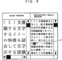
- FIG. 4 is a diagram indicating that a character is selected by the character selection means.
- Reference numeral 41 represents the character selected by the character selection means.
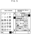
- FIG. 5 is a diagram showing that the image window is rewritten by the corresponding-image display unit 6 so that the image of the portion corresponding to the character can be seen after the character has been selected by the character selection means.
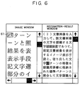
- FIGS. 6 - 8 are diagrams showing that the image window is rewritten by the corresponding-image display unit 6 so that the image of a portion corresponding to the character can be seen after the character has been selected by the character selection means, and the portion corresponding to the character is displayed.
- Reference numerals 61, 71 and 81 represent the portion corresponding to the character displayed in screen, in a frame, andin reversal, respectively.
- FIG. 9 shows the image window and the recognition-result window after executing recognition.
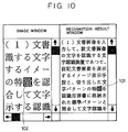
- FIG. 10 is a diagram showing that after selecting a character 101 by the character selection means, only a portion 102 corresponding to the character is displayed in reversal without rewriting the image, since the image containing the portion corresponding to the character is already displayed.
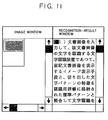
- FIG. 11 shows the image window and the recognition-result window after recognition.
- the image window the document image is displayed in a reduced size so that the entire image can be seen.
- FIG. 12 is a diagram showing that after selecting the character by the character selection means, the image window is displayed in a magnified size so that the portion corresponding to the character can be easily seen.
- FIG. 13 is a flowchart illustrating the operation of the CPU 3 in the first embodiment.
- the control program for executing this processing is stored in the ROM 4.
- step S131 the document image 21 set by the operator is read and input by the input unit (scanner) 2, and is stored in the memory 5.
- step S132 preprocessing is performed by the preprocessing unit 7, and character recognition is performed by the recognition unit 8.
- the results are stored in the memory 5.
- step S133 where the result of the recognition is displayed by the image display unit 14 of the display unit 10.
- the result of the recognition is displayed on the recognition-result window 32.
- the document image 21 is displayed on the image window 31 so that the upper left portion of the recognized portion 22 can be seen (default).
- step S134 the document image 21 is redisplayed by the corresponding-image display unit 6 so that the image portion corresponding to the character 41 selected by the character selection means can be seen. This corresponds to the image displayed on the image window shown in FIG. 5.
- FIG. 14 is a flowchart showing the processing of displaying the corresponding image in step S134 shown in FIG. 13.
- step S141 the position and the size of the character 41 selected by the character selection means are found out from the memory 5. Subsequently, in step S142, the image is redisplayed so that the corresponding portion is positioned at the upper left portion of the image window (see FIG. 5).
- the first embodiment it is possible to provide a character recognition apparatus which is easy to use for the user, since an original image of a portion to be corrected by the user can be automatically displayed.
- FIG. 15 is a flowchart showing processing when the corresponding image is displayed in step S134 shown in FIG. 13.
- step S151 the corresponding portion is displayed in screen 61, as shown in FIG. 6. That is, in addition to the above-described processing, the image portion of the character selected by the character selection means is clearly shown.
- step S161 determination (step S161) whether the corresponding portion is already displayed on the image window is inserted between steps S141 and S142 shown in the flowchart of FIG. 14. If the corresponding portion is displayed as shown in FIG. 9 and is therefore determined to be already displayed on the image window in step S161, only reversal display of the corresponding portion is performed in step S151 (see FIG. 10). If the result of determination in step S161 is negative, the image is redisplayed so that the corresponding portion is positioned at the upper left of the image window in step S142, in the same manner as in the flowchart of FIG. 15. Subsequently, in step S151, the corresponding portion is displayed in screen.
- magnification/reduction of the displayed image (step S171) to a size easy to see is performed between steps S141 and S142 shown in the flowchart of FIG. 14.
- step S141 the position and the size of the character selected by the character selection means are found out from the memory 5.
- step S171 the displayed image is magnified or reduced to a size easy to see.
- the instruction of magnification/reduction is performed through a keyboard or a mouse. This operation is performed because usually, after reading an image by the input unit 2, the entire document image is in many cases displayed in a reduced size and an area to be recognised is assigned, and therefore the image is too small to see if the corresponding portion is displayed on the image window.
- step S142 the image is redisplayed so that the corresponding portion is positioned at the upper left of the image window.
- step S151 the corresponding portion is displayed in reversal.
- the present embodiment it becomes possible to automatically display the original image of the portion to be corrected by the user.
- the user need not perform correction by directly referring to the original document or by finding out the corresponding portion in the original image.
- the apparatus of the embodiment is easy to use, and the operability in character recognition is improved.
- Means for setting various kinds of functions explained with reference to FIGS. 6 - 12 to initial states as defaults and instructing switching between the functions may, of course, be provided so that desired processing can be performed according to the instruction.
- FIG. 18 is a block diagram showing the configuration of a character recognition apparatus according to a second embodiment of the present invention.
- a CPU 2-1 for executing processing procedures of the present embodiment
- a bus 2-2 for a CRT (cathode-ray tube) 2-3 for displaying texts and images
- a video interface 2-4 between the CPU 2-1 and the CRT 2-3
- a VRAM 2-5 for storing texts and images to be displayed on the CRT 2-3
- an image scanner 2-6 for inputting images
- a scanner interface 2-7 for a pointing device 2-8 for assigning coordinates on the CRT 2-3
- an interface 2-9 for the pointing device 2-8
- a program memory 2-10 for storing processing procedures of the CPU 2-1
- a work RAM 2-11 for storing operational areas, document images and the like for the processing procedures
- a recognition unit 2-12 for recognising characters.
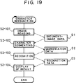
- FIG. 19 is a flowchart showing processes of character recognition.
- FIG. 20 is a flowchart showing processes of ganged movement of images. These processing procedures are stored in the program memory 2-10, and are executed by the CPU 2-1. The processes will now be explained in the sequence thereof.
- step S2-101 the document is read by the image scanner 2-6, and binary-coded document image data (an image) D1 are stored in the work RAM 2-11.
- step S2-102 segmenting of characters is performed by processing the document image data D1. That is, projection in the lateral direction (the x-axis direction) is first performed, and segmenting of character lines is performed by dividing the projected images at spacings between the images. Subsequently, projection in the vertical direction (the y-axis direction) is performed for each line, and segmenting of characters is performed by dividing the projected images at spacings between the images.
- the image of each character can be segmented with its circumscribed rectangle, whereby the divided images of individual characters can be obtained.
- the coordinates of the upper left point of the circumscribed rectangle of each character (the x-y coordinates when the upper left portion of the original document image is made to be the origin, termed a character position) can also be obtained.
- the segmented character image and the position of the character are stored in the work RAM 11 as segmentation data D2.
- FIG. 22 is a diagram schematically showing the relationship between the above-described segmented character image and the position of the character.
- the position of the character is represented by (400, 800) as data in units of a dot making the upper left portion of the original document image to be the origin.
- This data represents the output position of a dot, and may be represented, for example, in 1/128 of the above-described value, provided that a correspondence is present between the represented value and the actual position.
- the position of the character and the character image are stored in the work RAM 2-11 as the segmentation data D2.
- the segmentation data D2 and and recognition data D3 are stored in the work RAM 2-11 so as to correspond to each other.
- step S2-103 the character image is transmitted to the recognition unit 2-12, which recognizes what character the transmitted image represents, and stores a character code as a result of the recognition in the work RAM 2-11 as recognition data D3.
- a known method such as a directional-index histogram method or the like, is used as the algorithm for recognition. However, the choice of algorithm is not limited to such a method.
- the recognition data is displayed on the text picture frame of the CRT 2-3, as shown in FIG. 21.
- the position of the character displayed on the text picture frame is made to correspond to the address of the corresponding recognition data.
- the position of the character on the text picture frame can correspond to the position of the character in the original image (coordinates conversion means).
- the picture surface of the CRT 2-3 is divided into the left half portion and the right half portion as the text picture frame and the image picture frame, respectively.
- the document image is displayed on the image picture frame so that the upper left portion of the document is positioned at the upper left portion of the image when the image has been read.
- step S2-201 the apparatus is in a WAIT state (step S2-201, where an input of coordinates is awaited.
- the character in the text picture frame shown in FIG. 21 is assigned by the pointing device 2-8.
- pointing device interrupt is generated to terminate the WAIT state.
- step S2-202 the assigned coordinates are read. If the coordinates have not assigned a character (the determination in step S2-203), the process returns to step S2-201 to resume a WAIT state. If the coordinates have assigned a character, the process proceeds to step S2-204. In step S2-204, to which recognition data D3 the assigned character corresponds is determined while searching the data D3 in the upstream direction.
- step S2-205 the image is redisplayed based on the new coordinates of the origin for image display.
- a state in which the original image corresponding to the character in the text picture frame is not displayed is replaced by a state in which the original image containing the character is situated at the upper left of the image picture frame.
- step S2-206 editing processing, such as insertion, deletion, replacement or the like, is performed for the assigned character on the text picture frame.
- processing such as movement or the like, may be performed for the corresponding image picture frame as an image-data block, and processing, such as insertion or the like, may be performed using the character-pattern image on the text picture frame.
- the present invention may, of course, be achieved in an apparatus or a system, or by supplying a program to the apparatus or the system.
- the corresponding portion is not limited to be positioned at the upper left of the picture frame, but may be positioned at the center of the picture frame, or at any other arbitrary position.
- Processing data formed from the original image is not limited to character recognition, but may be any data which can correspond to the image.
- FIG. 23 is a block diagram showing the configuration of an optical character reader (OCR) according to a third embodiment of the present invention.
- OCR optical character reader
- a scanner 3-1 projects light onto an image-bearing original, read light reflected by the original, and outputs an analog electrical signal.
- a binary-coding circuit 3-2 performs digital conversion of the electrical signal output from the scanner 3-1 into a binary signal corresponding to the black-and-white image of the original.
- a mouse 3-3 functions as a pointing device for inputting coordinates for, for example, area assignment on an image window.
- a mouse interface circuit 3-4 transmits the signal from the mouse 3-3 to other components consitutiting the apparatus.
- a CPU 3-5 controls the entire apparatus and executes character segmenting processing, recognition processing and the like.
- a ROM 3-6 stores control programs and various kinds of processing programs to be executed by the CPU 3-5, a dictionary for recognition and the like.
- a RAM 3-7 is used, for example, as work areas for the development of character images and character recognition processing.
- a display 3-8 displays input images and recognition results. There are also shown a display interface circuit 3-9, and a CPU bus 3-10 for connecting respective components of the apparatus.
- steps S3-501 - S3-504 input of an image-bearing original, binary-coding processing, image display, and assignment of a recognition area by the mouse are performed according to the conventional technique.
- step S3-10 character segmenting processing is performed from the assigned recognition area, and rectangular areas corresponding to respective characters are taken out.
- step S3-15 the maximum number of characters and the number of lines in the recognition area are calculated according to the result of the character segmenting processing.
- the size of the result window necessary for displaying characters as the result of recognition and not having unnecessary space is determined from the above-described values.
- step S3-20 the result window having the determined size is opened.
- steps S3-507 - S3-508 recognition processing is performed according to the conventional technique, and the result of the recognition is displayed on the result window.
- a display having an appropriate relationship between the size of the result-window and the amount of displayed characters as the result of the character recognition can be obtained, as shown in FIG. 25.
- reference numeral 3-11 represents the image window
- reference numeral 3-13 represents the result window
- reference numeral 3-14 represents a mode-setting window for setting various kinds of modes necessary for the operation of the OCR.
- Characters displayed on the result window 3-13 are obtained from the character image contained in the recognition area 4-102 assigned from the image displayed on the image window 4-101 shown in FIG. 41.
- the multiwindow picture surface comprises an overlap-type multiwindow in which respective windows overlap with one another
- a tile-type multiwindow in which windows do not overlap may, of course, be used, as shown in FIG. 26.
- reference numeral 3-15 represents a window for setting various kinds of processing modes
- reference numeral 3-16 represents an image window
- reference numeral 3-17 represents a result window.
- the height of the result window is fixed, while its width is determined in accordance with the maximum number of characters within the recognition area.
- Operations such as movement, resizing (magnification, reduction or the like), placement in front of another window, placement behind another window, and the like, may, of course, be freely performed for each window by operating the mouse.
- the size of the result window is determined in accordance with the maximum number of characters and the number of lines contained in the assigned recognition area, it is possible to obtain a result window which is appropriate for the amount of displayed characters as the result of character recognition, and therefore to perform appropriate display which provides no difficulty in seeing the displayed sentence.
- steps S3-501 - S3-503 input of an image-bearing original, binary-coding processing and image display are performed according to the conventional technique.
- step S3-30 the recognition area is assigned using the mouse 3-3.
- line segments are drawn on the image-window picture frame by operating the mouse 3-3, a polygon is formed by connecting the line segments, and an area surrounded by the polygon is considered to be the recognition area.
- the operations of assigning the recognition area will be specifically explained with reference to display picture surfaces illustrated in FIGS. 28 - 30.
- FIG. 28 is a diagram showing a state in which the image-bearing original input from the scanner 1 is displayed on the image window 3-41 after the completion of the processing of step S3-503.
- line segments 3-42 and 3-43 are already written, indicating that a polygon for assigning the recognition area is in the course of being drawn.
- the assignment of line segments is performed through the mouse 3-3. By performing a single clicking operation of the button of the mouse 3-3 after moving a cursor 3-40 to a desired position, the start point or the end point of a line segment costituting the polygon is determined.
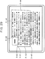
- FIG. 29 shows a state in which the drawing operation of the polygon is further advanced from the state shown in FIG. 28, and the final line segment is to be determined.
- line segments 3-44, 3-45 and 3-46 have been drawn by continuing respective single clicking operations of the button of the mouse 3-3 while moving the cursor 3-40 to desired positions.
- the button of the mouse 3-3 is clicked twice (double clicking) after moving the cursor 3-40 to the desired position.
- the position of the cursor 3-40 is connected to the start point 3-51 where the formation of the polygon has been started with a straight line to complete the polygon 3-61 shown in FIG. 30.
- This polygon 3-61 is considered as the recognition area.
- step S3-35 character segmenting processing within the assigned area is executed, and rectangular areas for respective characters are taken out.
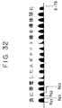
- This processing will be more specifically explained with reference to FIGS. 31 and 32.
- character segmenting processing is performed using a histogram of black picture elements obtained by projection in the present embodiment. Any other segmenting method, such as contour-line tracking or the like, may, of course, be used.
- the assigned recognition area is a rectangular area 3-71 shown in FIG. 31. If an x-y coordinate system comprising the x-axis in the lateral direction and the y-axis in the vertical direction as shown in FIG. 31 is considered, coordinates within this rectangular area can be expressed by a0 ⁇ x ⁇ a1, and b0 ⁇ y ⁇ b1.
- a histogram 3-72 in the direction of the y-axis is obtained.
- the values of the y-coordinates of the start points and the end points of respective lines are calculated as Y S1 , Y E1 , Y S2 , Y E2 , ... according to the histogram 3-72.
- steps S3-507 and S3-508 recognition processing for the segmented character image is performed according to the conventional technique, and the result of the recognition is displayed on the result window.
- a polygon obtained by freely combining a plurality of line segments becomes the recognition area, it is possible to assign a recognition area having a complicated outer shape which cannot be assigned by a mouse in a simple manner. According to such an approach, even if a photograph, a drawing, a heading or the like is present, it is possible to select a recognition area with easily removing the unnecessary photograph or the like.
- a mouse is used as the pointing device
- any other kind of pointing device may also be used.
- an explanation has been provided of a case in which a single clicking operation and a double clicking operation of a mouse button is used for defining a line segment and a polygon, respectively, when the polygon is formed, these clicking operations may be changed, or a line segment or a polygon may be defined when the mouse button is released.
- the area 4-103 shown in FIG. 42 explained in the conventional approach is considered as the area to be recognized.
- a rectangular area 3-81 shown in FIG. 34 is assigned by the mouse 3-3.
- the rectangular area 3-81 is defined by first clicking the mouse button while adjusting the mouse cursor to the upper left end of the rectangular area 3-81, and clicking again the mouse button after moving the mouse to the lower right end of the rectangular area 3-81.
- a rectangular area 3-82 is assigned by operating the mouse 3-3 in the same manner as described above.
- a polygon is formed by continuously assigning a plurality of rectangular areas by the mouse and synthesising the assigned rectangular areas. For example, in the case of FIG.
- the synthesis of rectangular areas resides in leaving only the outermost portions of line segments constituting assigned rectangles. Such synthesis processing is performed every time a rectangular area having an overlapped portion is assigned, and only the outermost line segments always remain as border lines of the recognition area.
- the present invention may be applied to a system comprising a plurality of apparatuses, or to an apparatus comprising a single unit.
- the present invention may, of course, be applied to a case in which the object of the invention is achieved by supplying a system or an apparatus with programs.
Landscapes
- Engineering & Computer Science (AREA)
- Theoretical Computer Science (AREA)
- Physics & Mathematics (AREA)
- General Physics & Mathematics (AREA)
- General Engineering & Computer Science (AREA)
- Multimedia (AREA)
- Computer Vision & Pattern Recognition (AREA)
- Health & Medical Sciences (AREA)
- Artificial Intelligence (AREA)
- Audiology, Speech & Language Pathology (AREA)
- Computational Linguistics (AREA)
- General Health & Medical Sciences (AREA)
- Human Computer Interaction (AREA)
- Character Input (AREA)
- Character Discrimination (AREA)
Applications Claiming Priority (9)
| Application Number | Priority Date | Filing Date | Title |
|---|---|---|---|
| JP3218571A JPH0581467A (ja) | 1991-08-29 | 1991-08-29 | 画像処理方法及び装置 |
| JP21857191 | 1991-08-29 | ||
| JP218571/91 | 1991-08-29 | ||
| JP272706/91 | 1991-10-21 | ||
| JP3272706A JPH05108792A (ja) | 1991-10-21 | 1991-10-21 | 画像処理方法及び装置 |
| JP27270691 | 1991-10-21 | ||
| JP3288274A JPH05128302A (ja) | 1991-11-05 | 1991-11-05 | 文字認識方法及びその装置 |
| JP28827491 | 1991-11-05 | ||
| JP288274/91 | 1991-11-05 |
Publications (3)
| Publication Number | Publication Date |
|---|---|
| EP0531060A2 true EP0531060A2 (fr) | 1993-03-10 |
| EP0531060A3 EP0531060A3 (en) | 1993-07-21 |
| EP0531060B1 EP0531060B1 (fr) | 1999-12-08 |
Family
ID=27330159
Family Applications (1)
| Application Number | Title | Priority Date | Filing Date |
|---|---|---|---|
| EP92307847A Expired - Lifetime EP0531060B1 (fr) | 1991-08-29 | 1992-08-28 | Procédé et appareil de traitement d'image |
Country Status (3)
| Country | Link |
|---|---|
| US (1) | US5703962A (fr) |
| EP (1) | EP0531060B1 (fr) |
| DE (1) | DE69230392T2 (fr) |
Cited By (4)
| Publication number | Priority date | Publication date | Assignee | Title |
|---|---|---|---|---|
| EP0629958A3 (fr) * | 1993-06-02 | 1995-08-02 | Canon Kk | Méthode et dispositif de traitement d'un document. |
| EP1122632A1 (fr) * | 2000-02-04 | 2001-08-08 | Bernd J. Hobrack | Procédé et système de traitement de données pour la coordination d'applications d'un logiciel d'ordinateur |
| CN1106620C (zh) * | 1994-06-16 | 2003-04-23 | 佳能株式会社 | 信息处理方法和设备 |
| US12420187B2 (en) | 2021-05-14 | 2025-09-23 | Tencent Technology (Shenzhen) Company Limited | Information display method and apparatus, terminal, storage medium, and computer program product |
Families Citing this family (16)
| Publication number | Priority date | Publication date | Assignee | Title |
|---|---|---|---|---|
| EP0587450B1 (fr) | 1992-09-11 | 2004-11-17 | Canon Kabushiki Kaisha | Méthode et appareil de traitement d'image |
| US5892843A (en) * | 1997-01-21 | 1999-04-06 | Matsushita Electric Industrial Co., Ltd. | Title, caption and photo extraction from scanned document images |
| US6052663A (en) * | 1997-06-27 | 2000-04-18 | Kurzweil Educational Systems, Inc. | Reading system which reads aloud from an image representation of a document |
| US6298173B1 (en) | 1997-10-03 | 2001-10-02 | Matsushita Electric Corporation Of America | Storage management system for document image database |
| US6327388B1 (en) | 1998-08-14 | 2001-12-04 | Matsushita Electric Industrial Co., Ltd. | Identification of logos from document images |
| JP2001184453A (ja) * | 1999-12-22 | 2001-07-06 | Hitachi Ltd | 帳票処理システムおよび帳票ファイリングシステム |
| JP2002024762A (ja) * | 2000-06-30 | 2002-01-25 | Toshiba Corp | 文書認識装置及びその方法 |
| US7102767B2 (en) | 2002-07-19 | 2006-09-05 | Kabushiki Kaisha Toshiba | Print module for direct multiple image formatting and printing |
| US20090169110A1 (en) * | 2005-04-20 | 2009-07-02 | Hiroaki Masuyama | Index term extraction device and document characteristic analysis device for document to be surveyed |
| US7471826B1 (en) | 2008-03-31 | 2008-12-30 | International Business Machines Corporation | Character segmentation by slices |
| US10607381B2 (en) * | 2014-07-07 | 2020-03-31 | Canon Kabushiki Kaisha | Information processing apparatus |
| JP6794284B2 (ja) * | 2017-01-31 | 2020-12-02 | キヤノン株式会社 | カメラ機能を有する携帯可能な情報処理装置、その表示制御方法、及びプログラム |
| JP6938318B2 (ja) | 2017-10-03 | 2021-09-22 | キヤノン株式会社 | 情報処理装置、情報処理方法及びプログラム |
| JP6784274B2 (ja) * | 2018-04-02 | 2020-11-11 | 日本電気株式会社 | 画像処理装置、画像処理方法およびプログラム |
| CN111563497B (zh) * | 2020-04-30 | 2024-04-16 | 广东小天才科技有限公司 | 基于移动轨迹的框题方法、装置、电子设备及存储介质 |
| CN113936281A (zh) * | 2021-10-12 | 2022-01-14 | 北京百度网讯科技有限公司 | 一种文档扫描方法、装置、电子设备和存储介质 |
Family Cites Families (10)
| Publication number | Priority date | Publication date | Assignee | Title |
|---|---|---|---|---|
| DE3138757A1 (de) * | 1981-09-29 | 1983-05-05 | Siemens AG, 1000 Berlin und 8000 München | Verfahren zur erfassung von textausschnitten aus einer vorlage und vorrichtung zur durchfuehrung des verfahrens |
| US4761818A (en) * | 1983-04-08 | 1988-08-02 | Canon Kabushiki Kaisha | Image processing apparatus |
| JPH07107694B2 (ja) * | 1984-08-31 | 1995-11-15 | 株式会社日立製作所 | 文書処理装置 |
| JPS61253587A (ja) * | 1985-05-02 | 1986-11-11 | Mitsubishi Electric Corp | 光学文字読取装置 |
| JPS63109591A (ja) * | 1986-10-27 | 1988-05-14 | Sharp Corp | 光学的文字読取装置 |
| US4965678A (en) * | 1987-03-03 | 1990-10-23 | Canon Kabushiki Kaisha | Area designation apparatus in image processing system |
| JP2553608B2 (ja) * | 1988-01-04 | 1996-11-13 | 住友電気工業 株式会社 | 光学文字読取装置 |
| JPH02201588A (ja) * | 1989-01-31 | 1990-08-09 | Toshiba Corp | 文字読取装置 |
| JPH0816918B2 (ja) * | 1989-04-18 | 1996-02-21 | シャープ株式会社 | 行抽出方法 |
| US5048099A (en) * | 1990-05-21 | 1991-09-10 | Eastman Kodak Company | Polygon-based method for automatic extraction of selected text in a digitized document |
-
1992
- 1992-08-25 US US07/934,313 patent/US5703962A/en not_active Expired - Lifetime
- 1992-08-28 DE DE69230392T patent/DE69230392T2/de not_active Expired - Fee Related
- 1992-08-28 EP EP92307847A patent/EP0531060B1/fr not_active Expired - Lifetime
Cited By (6)
| Publication number | Priority date | Publication date | Assignee | Title |
|---|---|---|---|---|
| EP0629958A3 (fr) * | 1993-06-02 | 1995-08-02 | Canon Kk | Méthode et dispositif de traitement d'un document. |
| US5751849A (en) * | 1993-06-02 | 1998-05-12 | Canon Kabushiki Kaisha | Method and apparatus for processing a document |
| CN1106620C (zh) * | 1994-06-16 | 2003-04-23 | 佳能株式会社 | 信息处理方法和设备 |
| EP1122632A1 (fr) * | 2000-02-04 | 2001-08-08 | Bernd J. Hobrack | Procédé et système de traitement de données pour la coordination d'applications d'un logiciel d'ordinateur |
| WO2001056351A3 (fr) * | 2000-02-04 | 2002-03-21 | Bernd J Hobrack | Procede et systeme de traitement de donnees pour coordonner des applications d'un logiciel d'ordinateur |
| US12420187B2 (en) | 2021-05-14 | 2025-09-23 | Tencent Technology (Shenzhen) Company Limited | Information display method and apparatus, terminal, storage medium, and computer program product |
Also Published As
| Publication number | Publication date |
|---|---|
| DE69230392T2 (de) | 2000-05-11 |
| DE69230392D1 (de) | 2000-01-13 |
| US5703962A (en) | 1997-12-30 |
| EP0531060B1 (fr) | 1999-12-08 |
| EP0531060A3 (en) | 1993-07-21 |
Similar Documents
| Publication | Publication Date | Title |
|---|---|---|
| US5703962A (en) | Image processing method and apparatus | |
| US6466694B2 (en) | Document image processing device and method thereof | |
| US8780117B2 (en) | Display control apparatus and display control method capable of rearranging changed objects | |
| JP2536966B2 (ja) | テキスト編集システム | |
| US6230169B1 (en) | Apparatus with a display magnification changing function of annotation | |
| US8682642B2 (en) | Translation display apparatus | |
| US5933843A (en) | Document processing apparatus displaying and processing a plurality of successive contiguous pages of the same document in overlapping windows | |
| US5509092A (en) | Method and apparatus for generating information on recognized characters | |
| EP1361544A2 (fr) | Système et procédé d'édition d'images électroniques | |
| US7009612B2 (en) | Apparatus and method for font generation, and computer-readable storage medium recording program for the same | |
| JP2001175807A (ja) | テキスト領域選択方法 | |
| JPH08212197A (ja) | 文書編集装置 | |
| US6810147B2 (en) | Document image processing apparatus for processing line portions manually input to document image, method therefor, and computer readable recording medium recorded with document image processing program therefor | |
| JP3319203B2 (ja) | 文書ファイリング方法及び装置 | |
| US5727224A (en) | Document image processor for inserting and editing bracket symbols and associated text | |
| JPH10312407A (ja) | 図面表示装置 | |
| US6275609B1 (en) | Image processing apparatus and method | |
| JPH103516A (ja) | 情報処理方法及び装置 | |
| JP4297815B2 (ja) | 情報処理装置および処理方法およびプログラムおよび記録媒体 | |
| JPH05128302A (ja) | 文字認識方法及びその装置 | |
| JP2858581B2 (ja) | 画像処理方法及び装置 | |
| JP3717971B2 (ja) | 認識文字とイメージデータの対応的表示方法及び文字認識装置 | |
| US20050108635A1 (en) | Document processing apparatus and storage medium | |
| JPH05108792A (ja) | 画像処理方法及び装置 | |
| JPH0581467A (ja) | 画像処理方法及び装置 |
Legal Events
| Date | Code | Title | Description |
|---|---|---|---|
| PUAI | Public reference made under article 153(3) epc to a published international application that has entered the european phase |
Free format text: ORIGINAL CODE: 0009012 |
|
| AK | Designated contracting states |
Kind code of ref document: A2 Designated state(s): DE FR GB |
|
| PUAL | Search report despatched |
Free format text: ORIGINAL CODE: 0009013 |
|
| AK | Designated contracting states |
Kind code of ref document: A3 Designated state(s): DE FR GB |
|
| 17P | Request for examination filed |
Effective date: 19931208 |
|
| 17Q | First examination report despatched |
Effective date: 19970530 |
|
| GRAG | Despatch of communication of intention to grant |
Free format text: ORIGINAL CODE: EPIDOS AGRA |
|
| GRAG | Despatch of communication of intention to grant |
Free format text: ORIGINAL CODE: EPIDOS AGRA |
|
| GRAH | Despatch of communication of intention to grant a patent |
Free format text: ORIGINAL CODE: EPIDOS IGRA |
|
| GRAH | Despatch of communication of intention to grant a patent |
Free format text: ORIGINAL CODE: EPIDOS IGRA |
|
| GRAA | (expected) grant |
Free format text: ORIGINAL CODE: 0009210 |
|
| AK | Designated contracting states |
Kind code of ref document: B1 Designated state(s): DE FR GB |
|
| REF | Corresponds to: |
Ref document number: 69230392 Country of ref document: DE Date of ref document: 20000113 |
|
| ET | Fr: translation filed | ||
| PLBE | No opposition filed within time limit |
Free format text: ORIGINAL CODE: 0009261 |
|
| STAA | Information on the status of an ep patent application or granted ep patent |
Free format text: STATUS: NO OPPOSITION FILED WITHIN TIME LIMIT |
|
| 26N | No opposition filed | ||
| REG | Reference to a national code |
Ref country code: GB Ref legal event code: IF02 |
|
| PGFP | Annual fee paid to national office [announced via postgrant information from national office to epo] |
Ref country code: GB Payment date: 20040816 Year of fee payment: 13 |
|
| PGFP | Annual fee paid to national office [announced via postgrant information from national office to epo] |
Ref country code: FR Payment date: 20040827 Year of fee payment: 13 |
|
| PGFP | Annual fee paid to national office [announced via postgrant information from national office to epo] |
Ref country code: DE Payment date: 20041028 Year of fee payment: 13 |
|
| PG25 | Lapsed in a contracting state [announced via postgrant information from national office to epo] |
Ref country code: GB Free format text: LAPSE BECAUSE OF NON-PAYMENT OF DUE FEES Effective date: 20050828 |
|
| PG25 | Lapsed in a contracting state [announced via postgrant information from national office to epo] |
Ref country code: DE Free format text: LAPSE BECAUSE OF NON-PAYMENT OF DUE FEES Effective date: 20060301 |
|
| GBPC | Gb: european patent ceased through non-payment of renewal fee |
Effective date: 20050828 |
|
| PG25 | Lapsed in a contracting state [announced via postgrant information from national office to epo] |
Ref country code: FR Free format text: LAPSE BECAUSE OF NON-PAYMENT OF DUE FEES Effective date: 20060428 |
|
| REG | Reference to a national code |
Ref country code: FR Ref legal event code: ST Effective date: 20060428 |