EP0533419A1 - Système de commande d'embrayage à verrouillage pour une transmission automatique de véhicule - Google Patents
Système de commande d'embrayage à verrouillage pour une transmission automatique de véhicule Download PDFInfo
- Publication number
- EP0533419A1 EP0533419A1 EP92308340A EP92308340A EP0533419A1 EP 0533419 A1 EP0533419 A1 EP 0533419A1 EP 92308340 A EP92308340 A EP 92308340A EP 92308340 A EP92308340 A EP 92308340A EP 0533419 A1 EP0533419 A1 EP 0533419A1
- Authority
- EP
- European Patent Office
- Prior art keywords
- speed ratio
- clutch
- lock
- fuzzy
- control
- Prior art date
- Legal status (The legal status is an assumption and is not a legal conclusion. Google has not performed a legal analysis and makes no representation as to the accuracy of the status listed.)
- Granted
Links
Images












Classifications
-
- F—MECHANICAL ENGINEERING; LIGHTING; HEATING; WEAPONS; BLASTING
- F16—ENGINEERING ELEMENTS AND UNITS; GENERAL MEASURES FOR PRODUCING AND MAINTAINING EFFECTIVE FUNCTIONING OF MACHINES OR INSTALLATIONS; THERMAL INSULATION IN GENERAL
- F16H—GEARING
- F16H61/00—Control functions within control units of change-speed- or reversing-gearings for conveying rotary motion ; Control of exclusively fluid gearing, friction gearing, gearings with endless flexible members or other particular types of gearing
- F16H61/14—Control of torque converter lock-up clutches
- F16H61/143—Control of torque converter lock-up clutches using electric control means
-
- B—PERFORMING OPERATIONS; TRANSPORTING
- B60—VEHICLES IN GENERAL
- B60W—CONJOINT CONTROL OF VEHICLE SUB-UNITS OF DIFFERENT TYPE OR DIFFERENT FUNCTION; CONTROL SYSTEMS SPECIALLY ADAPTED FOR HYBRID VEHICLES; ROAD VEHICLE DRIVE CONTROL SYSTEMS FOR PURPOSES NOT RELATED TO THE CONTROL OF A PARTICULAR SUB-UNIT
- B60W50/00—Details of control systems for road vehicle drive control not related to the control of a particular sub-unit, e.g. process diagnostic or vehicle driver interfaces
- B60W2050/0001—Details of the control system
- B60W2050/0043—Signal treatments, identification of variables or parameters, parameter estimation or state estimation
- B60W2050/0057—Frequency analysis, spectral techniques or transforms
-
- F—MECHANICAL ENGINEERING; LIGHTING; HEATING; WEAPONS; BLASTING
- F16—ENGINEERING ELEMENTS AND UNITS; GENERAL MEASURES FOR PRODUCING AND MAINTAINING EFFECTIVE FUNCTIONING OF MACHINES OR INSTALLATIONS; THERMAL INSULATION IN GENERAL
- F16H—GEARING
- F16H61/00—Control functions within control units of change-speed- or reversing-gearings for conveying rotary motion ; Control of exclusively fluid gearing, friction gearing, gearings with endless flexible members or other particular types of gearing
- F16H2061/0015—Transmission control for optimising fuel consumptions
-
- F—MECHANICAL ENGINEERING; LIGHTING; HEATING; WEAPONS; BLASTING
- F16—ENGINEERING ELEMENTS AND UNITS; GENERAL MEASURES FOR PRODUCING AND MAINTAINING EFFECTIVE FUNCTIONING OF MACHINES OR INSTALLATIONS; THERMAL INSULATION IN GENERAL
- F16H—GEARING
- F16H61/00—Control functions within control units of change-speed- or reversing-gearings for conveying rotary motion ; Control of exclusively fluid gearing, friction gearing, gearings with endless flexible members or other particular types of gearing
- F16H2061/0075—Control functions within control units of change-speed- or reversing-gearings for conveying rotary motion ; Control of exclusively fluid gearing, friction gearing, gearings with endless flexible members or other particular types of gearing characterised by a particular control method
- F16H2061/0081—Fuzzy logic
-
- F—MECHANICAL ENGINEERING; LIGHTING; HEATING; WEAPONS; BLASTING
- F16—ENGINEERING ELEMENTS AND UNITS; GENERAL MEASURES FOR PRODUCING AND MAINTAINING EFFECTIVE FUNCTIONING OF MACHINES OR INSTALLATIONS; THERMAL INSULATION IN GENERAL
- F16H—GEARING
- F16H61/00—Control functions within control units of change-speed- or reversing-gearings for conveying rotary motion ; Control of exclusively fluid gearing, friction gearing, gearings with endless flexible members or other particular types of gearing
- F16H61/14—Control of torque converter lock-up clutches
- F16H61/143—Control of torque converter lock-up clutches using electric control means
- F16H2061/145—Control of torque converter lock-up clutches using electric control means for controlling slip, e.g. approaching target slip value
-
- F—MECHANICAL ENGINEERING; LIGHTING; HEATING; WEAPONS; BLASTING
- F16—ENGINEERING ELEMENTS AND UNITS; GENERAL MEASURES FOR PRODUCING AND MAINTAINING EFFECTIVE FUNCTIONING OF MACHINES OR INSTALLATIONS; THERMAL INSULATION IN GENERAL
- F16H—GEARING
- F16H61/00—Control functions within control units of change-speed- or reversing-gearings for conveying rotary motion ; Control of exclusively fluid gearing, friction gearing, gearings with endless flexible members or other particular types of gearing
- F16H61/14—Control of torque converter lock-up clutches
-
- Y—GENERAL TAGGING OF NEW TECHNOLOGICAL DEVELOPMENTS; GENERAL TAGGING OF CROSS-SECTIONAL TECHNOLOGIES SPANNING OVER SEVERAL SECTIONS OF THE IPC; TECHNICAL SUBJECTS COVERED BY FORMER USPC CROSS-REFERENCE ART COLLECTIONS [XRACs] AND DIGESTS
- Y10—TECHNICAL SUBJECTS COVERED BY FORMER USPC
- Y10S—TECHNICAL SUBJECTS COVERED BY FORMER USPC CROSS-REFERENCE ART COLLECTIONS [XRACs] AND DIGESTS
- Y10S706/00—Data processing: artificial intelligence
- Y10S706/90—Fuzzy logic
Definitions
- This invention relates to an improved system for controlling the lock-up clutch of a torque converter of a vehicle automatic transmission system.
- the engagement range of the lock-up clutch is determined by retrieval from a two-dimensional shift diagram stored in a microcomputer memory as a map, hereinafter referred to as "shift diagram map", using the vehicle speed and the throttle opening as parameters.
- shift diagram map a map stored in a microcomputer memory
- the motive force reserve engine power
- this prior art control system only provides ON/OFF control between the engaged and disengaged states of the lock-up clutch in the third and fourth gears of the D range and does not provide control for semi-engaged clutch states, it does not take full advantage of the capability of the lock-up clutch to improve torque converter transmission efficiency while simultaneously using clutch semi-engagement to suppress the engine vibration that tends to become a problem during low speed driving.
- fuzzy reasoning that using fuzzy relationships and that using fuzzy production rules
- this prior art system controls clutch engagement/disengagement by fuzzy reasoning using fuzzy relationships.
- rules whose antecedents specify the conditions to be met for engagement/disengagement of the lock-up clutch, the degree of satisfaction of each control rule is determined and compared with that of the other rules, and the consequent of the rule whose antecedent has the greatest degree of satisfaction is selected for implementation.
- Reasoning by fuzzy relationships deals with a model expressed as complex relationships involving various fuzzy relationships connected in series and parallel.
- fuzzy reasoning is suitable for troubleshooting or diagnosis and other types of backward reasoning but is not appropriate for forward reasoning which, as in the case of decisions regarding lock-up, requires control values to be determined through the analysis of current phenomena.
- fuzzy reasoning by rules uses a model expressed on the control side in terms of "If ..., and then ...," permit human behaviour patterns to be easily expressed and the creation of a knowledge base to be facilitated.
- this mode of reasoning also makes it possible to formulate rules in the manner of a dialogue, it enables the control know-how acquired through the experience of an expert driver to be incorporated with increased accuracy so that control and response matched to human feelings can be more readily realized. Moreover, modifications in the control rules are easy to implement.
- the aforesaid prior art control determines the road grade through calculations without using a sensor. While this has the advantage of reducing the cost of the sensor system, it is disadvantageous in that the calculated value is only an estimate and is not necessarily adequate as regards reliability.
- An object of the invention is, therefore, to provide a system for controlling the lock-up clutch of a vehicle automatic transmission which overcomes the aforesaid shortcomings of the prior art and enables control that is better matched to the intention, decision-making, and feelings of a human driver.
- Another object of the invention is to provide a system for controlling the lock-up clutch of an automatic transmission which, like the prior art system, determines the driving resistance by processing operations without using a sensor but which ascertains the value thereof with markedly higher accuracy.
- a system for controlling the lock-up clutch of a torque converter of an automatic transmission of a vehicle which mechanically couples a pump impeller connected to an engine output shaft with a turbine runner connected to a transmission input shaft, comprising: first means for determining parameters indicative of operating conditions of the vehicle at least including the engine load, the driving resistance and the speed ratio of the torque converter; second means for carrying out a fuzzy reasoning to determine a target speed ratio; and third means for determining a control value in response to the determined target speed for controlling an actuator which controls the clutch such that the clutch may be controlled between the states in which the clutch is fully locked up and the clutch is fully not locked up including the state in which the clutch is partially locked up.
- the present invention comprises a system for controlling the lock-up clutch of a torque converter of an automatic transmission of a vehicle which mechanically couples a pump impeller connected to an engine output shaft with a turbine runner connected to a transmission input shaft, comprising first means for determining parameters indicative of operating conditions of the vehicle at least including the engine load, the driving resistance and the speed ratio of the torque converter, second means for carrying out a fuzzy reasoning to determine a target speed ratio based on fuzzy production rules each having an antecedent made up of a membership function defined with respect to at lest one of the parameters and a consequent made up of a membership function defined with respect to the target speed ratio and third means for determining a control value of an actuator in response to the determined target speed for controlling an actuator which controls the clutch such that the clutch may be controlled between the states in which the clutch is fully locked up and the clutch is fully not locked up including the state in which the clutch is partially locked up.
- the system of the present invention therefore achieves these objects by continuously controlling all states of the lock-up clutch between engagement and disengagement, including semi-engaged states, and by taking full advantage of the unique capabilities of the lock-up clutch through the use of control values obtained by fuzzy reasoning based on fuzzy production rules.
- FIG. 1 is a schematic diagram showing the overall arrangement of the system for controlling the lock-up clutch of a vehicle automatic transmission according to the present invention, in which the reference numeral 10 denotes the main unit of an internal combustion engine.
- the main engine unit 10 is connected with an air intake passage 12 having an air cleaner 14 attached to its far end.
- the flow rate of intake air supplied to the main engine unit 10 via the air cleaner 14 and the air intake passage 12 is controlled by a throttle valve 16 linked with and operated by means of an accelerator pedal (not shown) located on the vehicle floor in the vicinity of the driver's seat.
- a fuel injection valve (not shown) for supplying fuel to the engine is provided at an appropriate portion of the air intake passage 12 in the vicinity of the combustion chamber (not shown).
- the intake air mixed with the fuel enters the combustion chamber and, after being compressed by a piston (not shown), is ignited by a spark plug (not shown).
- the fuel-air mixture burns explosively and drives the piston.
- the motive force of the piston is converted into rotating motion which is made available at an engine output shaft 18.
- the stage following the main engine unit 10 is a transmission 20 comprising a torque converter 22 and a gear box 24 constituted of planetary gears and the like.
- the torque converter 22 comprises a pump impeller 22a, a turbine runner 22b, a cover (shell) 22c and a stator 22d.
- the pump impeller 22a is connected with the output shaft 18 via the cover 22c and the turbine runner 22b is connected with the main shaft 26 (input shaft) of a gear box 24.
- the gear box output shaft (propeller shaft) 28 is connected via a differential 30 with drive shafts (half shafts) 32, whereby the motive force obtained by speed-adjustment of the engine output is transmitted to the drive wheels 34.
- the torque converter 22 is equipped with a lock-up clutch 40.
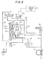
- FIG. 2 is a diagram showing the hydraulic circuit of the lock-up clutch 40.
- Line pressure delivered by an oil pump 41 is forwarded through a line 42 to a modulator valve 43 which adjusts it to a modulator pressure which is supplied through a line 44 to a solenoid valve (duty solenoid) 45.
- the solenoid valve 45 adjusts the modulator pressure to a duty pressure proportional to a duty value (ratio) and forwards it through a line 46 to a lock-up controller valve 47 which is urged thereby to the left in the drawing.
- the resulting movement of the lock-up controller valve 47 to the left allows line pressure forwarded through a line 48 to pass to a line 49.
- the lock-up clutch 40 comprises a piston 40a, a facing 40b adjacent to the piston 40a and integrally formed with the cover 22c (and the pump impeller 22a), and a clutch disc 40c inserted in a recess of the facing 40b.
- the hydraulic pressure of the line 49 sent to the torque converter 22 is supplied between the cover 22c and the piston 40a where it acts as a back pressure to force the piston 40a to the right in the drawing.
- a hydraulic pressure regulated to a fixed magnitude by a check valve 51 is supplied to between the lock-up clutch 40 and the turbine runner 22b as an internal pressure.
- the lock-up clutch 40 assumes engaged (to mechanically couple the pump impeller 22a and the turbine runner 22b), disengaged and slip states.
- a lock-up control unit 60 PWM (pulse width modulation) controls a solenoid valve 45 to a duty ratio within the range of 0 - 100%, thereby controlling the aforesaid duty pressure so as control the back pressure to the required value.
- the states assumed by the lock-up clutch depending on the relationship between the back and internal pressures are: Engagement: Back pressure >> internal pressure (very high duty pressure) Disengagement: Back pressure ⁇ internal pressure (very low duty pressure) Slip: Speed ratio varies and clutch slips depending on size of pressure difference.
- the back pressure is made inversely proportional to the duty ratio. Specifically, when the duty ratio is 0% the back pressure is 8 [kg/cm2] and when it is 100% the back pressure is 0 [kg/cm2]. In other words, the lock-up is progressively released with increasing duty ratio to become completely disengaged at a duty ratio of 100%.
- Reference numeral 52 in Figure 2 designates an oil cooler and 53 a regulator valve, Again returning to Figure 1, in the vicinity of the throttle valve 16 of the air intake passage 12 there is provided a throttle position sensor 62 such as a potentiometer or the like for detecting the degree of opening of the throttle valve 16. In the vicinity of a rotating member (e.g.
- crankshaft angle sensor 64 such as an electromagnetic pickup or the like.
- the crankshaft angle sensor 64 detects the position of the piston in terms of the crankshaft angle and produces a signal once every prescribed number of degrees of crankshaft rotation.
- an intake air pressure sensor 66 At an appropriate location downstream of the throttle valve 16 of the air intake passage 12 there is provided an intake air pressure sensor 66 for detecting the absolute pressure of the intake air.
- a brake switch 68 In the vicinity of the brake pedal (not shown) provided on the vehicle floor in the vicinity of the driver's seat there is provided a brake switch 68 for detecting depression of the brake pedal.
- a vehicle speed sensor 70 such as a reed switch or the like for detecting the vehicle road speed.
- an ATF (automatic transmission fluid) temperature sensor 72 is provided in the automatic transmission 20 for detecting the ATF temperature and a turbine speed sensor 74 is provided at an appropriate position on the main shaft 26 for detecting the turbine (runner) speed.
- the outputs of the sensors 62, 64, 66, 68, 70, 72 and 74 are sent to the lock-up control unit 60.
- Another control unit, the gear-shift control unit 80 is provided for controlling the gear ratio (gear position) of the gear box via a shift valve 82.
- the gear-shift control unit 80 will not be explained in detail.
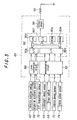
- FIG. 3 is a block diagram showing the lock-up control unit 60 in detail.
- the analog outputs from the throttle position sensor 62 and the like are input to a level conversion circuit 88 in the lock-up control unit 60 for amplification and the amplified signals are forwarded to a microcomputer 90.
- the microcomputer 90 has an input port 90a, an A/D (analog/digital) converter 90b, a CPU (central processing unit) 90c, a ROM (read-only memory) 90d, a RAM (random access memory) 90e, an output port 90f and groups of registers (not shown) and counters (not shown).
- the output from the level conversion circuit 88 is input to the A/D converter 90b whereby it is Converted into digital values, and the digital values are stored in the RAM 90e.
- the outputs from the crankshaft angle sensor 64 and the like are first waveshaped in a waveshaping circuit 92 and then input to the microcomputer through the input port 90a to be stored in the RAM 90e.
- the CPU 90c decides the duty ratio control value.
- the result of the decision is sent through the output port 90f to an output circuit 94 which energizes/deenergizes the solenoid valve 45 so as to control the operation of the lock-up clutch according to the target value.
- the system according to the invention has two fuzzy reasoning sections connected in series.
- the first fuzzy reasoning section decides the target speed ratio and the second fuzzy reasoning section feedback controls the duty ratio of the solenoid valve 45 for realizing the target speed ratio.
- the speed ratio e referred to here is the speed of the turbine shaft of the torque converter 22 divided by the speed of the pump shaft thereof.
- the target speed ratio is calculated by first obtaining the speed ratio change delta e from the input parameters through fuzzy reasoning using fuzzy production rules and then adding the result to the actual speed ratio:
- Target speed ratio en Speed ratio change delta e + Current speed ratio en-1 where n and n-1 indicate the values calculated (sampled) in the current and preceding cycles.
- the target duty ratio is obtained as:
- Target duty ratio DUTYn Duty ratio change delta DUTYn + Current duty ratio DUTYn-1 [%]
- Another feature of the system is that the number of fuzzy production rules used is minimized by organizing the rules hierarchically in line with an analysis of the vehicle operating states based on the decision-making process of human drivers.
- the target speed ratio decided on is thus checked in the light of the metarules.
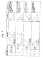
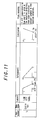
- the set of rules used in the first fuzzy reasoning section for deciding the target speed ratio are shown in Figures 6 - 8 and the set of rules used in the second fuzzy reasoning section for determining the target duty ratio (operation amount) are shown in Figures 9 - 11.
- the target values are obtained from the parameters included in the rule sets by fuzzy reasoning using membership functions.
- the parameters used by the rule sets are first detected/calculated in step S10.
- the parameters used in the first fuzzy reasoning section are the throttle opening ⁇ TH [0 - 84° (WOT)], the current speed ratio e , the torque converter turbine speed NT (rpm), the grade resistance (kg), the ATF temperature (°C), the tire speed (rpm) and the tire speed change (rps).
- the parameters used in the second fuzzy reasoning section are the speed ratio deviation E, the speed ratio deviation change delta E and the ATF temperature (°C).
- the suffixes a and b can indicate either the value calculated one cycle earlier or a value calculated several cycles earlier. Since the response of the speed ratio change is relatively slow, it is better to use values calculated several cycles earlier than to use those calculated in the preceding cycle.
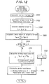
- the throttle opening ⁇ TH is obtained from the sensor detection value, the actual speed ratio e by dividing the turbine speed NT (sensor detection value) by the engine speed (calculated by counting the number of pulses output by the crankshaft angle sensor 64 per prescribed time period), and the ATF temperature from the sensor detection value. While the speed ratio deviation E and the speed ratio deviation change delta E are obtained as explained above, the grade resistance is calculated by a special method which will now be explained with reference to Figure 12.
- the actual horsepower is obtained, for example, by retrieval from a map stored in the ROM 90d beforehand, using the engine speed and the intake air pressure as address data.
- 716.2 is the constant conventionally used for converting horsepower to torque.
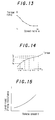
- control passes to step S102 in which a torque ratio TR indicative of the torque increase by the torque converter 22 is retrieved from a map, the characteristics of which is shown in Figure 13, to step S104 in which the torque calculated in step S100 is multiplied by the value retrieved in step S102, and to step S106 in which the mean value of the adjusted torque is calculated.
- step S110 [(Mean torque TRQ x Transmission efficiency eta x Overall gear ratio G/R)/Effective tire radius r) - [(1 + Equivalent mass) x Vehicle mass M x Acceleration ⁇ ] [kg]
- the transmission efficiency eta, overall gear ratio G/R, effective tire radius r, equivalent mass (equivalent mass coefficient) and vehicle mass M (ideal value) are obtained and stored in the ROM 90d in advance.
- Motive force F (Torque (mean) TRQ x Overall gear ratio G/R x Transmission efficiency eta)/Effective tire radius r
- Driving resistance R (Rolling resistance ⁇ O + Grade sin ⁇ ) x Vehicle gross weight Wr + Aerodynamic drag ( ⁇ A x V2)
- step S108 If it is found in step S108 that braking is being conducted, since the braking force makes it difficult to calculate the driving resistance with accuracy, control is passed to step S112 in which the value calculated in the preceding cycle is used.
- Control passes to step S114 in which the grade resistance is calculated by subtracting the level-road driving resistance from the driving resistance value obtained in the foregoing manner.
- the driving resistance is the sum of the rolling resistance, aerodynamic drag, grade resistance and acceleration resistance and the driving resistance value obtained in step S110 includes all of these other than the acceleration resistance, it is possible to get the grade resistance by subtracting the level-road driving resistance from said value.
- the level-road driving resistance is obtained by tests and stored in the ROM 90d in advance. It has the characteristics shown in Figure 15 and is retrieved for the calculation using the vehicle speed V as address data.
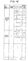
- the parameters are assigned parameter numbers (1 - 19) in advance as shown in Figure 16, and are thereafter identified by their parameter numbers.
- the membership functions for each parameter are assigned six function numbers (1 - 76) in order to simplify the processing.
- the throttle opening ⁇ TH which is used in rules 1, 2, 5 and 6, uses only three types of membership functions, namely the fuzzy set rising to the right shown for rule 1, the fuzzy set falling to the right shown for rule 2 and the pointed fuzzy set shown for rule 6.
- function numbers 4 - 6 have no content. Since the metarules 9 and 10 are used for final checking, as will be explained further later, the tire speed and the tire speed change used in these rules are not assigned parameter numbers.
- Control passes to step S12 in which the membership values used in the reasoning for deciding the speed ratio of the torque converter are calculated and then to step S14 in which the target speed ratio is calculated.
- step S12 the membership values used in the reasoning for deciding the speed ratio of the torque converter are calculated
- step S14 the target speed ratio is calculated.
- each rule consists of a premise (an IF part or antecedent) and a conclusion (THEN part or consequent), which is to say that it is written in the form of If ..., then ....
- rules 1 - 4 are basic rules relating to ordinary driving
- rules 5 - 8 are extra rules relating to special driving such as hill-climbing
- rules 9 and 10 are metarules of a restrictive nature.
- rule 1 states that if the throttle opening is large and the (current) torque converter speed ratio is large, the torque converter speed ratio is to be made smaller.
- This rule is established because depression of the accelerator pedal indicates the driver's desire to accelerate and for satisfying this desire, it is necessary to lower the speed ratio so as to increase the torque. (The speed ratio approaches 1.0 with increasing lockup clutch engagement and becomes 1.0 at full engagement.) It will be noted that the value of the conclusion membership function is maximum at -1.0. This indicates that the torque converter speed ratio is to be adjusted greatly in the negative direction, i.e. in the disengagement direction.
- Rule 2 stipulates that under conditions the opposite from those premised by rule 1, the lock-up clutch is to be engaged for increasing fuel economy.
- Rule 3 stipulates that when the turbine speed is high, the torque converter speed ratio is to be made large. The thinking behind this is that a high turbine speed, i.e. a high vehicle speed, means that the engine speed is high and driving is possible without a torque increase, so that the torque converter speed ratio should be increased, which is also appropriate from the point of minimizing vehicle vibration.
- Rule 4 relates to the opposite situation.
- Rule 5 stipulates that if the throttle opening is large during hill-climbing, then the torque converter speed ratio should be made small. This is for increasing the motive force.
- Rule 7 which calls for the torque converter speed ratio to be increased when the ATF temperature is high, is established to prevent further temperature increase by lowering heat generation, which increases in proportion to torque converter slip.
- the reason for stipulating in rule 8 that the torque converter speed ratio is to be made smaller when the ATF temperature is low is to counteract the tendency for the high viscosity of low-temperature ATF to increase transmission of engine vibration and give rise to vehicle vibration.
- Skipping rule 9 for the moment, in rule 10 the idea behind disengaging the lock-up clutch when the change in the tire speed is very large in the negative direction is to prevent stalling of the engine when the wheels are locked, as may happen for example during rapid braking on snow.
- Rule 9 is for backing up rule 10 in a case where the rapid braking is not detected for some reason.
- steps S12 and S14 the detected parameters relating to the antecedent (IF part) of each rule are applied to the corresponding membership functions, the values (called membership values or membership grades) at the positions on the vertical axes corresponding to the points of intersection are read, and the smallest of the values is taken as the degree of satisfaction of the rule.
- the output value of the consequent of each rule is weighted by the degree of satisfaction of its antecedent and the weighted mean of the outputs of all of the consequent is calculated to obtain the final output.
- the calculation of the membership values in step S12 starts with calculation of membership values for the parameters used in the rule set and the association of the calculated values with the corresponding function numbers. As shown by the specific example in Figure 16, this would mean, for instance, beginning the association of values and function numbers by reading the value 0.3 for function number 1.
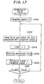
- Figure 17 is a flow chart showing a subroutine for calculating the membership values.
- the subroutine starts with the step S200 in which initialization is conducted for setting the parameter number to 1 (throttle opening). Control then passes to step S202 for reading out the size of the fuzzy sub-number set associated with this parameter number, namely, the number of different membership functions in which the parameter is used (three in the case of the throttle opening). Then in the following step S204, the count value of a counter COUNT for counting the size of the fuzzy sub-number set is initialized by setting to 1, whereafter the membership value is retrieved in step S206.
- step S300 the count value is compared with the size of fuzzy sub-number set.
- the count value is naturally found to be smaller than the sub-number set so that control passes to step S302 in which the function number is calculated as (6 x (Parameter number - 1) + COUNT), to step S304 in which the membership value is read, to step S306 in which the read value is written to an appropriate address in the RAM 90e, and finally to step S308 in which the value of COUNT is incremented.
- step S300 This process is repeated until it is found in step S300 that the value of COUNT has exceeded the size fuzzy sub-number set, and when this happens, control returns to the subroutine of Figure 17 where, in step S208, the parameter number is incremented and the same processes is repeated.
- step S210 the parameter number has become 19 or larger, the subroutine is terminated.
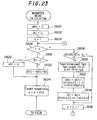
- control reverts to the subroutine of Figure 4, passing to step S14 in which the target speed ratio is decided.
- Figure 19 shows the subroutine for deciding the target speed ratio.
- the count value of a counter N is initialized by setting it to the number of rules required for the reasoning NLC (8 in this embodiment).
- Control passes to step S404 in which the degree of satisfaction of the antecedent is retrieved.
- step S500 the count value of a counter K is set to the number of rules retrieved so far, namely to 1 the first time the subroutine is activated.
- step S502 the value of GRADE indicating the minimum degree of satisfaction of the rule up to the present is initialized by setting it to an appropriate value such as 1.0.
- step S504 the number of rules retrieved so far (K) is compared with the number of rules required for the reasoning (N).
- step S506 the count value of the rule antecedent label number counter LO of the currently retrieved rule is initialized by setting it to 1.
- step S508 the function number FO of the (L + K -1)th rule is read.
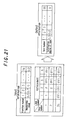
- Figure 21 the membership values corresponding to the function numbers have already been read, while the parameters used in the respective rules are progressively numbered (with the aforesaid label numbers). Taking rule 1 as an example, since the parameters used are the throttle opening ⁇ TH and the actual speed ratio e, the first throttle opening is assigned label number 1 and the first speed ratio is assigned the label number 2.
- step S510 the value of the function number is compared with a prescribed value, e.g. 255.
- a prescribed value e.g. 255.
- the procedure goes to step S512 in which the label number is compared with the maximum number (6).
- the result is of course negative and control passes to step S514 where it is discriminated whether or not the value read in step S508 is equal to zero.
- step 516 If it is found not to be zero, control passes to step 516 in which it is compared with the value of GRADE (initial value 1), and if it is found to be smaller than the GRADE value, the value of GRADE is replaced with the value of MYUGRD (FO) in step S518 and this value is taken as the minimum degree of satisfaction up to this point.
- This label number is then incremented in the following step S520, whereafter the same procedures are repeated with respect to the next parameter (the speed ratio in case the case of rule 1).
- the membership values of the parameters for the respective rules are progressively retrieved and the minimum value for each rule is selected.
- step S528 the GRADE value is defined as the degree of satisfaction of the rule and then to step S526 in which the rule number counter is incremented.
- the degrees of satisfaction (minimum membership values) of the respective rules are progressively determined.
- step S600 and S602 the values of WMS and WS stored in the RAM 90e are initialized by setting them to zero. (These values will be explained later.)
- Control then passes to step S604 in which the count value of the rule number counter K is set to a value 1 (rule 1) and then to step S606 in which this set value is compared with the count value of the counter N indicating the total number of rules required for the reasoning.
- this subroutine is activated, the relationship will of course be found to be K ⁇ N so that control passes to step S608 in which it is judged whether or not the degree of satisfaction of rule 1 retrieved earlier is zero.
- step S608 When it is found in step S608 that the retrieved value is not zero, control passes to step S610 in which the consequent number FA of the (L + K - 1)th rule is read.
- the membership function has a waveform which, in line with the statement " ... then make the speed ratio smaller,” peaks at a conclusion of -1.0, as was mentioned earlier.
- the speed ratio conclusions i.e. the center of gravity positions and weights, are separated into categories in advance by assignment of consequent function numbers as shown in Figure 24.
- Control passes to step S612 in which the value of WMS to be stored in RAM is calculated, to step S614 in which the value of WS to be stored in RAM is calculated, and to step S616 in which the rule number counter is incremented.
- step S612 the degree of satisfaction of the antecedent is 0.3 in the case of rule 1 and is 0.2 in the case of rule 2.
- the center of gravity of the consequent of rule 1 becomes -1/3 and that of rule 2 becomes +1/3, while the weight thereof becomes 1.0 in the case of rule 1 and 0.8 in the case of rule 2. Therefore, as shown, the weighted mean becomes
- a simplified method for determining the weighted mean is used in this embodiment. Specifically, at the time of calculating the value of the consequent from the degrees of rule satisfaction, instead of truncating the triangular configurations at the positions concerned, triangular configurations (indicated by hatching) are formed having apices at these positions (at 0.3 and 0.2 in the illustrated example) and the resulting triangles are summed at the time of being transferred to a common universe of discourse. As shown in the figure, it is possible to realize a further simplification by using a fixed weighting.
- WMS in step S612 corresponds to the numerator of the above equation while WS in step S614 corresponds to the denominator thereof.
- steps S606 - S616 By repeatedly executing the steps S606 - S616 in a loopwise manner while adding the value obtained during each loop to the total for the preceding loops, it is possible to obtain separate sums for the numerators and the denominators with respect to rules 1 - 8.
- step S606 it is found in step S606 that the rule number has come to exceed the number of rules to be retrieved, the procedure moves to step S618 in which judgment is made as to whether or not WS is zero, and if the result is negative, WMS is divided by WS in step S620 to obtain the quotient ANS.
- step S618 If WS is found to be zero in step S618, the quotient ANS is set to zero in step S622. Control then passes to step S624 in which the quotient ANS ( delta e ) is added to the current speed ratio e to obtain the target speed ratio.
- step S408 in which the final target gear speed ratio is decided.
- Figure 26 shows a subroutine for making this decision.
- the membership value of rules 9 and 10 is calculated.
- Control passes to step S702 in which a discrimination is made as to whether the membership value calculated in step S702 is 1.0, and if it is, to step S704 in which the once-decided target speed ratio e is set to zero. If the result of the discrimination in step S702 is negative, the program is immediately terminated.
- This type of check is made in view of the fact that the metarules stipulate absolutely prohibited conditions. By carrying out the processing of the metarules independently of that for the other rules in this way, it is possible to give priority to absolute restrictions under specified conditions and thus possible to cope with rapid braking in a panic, for example.
- the fuzzy reasoning is conducted in two successive steps because, owing to the implementation of the control through hydraulic pressure, the actual speed ratio would not immediately follow the target speed ratio decided through the fuzzy reasoning should it be directly used to operate the solenoid valve.
- the second fuzzy reasoning is therefore conducted for ensuring that the actual speed ratio properly follows the target value. Fuzzy reasoning is used because it is well adapted to control for enhancing following characteristics.
- the target speed ratio value is 0.5 and the current speed ratio is 0.25
- the change is in the negative direction, i.e. away from the target value.
- the duty ratio is decreased to adjust the clutch in the direction of engagement.
- Rule 15 comes into play when the current speed ratio is in the vicinity of the target value, i.e. when the speed ratio deviation is near zero, and stipulates that under such circumstances if the second difference also indicates no change, the target value is to be left unchanged.
- Rules 16 and 17 deal with the opposite situation, namely cases in which the deviation between the current and target values is very large, and, therefore, as indicated in the figure, stipulate that the amount of operation (delta duty ratio) is to be made very large.
- Rules 18 and 19 specify that the amount of operation is to be made very large in the negative (positive) direction when the ATF temperature is low and deviation is large in the positive (negative) direction. The reason for this is that the response of the hydraulic pressure is slow when the ATF temperature is low.
- the present embodiment decides the target speed ratio by conducting fuzzy reasoning on the basis of production rules which additionally include the grade resistance as a parameter and then decides the duty ratio control value (operation amount) by conducting a second fuzzy reasoning using the deviation between the so-decided target speed ratio and the current speed ratio.
- the system of this embodiment recognizes and conducts fuzzy reasoning on the basis of driving conditions that include the grade resistance, and because of this, can achieve lock-up clutch engagement control that is matched to a broad range of driving states.
- the system is able to simultaneously optimize drivability, fuel economy, noise suppression and the like, as can be seen, for example, from its ability to provide control which engages the lock-up clutch during gentle hill-climbing so as to enhance fuel economy but which disengages the lock-up clutch during steep hill-climbing so as to obtain greater torque increase.
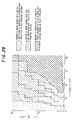
- Figure 28 shows the lock-up clutch control region according to the prior art control using map retrieval and Figure 29 shows that according to the present invention control. It will be noted that the invention markedly expands the control region beyond that of the prior art. Moreover, differently from the system taught by Japanese Laid-open Patent Publication No. 3(1991)-103665 referred to earlier, which enables ON/OFF control between lock-up clutch engagement/disengagement only in the third and fourth gears of the D range, the system according to this invention, operating through its control of the lock-up speed ratio, controls the engaged, disengaged and semi-engaged states of the lock-up clutch in all gear positions.
- the invention system facilitates the creation of a knowledge base and enables the control rules to be formulated in the manner of a dialogue, making it easier to incorporate the control know-how acquired by an experienced driver in operating a vehicle with a manual transmission. Another advantage is the ease with which the control rules shown in Figures 6 - 11 can be modified.
- the hierarchical organization of the fuzzy production rules according to the invention makes it possible to reduce the number of rules required to the very minimum, while the expedient employed during fuzzy reasoning of specifying the parameters and the like by numbers assigned thereto and of consolidating the individual processing operations by type in advance enables the processing to be simplified and the processing time to be shortened.
- the grade resistance is obtained by subtracting the level-driving resistance from the total driving resistance, the cost of the sensor system is reduced and the grade resistance can be obtained with higher accuracy than in the prior art systems.
- Control including the lock-up clutch control can be broadly classified into position type control and speed type control. If anything, the prior art systems fall into the category of position type control. In contrast, the embodiment of this invention described above conducts speed type control in which the value obtained through fuzzy reasoning is added to the current value obtained through calculating the amount of change, whereby the operations and intentions of a human driver can be reflected in the control to a higher degree than is possible in the prior art systems.
- position type control absolute positional operations
- speed type control in the proper sense of the term.
- position type control a separate rule has to be written to express the characteristics of every combination of possible current and post-control values. For example, for specifying the gear position of a transmission with four forward speeds in position type control, it becomes necessary to establish rules in the manner of "IF in first gear ..., THEN stay in first gear,” “IF in second gear ..., THEN stay in second gear,” “IF in fourth gear ...
- the invention uses an arrangement in which the fuzzy reasoning for deciding the target speed ratio and the fuzzy reasoning for deciding the target duty ratio are conducted separately in two stages, the invention is not limited to this and it is alternatively possible to decide the target duty ratio immediately on the basis of the rules set out in the figures. Also, while the embodiment decides the target duty ratio through further fuzzy reasoning conducted on the basis of the target speed ratio obtained, the invention is not limited to this arrangement and it is alternatively possible to decided the target duty value using PID control, modern theory control or the like.
- Figure 4 shows a case in which the first and second fuzzy reasoning are conducted by the same program, i.e. with the same control period, the invention is not limited to this arrangement and it is alternatively possible to conduct them using different control periods.
- grade resistance was obtained by calculation in the foregoing embodiment, it is alternatively possible to obtain it from the output of a separately provided grade sensor.
Landscapes
- Engineering & Computer Science (AREA)
- General Engineering & Computer Science (AREA)
- Mechanical Engineering (AREA)
- Control Of Fluid Gearings (AREA)
- Feedback Control In General (AREA)
Applications Claiming Priority (2)
| Application Number | Priority Date | Filing Date | Title |
|---|---|---|---|
| JP3263012A JP2710080B2 (ja) | 1991-09-14 | 1991-09-14 | 自動変速機のロックアップクラッチの制御装置 |
| JP263012/91 | 1991-09-14 |
Publications (2)
| Publication Number | Publication Date |
|---|---|
| EP0533419A1 true EP0533419A1 (fr) | 1993-03-24 |
| EP0533419B1 EP0533419B1 (fr) | 1996-04-17 |
Family
ID=17383665
Family Applications (1)
| Application Number | Title | Priority Date | Filing Date |
|---|---|---|---|
| EP92308340A Expired - Lifetime EP0533419B1 (fr) | 1991-09-14 | 1992-09-14 | Système de commande d'embrayage à verrouillage pour une transmission automatique de véhicule |
Country Status (5)
| Country | Link |
|---|---|
| US (1) | US5267158A (fr) |
| EP (1) | EP0533419B1 (fr) |
| JP (1) | JP2710080B2 (fr) |
| CA (1) | CA2077424C (fr) |
| DE (1) | DE69209951T2 (fr) |
Cited By (9)
| Publication number | Priority date | Publication date | Assignee | Title |
|---|---|---|---|---|
| EP0636818A3 (fr) * | 1993-07-28 | 1995-11-08 | Aisin Aw Co | Système de commande hydraulique pour une transmission de véhicule automatique. |
| US5527233A (en) * | 1993-04-26 | 1996-06-18 | Toyota Jidosha Kabushiki Kaisha | Hydraulic control apparatus for controlling an engaging state of a lock-up clutch of an automatic transmission |
| EP0800124A1 (fr) * | 1996-04-03 | 1997-10-08 | General Motors Corporation | Système de régulation adaptif de changements de vitesse utilisant la logique floue |
| EP0781945A3 (fr) * | 1995-12-29 | 1998-03-25 | Hyundai Motor Company | Système de commande à logique floue de l'accouplement de pontage d'un convertisseur de couple |
| EP0870953A1 (fr) * | 1997-04-07 | 1998-10-14 | Ford Global Technologies, Inc. | Système de régulation à rétroaction adaptatif utilisant la logique floue pour la commande de pression d'une transmission automatique |
| EP0872668A1 (fr) * | 1997-04-14 | 1998-10-21 | Mazda Motor Corporation | ContrÔle de l'application de l'embrayage de pontage du convertisseur dans un véhicule avec transmission automatique |
| EP0907043A1 (fr) * | 1997-10-01 | 1999-04-07 | Honda Giken Kogyo Kabushiki Kaisha | Dispositif de commande de pontage d'un convertisseur de couple |
| EP0926405A3 (fr) * | 1997-12-19 | 2000-09-13 | Mazda Motor Corporation | Système de commande pour l'embrayage de pontage d'un convertisseur de couple hydrodynamique |
| EP1288533A3 (fr) * | 2001-09-04 | 2006-04-12 | Caterpillar Inc. | Machine de travail avec transmission comportant un mode de freinage moteur renforcé |
Families Citing this family (23)
| Publication number | Priority date | Publication date | Assignee | Title |
|---|---|---|---|---|
| DE4240762A1 (en) * | 1991-12-03 | 1993-06-09 | Hitachi, Ltd., Tokio/Tokyo, Jp | Automatic gearbox control for motor vehicle - uses vehicle wt. calculator, output torque estimator and stored gear setting tables to select gear taking into account required acceleration |
| USRE39684E1 (en) * | 1991-12-03 | 2007-06-05 | Hitachi, Ltd. | Automatic automobile transmission with variable shift pattern controlled in response to estimated running load |
| US5377108A (en) * | 1992-04-28 | 1994-12-27 | Takata Corporation | Method for predicting impact and an impact prediction system for realizing the same by using neural networks |
| DE4328893B4 (de) * | 1992-08-27 | 2007-07-05 | Hitachi, Ltd. | Verfahren und Einrichtung zur Steuerung eines Automatikgetriebes eines Fahrzeugs in Abhängigkeit von einem Gefälle einer Fahrbahn |
| JPH0694116A (ja) * | 1992-09-08 | 1994-04-05 | Hitachi Ltd | 自動変速制御装置 |
| US5341703A (en) * | 1993-03-04 | 1994-08-30 | Ford Motor Company | Performance mode and economy mode shift scheduling in an automatic transmission |
| JP3294680B2 (ja) * | 1993-08-09 | 2002-06-24 | 本田技研工業株式会社 | 車両用無段変速機の変速制御装置 |
| EP0739465B1 (fr) * | 1994-01-19 | 2001-06-06 | Siemens Aktiengesellschaft | Commande pour boite de vitesses automatique d'automobile |
| US5743829A (en) * | 1995-02-22 | 1998-04-28 | Honda Giken Kogyo Kabushiki Kaisha | Control system for vehicle automatic transmission |
| JP3127350B2 (ja) * | 1995-07-20 | 2001-01-22 | 本田技研工業株式会社 | ロックアップクラッチの制御装置 |
| JP3484836B2 (ja) * | 1995-08-24 | 2004-01-06 | トヨタ自動車株式会社 | 車両用直結クラッチのスリップ制御装置 |
| US5777211A (en) * | 1996-11-25 | 1998-07-07 | Chrysler Corporation | Method to determine the remaining useful life of automatic transmission fluid |
| JP3240979B2 (ja) * | 1997-11-04 | 2001-12-25 | 日産自動車株式会社 | トルクコンバータのスリップ制御装置 |
| US6625535B2 (en) | 2001-08-17 | 2003-09-23 | General Motors Corporation | Adaptive powertrain braking control with grade, mass, and brake temperature |
| JP3912254B2 (ja) * | 2002-10-28 | 2007-05-09 | 日産自動車株式会社 | トルクコンバータのスリップ制御装置 |
| JP3873899B2 (ja) * | 2003-02-13 | 2007-01-31 | 日産自動車株式会社 | トルクコンバータのスリップ制御装置 |
| JP2006300144A (ja) * | 2005-04-18 | 2006-11-02 | Toyota Motor Corp | 自動変速機の制御装置 |
| JP4420060B2 (ja) * | 2007-04-26 | 2010-02-24 | トヨタ自動車株式会社 | 自動変速機の制御装置 |
| FR2933462B1 (fr) * | 2008-07-04 | 2010-07-30 | Inst Francais Du Petrole | Procede pour controler la phase de fermeture d'un embrayage d'un systeme de transmission robotisee automobile |
| US8630778B2 (en) * | 2008-08-08 | 2014-01-14 | Honda Motor Co., Ltd. | Controlling a throttle for fuel cut acquisition |
| US10037374B2 (en) * | 2015-01-30 | 2018-07-31 | Qualcomm Incorporated | Measuring semantic and syntactic similarity between grammars according to distance metrics for clustered data |
| JP6372621B2 (ja) * | 2015-10-23 | 2018-08-15 | 日産自動車株式会社 | 車両のロックアップ制御方法及び制御装置 |
| WO2019221067A1 (fr) * | 2018-05-14 | 2019-11-21 | ジヤトコ株式会社 | Dispositif de commande de blocage pour transmission automatique |
Citations (4)
| Publication number | Priority date | Publication date | Assignee | Title |
|---|---|---|---|---|
| EP0126201A1 (fr) * | 1983-04-23 | 1984-11-28 | WABCO Westinghouse Fahrzeugbremsen GmbH | Dispositif de contrôle pour un véhicule propulsé par un moteur par l'intermédiaire d'une transmission à étages |
| US4957194A (en) * | 1987-09-08 | 1990-09-18 | Mazda Motor Corporation | Torque converter slip control device |
| EP0410223A2 (fr) * | 1989-07-24 | 1991-01-30 | Ford-Werke Aktiengesellschaft | Système de commande électronique pour l'accouplement de pontage d'un convertisseur de couple |
| US5095435A (en) * | 1989-08-25 | 1992-03-10 | Toyota Jidosha Kabushiki Kaisha | Apparatus for controlling lock-up clutch in vehicle automatic transmission according to fuzzy set theory |
Family Cites Families (16)
| Publication number | Priority date | Publication date | Assignee | Title |
|---|---|---|---|---|
| US4261229A (en) * | 1978-08-24 | 1981-04-14 | Aisin Seiki Kabushiki Kaisha | Automatic speed ratio control system for stepless transmission of automotive vehicles |
| US5115395A (en) * | 1987-03-13 | 1992-05-19 | Borg-Warner Automotive, Inc. | Pulse width modulation technique |
| JP2584765B2 (ja) * | 1987-03-31 | 1997-02-26 | 日産自動車株式会社 | 自動変速機の変速制御装置 |
| JPH081243B2 (ja) * | 1988-02-12 | 1996-01-10 | 日産自動車株式会社 | 自動変速機の制御装置 |
| US5036730A (en) * | 1988-06-17 | 1991-08-06 | Honda Giken Kogyo Kabushiki Kaisha | Vehicle automatic transmission control system |
| US5079704A (en) * | 1988-11-18 | 1992-01-07 | Honda Giken Kogyo Kabushiki Kaisha | Vehicle automatic transmission control system |
| JP2993970B2 (ja) * | 1989-02-10 | 1999-12-27 | マツダ株式会社 | 流体継手のスリップ制御装置 |
| JP2956074B2 (ja) * | 1989-08-24 | 1999-10-04 | トヨタ自動車株式会社 | 自動変速機の変速制御装置 |
| JPH03103665A (ja) * | 1989-09-14 | 1991-04-30 | Toyota Motor Corp | 自動変速機のロツクアツプクラツチの制御装置 |
| JPH03121354A (ja) * | 1989-10-03 | 1991-05-23 | Toyota Motor Corp | 自動変速機の変速制御装置 |
| JP2621509B2 (ja) * | 1989-10-06 | 1997-06-18 | トヨタ自動車株式会社 | 車両用無段変速機の変速制御装置 |
| JPH03163259A (ja) * | 1989-11-20 | 1991-07-15 | Toyota Motor Corp | 自動変速機の変速段制御装置 |
| US5148721A (en) * | 1990-03-12 | 1992-09-22 | Mazda Motor Corporation | Automatic fuzzy speed control system for vehicle |
| JPH0460A (ja) * | 1990-04-13 | 1992-01-06 | Toyota Motor Corp | 自動変速機の直結クラッチ制御装置 |
| US5121820A (en) * | 1990-12-24 | 1992-06-16 | Ford Motor Company | Feedforward control for automatic transmission torque converter bypass clutch slip |
| US5123302A (en) * | 1990-12-24 | 1992-06-23 | Ford Motor Company | Automatic transmission gearshift control having feedforward response of clutch and its hydraulic actuation |
-
1991
- 1991-09-14 JP JP3263012A patent/JP2710080B2/ja not_active Expired - Lifetime
-
1992
- 1992-09-02 CA CA002077424A patent/CA2077424C/fr not_active Expired - Fee Related
- 1992-09-04 US US07/940,487 patent/US5267158A/en not_active Expired - Lifetime
- 1992-09-14 EP EP92308340A patent/EP0533419B1/fr not_active Expired - Lifetime
- 1992-09-14 DE DE69209951T patent/DE69209951T2/de not_active Expired - Fee Related
Patent Citations (4)
| Publication number | Priority date | Publication date | Assignee | Title |
|---|---|---|---|---|
| EP0126201A1 (fr) * | 1983-04-23 | 1984-11-28 | WABCO Westinghouse Fahrzeugbremsen GmbH | Dispositif de contrôle pour un véhicule propulsé par un moteur par l'intermédiaire d'une transmission à étages |
| US4957194A (en) * | 1987-09-08 | 1990-09-18 | Mazda Motor Corporation | Torque converter slip control device |
| EP0410223A2 (fr) * | 1989-07-24 | 1991-01-30 | Ford-Werke Aktiengesellschaft | Système de commande électronique pour l'accouplement de pontage d'un convertisseur de couple |
| US5095435A (en) * | 1989-08-25 | 1992-03-10 | Toyota Jidosha Kabushiki Kaisha | Apparatus for controlling lock-up clutch in vehicle automatic transmission according to fuzzy set theory |
Non-Patent Citations (4)
| Title |
|---|
| PATENT ABSTRACTS OF JAPAN vol. 014, no. 514 (M-1046)13 November 1990 & JP-A-02 212 668 ( MAZDA ) 23 August 1990 * |
| PATENT ABSTRACTS OF JAPAN vol. 015, no. 290 (M-1139)23 July 1991 & JP-A-03 103 665 ( TOYOTA ) 30 April 1991 * |
| PATENT ABSTRACTS OF JAPAN vol. 015, no. 329 (M-1149)21 August 1991 & JP-A-03 125 062 ( TOYOTA ) 28 May 1991 * |
| PATENT ABSTRACTS OF JAPAN vol. 016, no. 137 (M-1231)7 April 1992 & JP-A-04 000 060 ( TOYOTA ) 6 January 1992 * |
Cited By (13)
| Publication number | Priority date | Publication date | Assignee | Title |
|---|---|---|---|---|
| US5527233A (en) * | 1993-04-26 | 1996-06-18 | Toyota Jidosha Kabushiki Kaisha | Hydraulic control apparatus for controlling an engaging state of a lock-up clutch of an automatic transmission |
| EP0636818A3 (fr) * | 1993-07-28 | 1995-11-08 | Aisin Aw Co | Système de commande hydraulique pour une transmission de véhicule automatique. |
| AU721738B2 (en) * | 1995-12-29 | 2000-07-13 | Hyundai Motor Company | Fuzzy control method of damper clutch |
| EP0781945A3 (fr) * | 1995-12-29 | 1998-03-25 | Hyundai Motor Company | Système de commande à logique floue de l'accouplement de pontage d'un convertisseur de couple |
| US5737712A (en) * | 1996-04-03 | 1998-04-07 | General Motors Corporation | Fuzzy logic adaptive shift control |
| EP0800124A1 (fr) * | 1996-04-03 | 1997-10-08 | General Motors Corporation | Système de régulation adaptif de changements de vitesse utilisant la logique floue |
| EP0870953A1 (fr) * | 1997-04-07 | 1998-10-14 | Ford Global Technologies, Inc. | Système de régulation à rétroaction adaptatif utilisant la logique floue pour la commande de pression d'une transmission automatique |
| EP0872668A1 (fr) * | 1997-04-14 | 1998-10-21 | Mazda Motor Corporation | ContrÔle de l'application de l'embrayage de pontage du convertisseur dans un véhicule avec transmission automatique |
| US5976055A (en) * | 1997-04-14 | 1999-11-02 | Mazda Motor Corporation | Lockup force control apparatus for fluid coupling in vehicle with automatic transmission |
| EP0907043A1 (fr) * | 1997-10-01 | 1999-04-07 | Honda Giken Kogyo Kabushiki Kaisha | Dispositif de commande de pontage d'un convertisseur de couple |
| US6314357B1 (en) | 1997-10-01 | 2001-11-06 | Honda Giken Kogyo Kabushiki Kaisha | Lock-up control device |
| EP0926405A3 (fr) * | 1997-12-19 | 2000-09-13 | Mazda Motor Corporation | Système de commande pour l'embrayage de pontage d'un convertisseur de couple hydrodynamique |
| EP1288533A3 (fr) * | 2001-09-04 | 2006-04-12 | Caterpillar Inc. | Machine de travail avec transmission comportant un mode de freinage moteur renforcé |
Also Published As
| Publication number | Publication date |
|---|---|
| DE69209951D1 (de) | 1996-05-23 |
| JPH0571639A (ja) | 1993-03-23 |
| CA2077424A1 (fr) | 1993-03-15 |
| DE69209951T2 (de) | 1996-11-07 |
| US5267158A (en) | 1993-11-30 |
| EP0533419B1 (fr) | 1996-04-17 |
| CA2077424C (fr) | 1997-04-15 |
| JP2710080B2 (ja) | 1998-02-10 |
Similar Documents
| Publication | Publication Date | Title |
|---|---|---|
| EP0533419B1 (fr) | Système de commande d'embrayage à verrouillage pour une transmission automatique de véhicule | |
| CA2077425C (fr) | Systeme de commande de verrouillage de transmission automatique pour vehicule | |
| EP0531154B1 (fr) | Système de commande de transmission automatique de véhicule | |
| EP0347263B1 (fr) | Système de commande pour la transmission automatique d'un véhicule | |
| US5303153A (en) | Vehicle automatic transmission control system | |
| EP0375155B1 (fr) | Systèmes de commande d'une transmission automatique pour véhicule automobile | |
| US5079705A (en) | Vehicle automatic transmission control system | |
| US5776031A (en) | Power train controller and control method | |
| EP0377953B1 (fr) | Système de commande de transmission automatique de véhicule | |
| US5319555A (en) | Vehicle automatic transmission control system for controlling the speed change ratio based on driving resistance | |
| US5857161A (en) | System for determining a gear ratio change in an automatic transmission | |
| EP0559255B1 (fr) | Procédé de commande d'une transmission automatique | |
| EP0532364B1 (fr) | Système de commande de transmission automatique de véhicule | |
| JPH07174219A (ja) | 車両用変速装置 | |
| JPH06344802A (ja) | 自動車一定速走行制御装置 | |
| JPH05196123A (ja) | 自動変速機の制御装置 | |
| JP2738206B2 (ja) | 車両用自動変速機の変速制御方法 | |
| EP0781945B1 (fr) | Système de commande à logique floue de l'accouplement de pontage d'un convertisseur de couple | |
| JPH02138561A (ja) | 自動変速機の制御装置 | |
| JPH0571620A (ja) | 自動変速機を含む車両の制御装置 | |
| Maschmedt | Chassis Design Engineer | |
| JPH0565956A (ja) | 自動変速機の制御装置 | |
| JPH0581792B2 (fr) | ||
| JP2003307272A (ja) | 無段階変速機の制御装置 | |
| JPH0571621A (ja) | 自動変速機の制御装置 |
Legal Events
| Date | Code | Title | Description |
|---|---|---|---|
| PUAI | Public reference made under article 153(3) epc to a published international application that has entered the european phase |
Free format text: ORIGINAL CODE: 0009012 |
|
| AK | Designated contracting states |
Kind code of ref document: A1 Designated state(s): DE FR GB |
|
| 17P | Request for examination filed |
Effective date: 19930707 |
|
| 17Q | First examination report despatched |
Effective date: 19940727 |
|
| GRAH | Despatch of communication of intention to grant a patent |
Free format text: ORIGINAL CODE: EPIDOS IGRA |
|
| GRAA | (expected) grant |
Free format text: ORIGINAL CODE: 0009210 |
|
| AK | Designated contracting states |
Kind code of ref document: B1 Designated state(s): DE FR GB |
|
| REF | Corresponds to: |
Ref document number: 69209951 Country of ref document: DE Date of ref document: 19960523 |
|
| ET | Fr: translation filed | ||
| PLBE | No opposition filed within time limit |
Free format text: ORIGINAL CODE: 0009261 |
|
| 26N | No opposition filed | ||
| PGFP | Annual fee paid to national office [announced via postgrant information from national office to epo] |
Ref country code: FR Payment date: 20000912 Year of fee payment: 9 |
|
| PGFP | Annual fee paid to national office [announced via postgrant information from national office to epo] |
Ref country code: GB Payment date: 20000913 Year of fee payment: 9 |
|
| PG25 | Lapsed in a contracting state [announced via postgrant information from national office to epo] |
Ref country code: GB Free format text: LAPSE BECAUSE OF NON-PAYMENT OF DUE FEES Effective date: 20010914 |
|
| PGFP | Annual fee paid to national office [announced via postgrant information from national office to epo] |
Ref country code: DE Payment date: 20011001 Year of fee payment: 10 |
|
| REG | Reference to a national code |
Ref country code: GB Ref legal event code: IF02 |
|
| GBPC | Gb: european patent ceased through non-payment of renewal fee |
Effective date: 20010914 |
|
| PG25 | Lapsed in a contracting state [announced via postgrant information from national office to epo] |
Ref country code: FR Free format text: LAPSE BECAUSE OF NON-PAYMENT OF DUE FEES Effective date: 20020531 |
|
| REG | Reference to a national code |
Ref country code: FR Ref legal event code: ST |
|
| PG25 | Lapsed in a contracting state [announced via postgrant information from national office to epo] |
Ref country code: DE Free format text: LAPSE BECAUSE OF NON-PAYMENT OF DUE FEES Effective date: 20030401 |