EP0533484A2 - Bilderzeugungsgerät - Google Patents
Bilderzeugungsgerät Download PDFInfo
- Publication number
- EP0533484A2 EP0533484A2 EP92308510A EP92308510A EP0533484A2 EP 0533484 A2 EP0533484 A2 EP 0533484A2 EP 92308510 A EP92308510 A EP 92308510A EP 92308510 A EP92308510 A EP 92308510A EP 0533484 A2 EP0533484 A2 EP 0533484A2
- Authority
- EP
- European Patent Office
- Prior art keywords
- cartridge
- developing unit
- bearing member
- image
- mode
- Prior art date
- Legal status (The legal status is an assumption and is not a legal conclusion. Google has not performed a legal analysis and makes no representation as to the accuracy of the status listed.)
- Granted
Links
Images


Classifications
-
- G—PHYSICS
- G03—PHOTOGRAPHY; CINEMATOGRAPHY; ANALOGOUS TECHNIQUES USING WAVES OTHER THAN OPTICAL WAVES; ELECTROGRAPHY; HOLOGRAPHY
- G03G—ELECTROGRAPHY; ELECTROPHOTOGRAPHY; MAGNETOGRAPHY
- G03G21/00—Arrangements not provided for by groups G03G13/00 - G03G19/00, e.g. cleaning, elimination of residual charge
- G03G21/16—Mechanical means for facilitating the maintenance of the apparatus, e.g. modular arrangements
- G03G21/18—Mechanical means for facilitating the maintenance of the apparatus, e.g. modular arrangements using a processing cartridge, whereby the process cartridge comprises at least two image processing means in a single unit
- G03G21/1803—Arrangements or disposition of the complete process cartridge or parts thereof
- G03G21/1807—Arrangements or disposition of the complete process cartridge or parts thereof colour
-
- G—PHYSICS
- G03—PHOTOGRAPHY; CINEMATOGRAPHY; ANALOGOUS TECHNIQUES USING WAVES OTHER THAN OPTICAL WAVES; ELECTROGRAPHY; HOLOGRAPHY
- G03G—ELECTROGRAPHY; ELECTROPHOTOGRAPHY; MAGNETOGRAPHY
- G03G15/00—Apparatus for electrographic processes using a charge pattern
- G03G15/01—Apparatus for electrographic processes using a charge pattern for producing multicoloured copies
-
- G—PHYSICS
- G03—PHOTOGRAPHY; CINEMATOGRAPHY; ANALOGOUS TECHNIQUES USING WAVES OTHER THAN OPTICAL WAVES; ELECTROGRAPHY; HOLOGRAPHY
- G03G—ELECTROGRAPHY; ELECTROPHOTOGRAPHY; MAGNETOGRAPHY
- G03G21/00—Arrangements not provided for by groups G03G13/00 - G03G19/00, e.g. cleaning, elimination of residual charge
- G03G21/16—Mechanical means for facilitating the maintenance of the apparatus, e.g. modular arrangements
- G03G21/1604—Arrangement or disposition of the entire apparatus
- G03G21/1623—Means to access the interior of the apparatus
- G03G21/1628—Clamshell type
-
- G—PHYSICS
- G03—PHOTOGRAPHY; CINEMATOGRAPHY; ANALOGOUS TECHNIQUES USING WAVES OTHER THAN OPTICAL WAVES; ELECTROGRAPHY; HOLOGRAPHY
- G03G—ELECTROGRAPHY; ELECTROPHOTOGRAPHY; MAGNETOGRAPHY
- G03G21/00—Arrangements not provided for by groups G03G13/00 - G03G19/00, e.g. cleaning, elimination of residual charge
- G03G21/16—Mechanical means for facilitating the maintenance of the apparatus, e.g. modular arrangements
- G03G21/1661—Mechanical means for facilitating the maintenance of the apparatus, e.g. modular arrangements means for handling parts of the apparatus in the apparatus
- G03G21/1676—Mechanical means for facilitating the maintenance of the apparatus, e.g. modular arrangements means for handling parts of the apparatus in the apparatus for the developer unit
-
- G—PHYSICS
- G03—PHOTOGRAPHY; CINEMATOGRAPHY; ANALOGOUS TECHNIQUES USING WAVES OTHER THAN OPTICAL WAVES; ELECTROGRAPHY; HOLOGRAPHY
- G03G—ELECTROGRAPHY; ELECTROPHOTOGRAPHY; MAGNETOGRAPHY
- G03G2221/00—Processes not provided for by group G03G2215/00, e.g. cleaning or residual charge elimination
- G03G2221/16—Mechanical means for facilitating the maintenance of the apparatus, e.g. modular arrangements and complete machine concepts
- G03G2221/1603—Mechanical means for facilitating the maintenance of the apparatus, e.g. modular arrangements and complete machine concepts for multicoloured copies
-
- G—PHYSICS
- G03—PHOTOGRAPHY; CINEMATOGRAPHY; ANALOGOUS TECHNIQUES USING WAVES OTHER THAN OPTICAL WAVES; ELECTROGRAPHY; HOLOGRAPHY
- G03G—ELECTROGRAPHY; ELECTROPHOTOGRAPHY; MAGNETOGRAPHY
- G03G2221/00—Processes not provided for by group G03G2215/00, e.g. cleaning or residual charge elimination
- G03G2221/16—Mechanical means for facilitating the maintenance of the apparatus, e.g. modular arrangements and complete machine concepts
- G03G2221/1651—Mechanical means for facilitating the maintenance of the apparatus, e.g. modular arrangements and complete machine concepts for connecting the different parts
-
- G—PHYSICS
- G03—PHOTOGRAPHY; CINEMATOGRAPHY; ANALOGOUS TECHNIQUES USING WAVES OTHER THAN OPTICAL WAVES; ELECTROGRAPHY; HOLOGRAPHY
- G03G—ELECTROGRAPHY; ELECTROPHOTOGRAPHY; MAGNETOGRAPHY
- G03G2221/00—Processes not provided for by group G03G2215/00, e.g. cleaning or residual charge elimination
- G03G2221/16—Mechanical means for facilitating the maintenance of the apparatus, e.g. modular arrangements and complete machine concepts
- G03G2221/1651—Mechanical means for facilitating the maintenance of the apparatus, e.g. modular arrangements and complete machine concepts for connecting the different parts
- G03G2221/1654—Locks and means for positioning or alignment
-
- G—PHYSICS
- G03—PHOTOGRAPHY; CINEMATOGRAPHY; ANALOGOUS TECHNIQUES USING WAVES OTHER THAN OPTICAL WAVES; ELECTROGRAPHY; HOLOGRAPHY
- G03G—ELECTROGRAPHY; ELECTROPHOTOGRAPHY; MAGNETOGRAPHY
- G03G2221/00—Processes not provided for by group G03G2215/00, e.g. cleaning or residual charge elimination
- G03G2221/16—Mechanical means for facilitating the maintenance of the apparatus, e.g. modular arrangements and complete machine concepts
- G03G2221/1678—Frame structures
-
- G—PHYSICS
- G03—PHOTOGRAPHY; CINEMATOGRAPHY; ANALOGOUS TECHNIQUES USING WAVES OTHER THAN OPTICAL WAVES; ELECTROGRAPHY; HOLOGRAPHY
- G03G—ELECTROGRAPHY; ELECTROPHOTOGRAPHY; MAGNETOGRAPHY
- G03G2221/00—Processes not provided for by group G03G2215/00, e.g. cleaning or residual charge elimination
- G03G2221/16—Mechanical means for facilitating the maintenance of the apparatus, e.g. modular arrangements and complete machine concepts
- G03G2221/1678—Frame structures
- G03G2221/1687—Frame structures using opening shell type machines, e.g. pivoting assemblies
-
- G—PHYSICS
- G03—PHOTOGRAPHY; CINEMATOGRAPHY; ANALOGOUS TECHNIQUES USING WAVES OTHER THAN OPTICAL WAVES; ELECTROGRAPHY; HOLOGRAPHY
- G03G—ELECTROGRAPHY; ELECTROPHOTOGRAPHY; MAGNETOGRAPHY
- G03G2221/00—Processes not provided for by group G03G2215/00, e.g. cleaning or residual charge elimination
- G03G2221/16—Mechanical means for facilitating the maintenance of the apparatus, e.g. modular arrangements and complete machine concepts
- G03G2221/18—Cartridge systems
-
- G—PHYSICS
- G03—PHOTOGRAPHY; CINEMATOGRAPHY; ANALOGOUS TECHNIQUES USING WAVES OTHER THAN OPTICAL WAVES; ELECTROGRAPHY; HOLOGRAPHY
- G03G—ELECTROGRAPHY; ELECTROPHOTOGRAPHY; MAGNETOGRAPHY
- G03G2221/00—Processes not provided for by group G03G2215/00, e.g. cleaning or residual charge elimination
- G03G2221/16—Mechanical means for facilitating the maintenance of the apparatus, e.g. modular arrangements and complete machine concepts
- G03G2221/18—Cartridge systems
- G03G2221/183—Process cartridge
- G03G2221/1853—Process cartridge having a submodular arrangement
Definitions
- the present invention relates to an image forming apparatus such as a copying machine or printer, more particularly to an image forming apparatus usable with a process cartridge detachably mountable thereto and a developing unit which is separate from the process cartridge and which is detachably mountable thereto.
- an image forming apparatus has been put into practice in which an image bearing member and at least one of image forming means actable thereon is unified in the form of a cartridge, which is detachably mountable to a main assembly of the image forming apparatus.
- an image forming apparatus has been proposed in which the process cartridge and a developing unit are separately detachably mountable to the main assembly of the image forming apparatus.
- the consumption speed of the different color developers are not necessarily the same.
- the developer quickly consumed is accommodated in a developing unit which is separate from the process cartridge, and the other developer or developers are accommodated in the process cartridge. Then, only the developer quickly consumed can be replenished without exchanging the other part, and therefore, it is economical.
- the number of parts detachably mountable to the main assembly increases, so that the operativity is worsened. For example, even when only the developing unit is to be exchanged, the developing unit can not be taken out without taking out the cartridge. In another example, when the jammed sheet is to be cleared, the developing unit as well as the cartridge, has to be taken out.
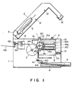
- Figure 1 is a sectional view of an image forming apparatus according to a first embodiment of the present invention, where it is opened in a first mode.
- Figure 2 is a sectional view of the image forming apparatus which is opened in a second mode.
- Figure 3 is a sectional view of the image forming apparatus which is opened in a third mode.
- Figure 4 is a front view illustrating engagement between a shaft and an engaging member in a holding mechanism.
- Figure 5 is a front view illustrating engagement between a shaft and an engaging member in a holding mechanism.
- Figure 6 is a sectional view of an image forming apparatus according to a second embodiment of the present invention.
- Figure 7 is a front sectional view of an image forming apparatus according to the second embodiment of the present invention.
- Figure 8 is a sectional view of an image forming apparatus according to a third embodiment of the present invention.
- Figure 9 is a sectional view of an image forming apparatus according to a fourth embodiment of the present invention.
- Figure 10 is a sectional view of an image forming apparatus according to the fourth embodiment of the present invention, which is opened in a first mode.
- Figure 11 is a side view of the image forming apparatus which is opened in a second mode.
- Figure 12 is a sectional view of the image forming apparatus which is opened in a third mode.
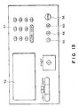
- Figure 13 shows an operation panel of an image forming apparatus according to an embodiment of the present invention.
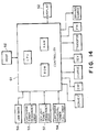
- Figure 14 is a block diagram of a control system of an image forming apparatus according to an embodiment of the present invention.
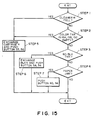
- Figure 15 is a flow chart showing a relation between a sensor and a display of an image forming apparatus according to an embodiment of the present invention.
- the image forming apparatus comprises a detachably mountable process cartridge having a plurality of developing means and a detachably mountable developing unit.
- the process cartridge may be different if it contains an image bearing member and at least one image forming means actable on the image bearing member.
- a main assembly 1 of a multi-color image forming apparatus comprises a lower frame (first casing) 1 and an upper frame (second casing) 2 which is rotatable relative to the lower frame about a shaft 3.
- the main assembly 1 accommodates a process cartridge 4 and a sub-cartridge (developing unit) 5, which are separately detachably mountable thereto.
- the sub-cartridge 5 is positioned relative to an image bearing member 10 in the main cartridge 4.
- the main cartridge 4 contains an image bearing member 10, three color developing devices 15 (15A, 15B and 15C) (image forming means) positioned relative to the image bearing member 10, a cleaner 16 (image forming means), a charger 50 (image forming means) or the like.
- the sub-cartridge 5 contains one color developing device 5A positioned relative to the image bearing member 10 of the main cartridge 4.
- the main assembly 1 contains a sheet feeding unit 6, an image transfer drum 7, an image fixing unit 8 and the like.
- the upper frame 2 is provided with a scanner unit 9.
- the image bearing member in the form of a photosensitive drum 10 is uniformly charged by the charger 50.
- light is projected from a scanner unit 9 onto the photosensitive member 10 in the main cartridge 4 in accordance with the color of the developer of the developing device 15A, so that an electrostatic latent image for the color is formed.
- the latent image on the photosensitive member is passed through a position where a developer carrying member (developing sleeve) 15a of the developing device 15A is opposed to the image bearing member.
- the developer (toner) carried on an outer periphery of the sleeve 15a is transferred onto the image bearing member 10 to develop the latent image into a visualized image.
- the latent image formation and the image development are repeated on the image bearing member in accordance with the selected developing device 15B, 15C and 5A.
- plural developed images are formed on the image bearing member 10 and they are simultaneously transferred onto a transfer material.
- the transfer material is subjected to an image fixing operation, and is discharged.
- the first color developed image is transferred onto a transfer material or an intermediate transfer member, and the latent image formation, development and transfer operation is repeated for the required colors.
- the transfer material is then subjected to an image fixing operation, and is discharged.
- the images are transferred onto an intermediate transfer member, the images are sequentially transferred from the intermediate transfer member onto the transfer material.
- the transfer material is subjected to an image fixing operation and is discharged.
- a developing bias is applied between the developer carrying member of the developing device and the image bearing member, the developer carrying member is rotated, and/or the distance between the developer carrying member and the image bearing member is reduced to a developable gap therebetween. By doing so, the developing action occurs.
- the image transfer of the developed image from the image bearing member onto the transfer material or onto the image transfer member is effected by electric force provided by the various voltage for moving the developer (developed image) of the image bearing member onto the transfer material and physical force due to the contact of the transfer member and the developer.
- an overlaid transfer system is used.
- the transfer sheet supplied from the sheet feeding unit 6 is retained on an outer periphery of the transfer drum 7, and the developed images of the colors are sequentially transferred from the image bearing member 10 onto the sheet.
- the sheet having received the transfer of the developed image is fed to an image fixing unit 8 after being separated from the transfer drum 7. Then, it is subjected to the image fixing operation and is discharged to the outside of the main assembly.
- a reference numeral 6 designates a sheet feeding unit for accommodating a transfer material or recording sheet S; 40, a pick-up roller for singling out the recording sheet S from the sheet feeding unit; 41, a registration roller; 42, a discharging roller; 43, a sheet discharging tray; 44, a guide; and 40, a transfer discharger.
- the main cartridge 4 is provided with two engaging members 11, and the sub-cartridge 5 is similarly provided with two engaging members 13.
- the upper frame 2 is provided with two shafts 12 and 14 extending in a direction perpendicular to the sheet of the drawing, which are rotatable.
- the shafts 12 and 14 are adapted to be engaged with the engaging members 11 and 13, respectively of the main cartridge 4 and the sub-cartridge 5.
- the engaging member 11 (13), as shown in detail in Figures 4 and 5, is provided with an engaging hole 11a (13a) and a groove 11b (13b) cut-away portion in the engaging hole 11a (13a).
- the apparatus can be opened with the cartridge 4 and the developing unit 5 placed in the frame which is different from the frame in the first mode (third mode). In this mode, a jammed sheet in the sheet feeding unit 6 or the transfer drum 7 can be easily removed, and the transfer drum 7 can be easily cleaned or serviced with good operativity.
- the first, second and third modes may be selected by a selector 55 shown in Figure 13.
- the apparatus of this invention is openable in a first mode in which the process cartridge and the developing unit are both in one of the first and second frames, and in a second mode in which the process cartridge and the developing unit are in the different frames.
- the maintenance operation such as jam clearance or cartridge or developing unit exchange, can be carried out without difficulty, despite the fact that plural elements are detachably mountable to the main assembly.
- a display means is provided to notify the operator of which mode is to be selected.
- a display 52 may be provided on the operation panel 51, as shown in Figure 13. The display sequence will be described in conjunction with a block diagram of Figure 14 and a flow chart of Figure 15.
- step 2 When a sensor (first detecting means) for detecting a remaining amount of the toner in the process cartridge detect toner empty (step 2), or when a residual toner sensor for detecting full of residual toner (third detecting means 54), detects a cleaner full (step 1), a display promoting the operator to exchange the cartridge 4 is displayed on the display 52 (step 5). Also displayed on the display 52 is the mode which the operator should select. Then, the operator depresses the switches 55 and 56 on the operation panel 51 to open the apparatus in the first mode, by which the second frame 2 is opened.
- the display 52 When a sensor for detecting the remaining amount of the toner in the developing unit 5 (second detecting means 57) detects toner empty (step 3), the display 52 promotes exchange of the developing unit 5 (step 6). Furthermore, the display 52 also displays that the second mode is to be selected by the operator. Then, the operator depresses the switches 58 and 56 to select the second mode on the operation panel 51, by which the second frame 2 is opened.
- the display 52 promotes the operator to open the apparatus in the third mode (step 7). Then, the operator depresses the switches 60 and 56 on the operation panel 51 to open the apparatus in the third mode, so that the second frame is opened in the third mode.
- the first, second and third modes are selected by selector switches 55, 58 and 60. It is further preferable that the first, second and third modes are automatically selected by a controller 61 in accordance with detection signals from the sensors 53, 54, 57 and 59.
- a controller 61 for controlling the entirety of the image forming apparatus comprises a CPU in the form of a microprocessor or the like, a ROM for storing control program or various data, and a RAM which is used as a work area of the CPU and which temporarily stores various data.
- the controller 61 receives signals from a sheet jam sensor 59 and a remaining toner detecting mechanism 53 for detecting the remaining amount of the toner in the process cartridge.
- the detecting mechanism may include an antenna line to detect the change of the electrostatic capacity between itself and the developing sleeve. Furthermore, it receives image signals from a host device 62 in the form of a computer or a word processor or the like.
- the controller 61 controls, the image exposure operation, charging operation, developing operation, image transfer operation, image fixing operation (process operations), conveyance of the recording material (registration roller, discharging roller or the like) and a driving source.
- Figure 6 is a side sectional view of a multi-color image forming apparatus according to this embodiment.
- Figure 7 is a front sectional view of the same.
- the same reference numerals as in Figures 1 - 3, are assigned to the elements having the corresponding functions, and the detailed description thereof are omitted for simplicity.
- the main cartridge 4 and the sub-cartridge 5 are provided with two projections 21 and 22, respectively.
- the upper frame 2 is provided with hooks 17 and 18 rotatable about respective shafts 19 and 20. End portions 17a and 18a of the hooks 17 and 18 are selectively engageable with the projections 21 and 22. They are provided with arms 17b and 18b which are crossed at the center of the shafts 19 and 20. To the crossing portions of the arms 17b and 18b, two members 23 and 24 guided in perpendicular directions, are contacted.
- the upper frame 2 is provided with a rotatable shaft 25 extending in a direction of the sheet of the drawing of Figure 6 (horizontal direction in Figure 7).
- a rotatable shaft 25 extending in a direction of the sheet of the drawing of Figure 6 (horizontal direction in Figure 7).
- two cams 26 and 27 are fixed, and the two cams are contactable to the members 23 and 24.
- a knob 28 is fixedly mounted to an end of the shaft 25.
- Each of the cams 26 and 27 has a large radius portion and a small radius portion. The cams 26 and 27 are rotatable by the knob 28.
- Figure 8 is a sectional view of a multi-color image forming apparatus according to this embodiment.
- the main cartridge 4 and/or the sub-cartridge 5 is raised together with the upper frame 2 by a selection and holding mechanism.
- a part 29 of the sheet feeding mechanism is raised together.
- the sub-cartridge 5 is fixed on a member 30 supporting the part 29 of the sheet feeding mechanism, so that it is raised by the upper frame 2 together with the member 30.
- the engaging member 13 ( Figure 1) and the projection 22 ( Figure 6) are provided in the sub-cartridge 5 itself, but it is provided on the member 30 in this embodiment.
- Figure 10 is a side sectional view of a multi-color image forming apparatus according to this embodiment.
- Figures 10 - 12 are side sectional views of the image forming apparatus in various modes.
- the upper frame 2 is provided with a frame 31 for holding the main cartridge 4 and a frame 32 for holding the sub-cartridge 5, and they are rotatable about a shaft 3.
- the upper frame 2 is provided with fixing members 33 and 34 for fixing the frames 31 and 32 to the upper frame 2, and the fixing members 33 and 34 are rotatable about shafts 35 and 36.
- the fixing members 33 and 34 are urged in the direction indicated by unshown springs.
- the apparatus is operable in a first mode in which the cartridge and the developing unit are located in the same frame (first or second), and in a second mode in which the cartridge and the developing unit are located separately in the first or second frames. Therefore, the jam clearance operation, the maintenance operation, exchanging operation of the cartridge or the developing unit, can be carried out without difficulty.
Landscapes
- Physics & Mathematics (AREA)
- General Physics & Mathematics (AREA)
- Engineering & Computer Science (AREA)
- Computer Vision & Pattern Recognition (AREA)
- Electrophotography Configuration And Component (AREA)
Applications Claiming Priority (2)
| Application Number | Priority Date | Filing Date | Title |
|---|---|---|---|
| JP26862891 | 1991-09-20 | ||
| JP268628/91 | 1991-09-20 |
Publications (3)
| Publication Number | Publication Date |
|---|---|
| EP0533484A2 true EP0533484A2 (de) | 1993-03-24 |
| EP0533484A3 EP0533484A3 (en) | 1993-07-07 |
| EP0533484B1 EP0533484B1 (de) | 1997-01-22 |
Family
ID=17461192
Family Applications (1)
| Application Number | Title | Priority Date | Filing Date |
|---|---|---|---|
| EP92308510A Expired - Lifetime EP0533484B1 (de) | 1991-09-20 | 1992-09-18 | Bilderzeugungsgerät |
Country Status (3)
| Country | Link |
|---|---|
| US (1) | US5323210A (de) |
| EP (1) | EP0533484B1 (de) |
| DE (1) | DE69216968D1 (de) |
Cited By (2)
| Publication number | Priority date | Publication date | Assignee | Title |
|---|---|---|---|---|
| EP1494095A1 (de) * | 2003-06-30 | 2005-01-05 | Ricoh Company, Ltd. | Bildaufzeichnungsvorrichtung |
| CN104516227A (zh) * | 2013-09-30 | 2015-04-15 | 兄弟工业株式会社 | 图像形成设备 |
Families Citing this family (15)
| Publication number | Priority date | Publication date | Assignee | Title |
|---|---|---|---|---|
| KR950006755B1 (ko) * | 1992-11-19 | 1995-06-22 | 삼성전자주식회사 | 정전기록방식 화상형성장치 |
| US5530504A (en) * | 1995-05-19 | 1996-06-25 | Eastman Kodak Company | Film cartridge ejector for photographic system |
| JP3432096B2 (ja) * | 1996-12-25 | 2003-07-28 | シャープ株式会社 | レーザー記録装置 |
| KR100246444B1 (ko) * | 1997-07-15 | 2000-03-15 | 윤종용 | 화상형성장치및방법 |
| JP3566507B2 (ja) * | 1997-08-01 | 2004-09-15 | キヤノン株式会社 | 電子写真画像形成装置 |
| JPH11153893A (ja) * | 1997-11-20 | 1999-06-08 | Fujitsu Ltd | 画像形成装置 |
| US6493528B2 (en) | 2000-03-03 | 2002-12-10 | Canon Kabushiki Kaisha | Image forming unit and image forming apparatus |
| US7162182B2 (en) * | 2004-03-19 | 2007-01-09 | Lexmark International, Inc. | Image forming device having a door assembly and method of use |
| US7136609B2 (en) * | 2004-03-19 | 2006-11-14 | Lexmark International, Inc. | Movable subunit and two piece cartridge for use in an image forming device |
| JP4875308B2 (ja) * | 2005-02-28 | 2012-02-15 | 株式会社沖データ | 画像記録装置 |
| US7639965B2 (en) * | 2006-04-19 | 2009-12-29 | Lexmark International, Inc. | Architecture for an image-forming device |
| US7675536B2 (en) * | 2006-04-19 | 2010-03-09 | Lexmark International, Inc. | Architectures for multi-functional image forming devices |
| JP4883353B2 (ja) * | 2006-09-08 | 2012-02-22 | 富士ゼロックス株式会社 | 画像形成装置 |
| JP5223210B2 (ja) * | 2007-03-09 | 2013-06-26 | ブラザー工業株式会社 | 画像形成装置 |
| US7986911B2 (en) | 2007-03-28 | 2011-07-26 | Lexmark International, Inc. | Architecture for a media feeding option for an image forming device |
Family Cites Families (14)
| Publication number | Priority date | Publication date | Assignee | Title |
|---|---|---|---|---|
| US4583844A (en) * | 1983-09-19 | 1986-04-22 | Konishiroku Photo Industry Co., Ltd. | Image recording apparatus with separable upper and lower sections and displaceable paper feed unit |
| JPS61279871A (ja) * | 1985-06-06 | 1986-12-10 | Canon Inc | 画像形成装置 |
| KR920001973B1 (ko) * | 1986-01-24 | 1992-03-07 | 도오꾜오 덴끼 가부시끼가이샤 | 정전 사진장치 |
| DE3850678T2 (de) * | 1987-01-09 | 1994-11-24 | Canon Kk | Arbeitseinheit und damit ausgestattetes Mehrfarben-Bilderzeugungsgerät. |
| US4928144A (en) * | 1987-05-31 | 1990-05-22 | Ricoh Kk | Developing device for a color image forming apparatus |
| JP2788285B2 (ja) * | 1988-09-12 | 1998-08-20 | 株式会社リコー | 画像記録装置 |
| US5036367A (en) * | 1988-11-07 | 1991-07-30 | Konica Corporation | Color image forming apparatus |
| CA2003398A1 (en) * | 1988-11-21 | 1990-05-21 | Shizuo Morita | Color copy machine with detachable process cartridge |
| JP2573047B2 (ja) * | 1988-12-06 | 1997-01-16 | コニカ株式会社 | カラー画像形成装置 |
| JPH02157870A (ja) * | 1988-12-12 | 1990-06-18 | Konica Corp | カラー画像形成装置 |
| JP2590015B2 (ja) * | 1989-02-15 | 1997-03-12 | 三田工業株式会社 | トナー像現像装置 |
| US5065195A (en) * | 1989-07-05 | 1991-11-12 | Konica Corporation | Color image forming apparatus having a freely installable and detachable process cartridge |
| JP2645670B2 (ja) * | 1990-01-19 | 1997-08-25 | キヤノン株式会社 | カラー画像形成装置 |
| US5235383A (en) * | 1990-08-31 | 1993-08-10 | Canon Kabushiki Kaisha | Process cartridge and image forming apparatus using same |
-
1992
- 1992-09-18 US US07/946,569 patent/US5323210A/en not_active Expired - Fee Related
- 1992-09-18 DE DE69216968T patent/DE69216968D1/de not_active Expired - Lifetime
- 1992-09-18 EP EP92308510A patent/EP0533484B1/de not_active Expired - Lifetime
Cited By (4)
| Publication number | Priority date | Publication date | Assignee | Title |
|---|---|---|---|---|
| EP1494095A1 (de) * | 2003-06-30 | 2005-01-05 | Ricoh Company, Ltd. | Bildaufzeichnungsvorrichtung |
| US7272342B2 (en) | 2003-06-30 | 2007-09-18 | Ricoh Co., Ltd. | Image forming apparatus having a detachable cartridge including a photoconductive drum with axis shaft having a minimal rotational eccentricity, and a method of assembling the image forming apparatus |
| CN104516227A (zh) * | 2013-09-30 | 2015-04-15 | 兄弟工业株式会社 | 图像形成设备 |
| CN104516227B (zh) * | 2013-09-30 | 2018-06-26 | 兄弟工业株式会社 | 图像形成设备 |
Also Published As
| Publication number | Publication date |
|---|---|
| DE69216968D1 (de) | 1997-03-06 |
| EP0533484B1 (de) | 1997-01-22 |
| EP0533484A3 (en) | 1993-07-07 |
| US5323210A (en) | 1994-06-21 |
Similar Documents
| Publication | Publication Date | Title |
|---|---|---|
| US5323210A (en) | Image forming apparatus featuring a multiple mode service access main assembly | |
| US8290395B2 (en) | Electrophotographic image forming apparatus | |
| US5182595A (en) | Image forming apparatus having an dismountable process cartridge | |
| JP3150187B2 (ja) | 画像形成装置 | |
| US5210573A (en) | Image forming apparatus | |
| US20130223853A1 (en) | Cartridge | |
| US12282284B2 (en) | Image forming apparatus having residual toner collecting containers | |
| JPH07306623A (ja) | 電子写真画像形成装置 | |
| EP0468750B1 (de) | Bilderzeugungsgerät | |
| US8472816B2 (en) | Process cartridge and image forming apparatus | |
| JP4191914B2 (ja) | 画像形成装置 | |
| JP3882528B2 (ja) | 画像形成装置 | |
| EP0503543A2 (de) | Bilderzeugungsgerät | |
| JPH10142940A (ja) | 現像装置 | |
| JPH09171338A (ja) | カラー画像形成装置 | |
| JP4277480B2 (ja) | 画像形成装置 | |
| JP4802683B2 (ja) | 画像形成装置 | |
| JP2005164727A (ja) | 画像形成装置 | |
| JPS60260968A (ja) | 現像装置 | |
| JPH08137175A (ja) | 画像形成装置 | |
| JPH05197228A (ja) | 画像形成装置 | |
| JP3251114B2 (ja) | 画像形成装置 | |
| JP4492603B2 (ja) | 画像形成装置 | |
| JPH04159564A (ja) | 画像形成装置 | |
| JP3142845B2 (ja) | カラー画像記録装置 |
Legal Events
| Date | Code | Title | Description |
|---|---|---|---|
| PUAI | Public reference made under article 153(3) epc to a published international application that has entered the european phase |
Free format text: ORIGINAL CODE: 0009012 |
|
| AK | Designated contracting states |
Kind code of ref document: A2 Designated state(s): DE FR GB IT |
|
| PUAL | Search report despatched |
Free format text: ORIGINAL CODE: 0009013 |
|
| AK | Designated contracting states |
Kind code of ref document: A3 Designated state(s): DE FR GB IT |
|
| 17P | Request for examination filed |
Effective date: 19931118 |
|
| 17Q | First examination report despatched |
Effective date: 19950207 |
|
| GRAG | Despatch of communication of intention to grant |
Free format text: ORIGINAL CODE: EPIDOS AGRA |
|
| GRAH | Despatch of communication of intention to grant a patent |
Free format text: ORIGINAL CODE: EPIDOS IGRA |
|
| GRAH | Despatch of communication of intention to grant a patent |
Free format text: ORIGINAL CODE: EPIDOS IGRA |
|
| GRAA | (expected) grant |
Free format text: ORIGINAL CODE: 0009210 |
|
| AK | Designated contracting states |
Kind code of ref document: B1 Designated state(s): DE FR GB IT |
|
| PG25 | Lapsed in a contracting state [announced via postgrant information from national office to epo] |
Ref country code: IT Free format text: LAPSE BECAUSE OF FAILURE TO SUBMIT A TRANSLATION OF THE DESCRIPTION OR TO PAY THE FEE WITHIN THE PRESCRIBED TIME-LIMIT;WARNING: LAPSES OF ITALIAN PATENTS WITH EFFECTIVE DATE BEFORE 2007 MAY HAVE OCCURRED AT ANY TIME BEFORE 2007. THE CORRECT EFFECTIVE DATE MAY BE DIFFERENT FROM THE ONE RECORDED. Effective date: 19970122 Ref country code: FR Effective date: 19970122 |
|
| REF | Corresponds to: |
Ref document number: 69216968 Country of ref document: DE Date of ref document: 19970306 |
|
| PG25 | Lapsed in a contracting state [announced via postgrant information from national office to epo] |
Ref country code: DE Effective date: 19970423 |
|
| EN | Fr: translation not filed | ||
| PLBE | No opposition filed within time limit |
Free format text: ORIGINAL CODE: 0009261 |
|
| 26N | No opposition filed | ||
| REG | Reference to a national code |
Ref country code: GB Ref legal event code: IF02 |
|
| PGFP | Annual fee paid to national office [announced via postgrant information from national office to epo] |
Ref country code: GB Payment date: 20050905 Year of fee payment: 14 |
|
| GBPC | Gb: european patent ceased through non-payment of renewal fee |
Effective date: 20060918 |
|
| PG25 | Lapsed in a contracting state [announced via postgrant information from national office to epo] |
Ref country code: GB Free format text: LAPSE BECAUSE OF NON-PAYMENT OF DUE FEES Effective date: 20060918 |