EP0533555B2 - Skelettprofil mit einer Zubehöranordnung - Google Patents
Skelettprofil mit einer Zubehöranordnung Download PDFInfo
- Publication number
- EP0533555B2 EP0533555B2 EP19920402527 EP92402527A EP0533555B2 EP 0533555 B2 EP0533555 B2 EP 0533555B2 EP 19920402527 EP19920402527 EP 19920402527 EP 92402527 A EP92402527 A EP 92402527A EP 0533555 B2 EP0533555 B2 EP 0533555B2
- Authority
- EP
- European Patent Office
- Prior art keywords
- shaped framework
- member according
- closure wall
- framework member
- support core
- Prior art date
- Legal status (The legal status is an assumption and is not a legal conclusion. Google has not performed a legal analysis and makes no representation as to the accuracy of the status listed.)
- Expired - Lifetime
Links
- 230000000295 complement effect Effects 0.000 claims description 7
- 230000001154 acute effect Effects 0.000 claims description 2
- 238000009432 framing Methods 0.000 claims description 2
- 239000007787 solid Substances 0.000 claims description 2
- 238000009434 installation Methods 0.000 description 6
- 238000005553 drilling Methods 0.000 description 5
- 238000011065 in-situ storage Methods 0.000 description 4
- 230000008901 benefit Effects 0.000 description 3
- 210000004027 cell Anatomy 0.000 description 3
- 238000002955 isolation Methods 0.000 description 2
- 238000007789 sealing Methods 0.000 description 2
- 240000008042 Zea mays Species 0.000 description 1
- 230000000903 blocking effect Effects 0.000 description 1
- 230000006835 compression Effects 0.000 description 1
- 238000007906 compression Methods 0.000 description 1
- 210000005069 ears Anatomy 0.000 description 1
- 230000005489 elastic deformation Effects 0.000 description 1
- 230000005484 gravity Effects 0.000 description 1
- 238000000034 method Methods 0.000 description 1
- 238000000465 moulding Methods 0.000 description 1
- 238000011084 recovery Methods 0.000 description 1
- 230000009897 systematic effect Effects 0.000 description 1
Images


Classifications
-
- E—FIXED CONSTRUCTIONS
- E05—LOCKS; KEYS; WINDOW OR DOOR FITTINGS; SAFES
- E05D—HINGES OR SUSPENSION DEVICES FOR DOORS, WINDOWS OR WINGS
- E05D5/00—Construction of single parts, e.g. the parts for attachment
- E05D5/02—Parts for attachment, e.g. flaps
- E05D5/0215—Parts for attachment, e.g. flaps for attachment to profile members or the like
- E05D5/0223—Parts for attachment, e.g. flaps for attachment to profile members or the like with parts, e.g. screws, extending through the profile wall or engaging profile grooves
- E05D5/023—Parts for attachment, e.g. flaps for attachment to profile members or the like with parts, e.g. screws, extending through the profile wall or engaging profile grooves with parts extending through the profile wall
-
- A—HUMAN NECESSITIES
- A47—FURNITURE; DOMESTIC ARTICLES OR APPLIANCES; COFFEE MILLS; SPICE MILLS; SUCTION CLEANERS IN GENERAL
- A47B—TABLES; DESKS; OFFICE FURNITURE; CABINETS; DRAWERS; GENERAL DETAILS OF FURNITURE
- A47B57/00—Cabinets, racks or shelf units, characterised by features for adjusting shelves or partitions
- A47B57/30—Cabinets, racks or shelf units, characterised by features for adjusting shelves or partitions with means for adjusting the height of detachable shelf supports
- A47B57/44—Cabinets, racks or shelf units, characterised by features for adjusting shelves or partitions with means for adjusting the height of detachable shelf supports consisting of screwbolts as connecting members
-
- A—HUMAN NECESSITIES
- A47—FURNITURE; DOMESTIC ARTICLES OR APPLIANCES; COFFEE MILLS; SPICE MILLS; SUCTION CLEANERS IN GENERAL
- A47B—TABLES; DESKS; OFFICE FURNITURE; CABINETS; DRAWERS; GENERAL DETAILS OF FURNITURE
- A47B96/00—Details of cabinets, racks or shelf units not covered by a single one of groups A47B43/00 - A47B95/00; General details of furniture
-
- H—ELECTRICITY
- H02—GENERATION; CONVERSION OR DISTRIBUTION OF ELECTRIC POWER
- H02B—BOARDS, SUBSTATIONS OR SWITCHING ARRANGEMENTS FOR THE SUPPLY OR DISTRIBUTION OF ELECTRIC POWER
- H02B1/00—Frameworks, boards, panels, desks, casings; Details of substations or switching arrangements
- H02B1/26—Casings; Parts thereof or accessories therefor
- H02B1/30—Cabinet-type casings; Parts thereof or accessories therefor
- H02B1/301—Cabinet-type casings; Parts thereof or accessories therefor mainly consisting of a frame onto which plates are mounted
-
- H—ELECTRICITY
- H05—ELECTRIC TECHNIQUES NOT OTHERWISE PROVIDED FOR
- H05K—PRINTED CIRCUITS; CASINGS OR CONSTRUCTIONAL DETAILS OF ELECTRIC APPARATUS; MANUFACTURE OF ASSEMBLAGES OF ELECTRICAL COMPONENTS
- H05K7/00—Constructional details common to different types of electric apparatus
- H05K7/18—Construction of rack or frame
- H05K7/183—Construction of rack or frame support rails therefor
-
- E—FIXED CONSTRUCTIONS
- E05—LOCKS; KEYS; WINDOW OR DOOR FITTINGS; SAFES
- E05Y—INDEXING SCHEME ASSOCIATED WITH SUBCLASSES E05D AND E05F, RELATING TO CONSTRUCTION ELEMENTS, ELECTRIC CONTROL, POWER SUPPLY, POWER SIGNAL OR TRANSMISSION, USER INTERFACES, MOUNTING OR COUPLING, DETAILS, ACCESSORIES, AUXILIARY OPERATIONS NOT OTHERWISE PROVIDED FOR, APPLICATION THEREOF
- E05Y2900/00—Application of doors, windows, wings or fittings thereof
- E05Y2900/20—Application of doors, windows, wings or fittings thereof for furniture, e.g. cabinets
-
- E—FIXED CONSTRUCTIONS
- E05—LOCKS; KEYS; WINDOW OR DOOR FITTINGS; SAFES
- E05Y—INDEXING SCHEME ASSOCIATED WITH SUBCLASSES E05D AND E05F, RELATING TO CONSTRUCTION ELEMENTS, ELECTRIC CONTROL, POWER SUPPLY, POWER SIGNAL OR TRANSMISSION, USER INTERFACES, MOUNTING OR COUPLING, DETAILS, ACCESSORIES, AUXILIARY OPERATIONS NOT OTHERWISE PROVIDED FOR, APPLICATION THEREOF
- E05Y2900/00—Application of doors, windows, wings or fittings thereof
- E05Y2900/20—Application of doors, windows, wings or fittings thereof for furniture, e.g. cabinets
- E05Y2900/208—Application of doors, windows, wings or fittings thereof for furniture, e.g. cabinets for metal cabinets
-
- H—ELECTRICITY
- H02—GENERATION; CONVERSION OR DISTRIBUTION OF ELECTRIC POWER
- H02B—BOARDS, SUBSTATIONS OR SWITCHING ARRANGEMENTS FOR THE SUPPLY OR DISTRIBUTION OF ELECTRIC POWER
- H02B1/00—Frameworks, boards, panels, desks, casings; Details of substations or switching arrangements
- H02B1/01—Frameworks
- H02B1/013—Profiles for cabinet frames
Definitions
- the present invention relates generally the profiles used for the constitution of a frame, in particular when such a frame is intended for the realization of a cabinet for apparatuses electric.
- this cabinet is a so-called assembled cabinet, i.e. a cabinet whose final assembly can if desired be carried out in situ.
- this covering is usually formed by a door, a bottom wall, two side walls, and a roof.
- the frame profile according to the invention is systematically equipped in advance in the workshop with several nuts, all of which are identical, duly staggered, in selected places, on its height.
- this implementation is all the more easy to do with a simple shouldered head axis, without the need to call on any tool.
- any frame profile 10 which, according to terms which, not pertaining to the present invention, will not be described here, is intended to constitute, with others, a framework, in particular that of a wardrobe for electrical equipment, and on a wall 11 of which, said here for the sake of convenience, must be brought back at least one accessory of equipment hereinafter designated by the general reference 12, namely, for example, with a view to functions explained later, a tip 12A, figure 13, a knuckle 12B, figure 15, a striker 12C, FIG. 19, a lock 12D, FIG. 21, or an assembly bracket 12E, figure 22.
- the frame profile 10 does not raise by itself of the present invention, and which may moreover fall of different achievements, it will not be described in all its details here.
- this profile of framework 10 comprises, overall, two wings 13, which generally extend at right angles to one another with respect to the other, jointly forming an edge 14 in front of the closure wall 11, and which each have a return 15 parallel to the other along their edge.
- the wings 13 also have each in hollow, between their edge 14 and their return 15, a recess 16, formed, in re-entrant angle, of two sides 18, 19, and the closure wall 11 globally connects them one to the other to the right of this offset 16, and, more precisely, in line with the edge 20 common to the two sides 18, 19 of it.
- Flaps 19 of the most distant recesses 16 of edge 14 are coplanar.
- the wall closure 11 has laterally parts of connection 22, which, framing its middle part 23, are oblique to it, this middle part 23 being offset transversely towards the edge 14, and, in practice, it belongs to a flange 24, which extends laterally both along the pan 19 of the recess 16 of the wings 13 furthest from the ridge 14 that along their return 15.
- the closing wall 11 comprises a set of two recesses 25, of outline quadrangular, which, lengthened in a parallel buttonhole to the direction of elongation D, affect each respectively its connecting parts 22, figure 2, by biting slightly on its middle part 23, with, between them, a bore 26, of circular outline.
- edge 29 of this recess 28 la further from edge 14 extends beyond the portion median 23 of the closing wall 11 relative to this edge 14, so that, thanks to the recesses 25 of the connecting parts 22 of the closure wall 11, it gives access to this middle part 23.
- the closure wall 11 of the profile frame 10 thus formed is equipped in advance at least one nut 32, which protrudes from the external surface of this closure wall 11, FIG. 5, is suitable for receive at least any accessories equipment 12.
- the closure wall 11 carries, by advance, at a distance from each other, several nuts 32, one per set of recesses 25.
- a nut 32 is in the general form of a relatively massive wafer, the main faces of which front 33 and rear 34 are parallel to the wall of closure 11, and more precisely at the middle part 23 of it, and whose upper and lower slices 36, not differentiated, extend parallel to one the other, perpendicular to the direction of elongation D.
- H be the height of the nut 32 measured from one of its upper and lower slices 36 to each other, in parallel to the direction of elongation D.
- the rear main face 34 forms the bearing face by which such a nut 32 is able to be leaned against the closure wall 11.
- the nut 32 comprises, over its entire thickness, i.e. perpendicularly to the rear main face 34 forming its bearing face, at least one hole 39, said below for convenience transverse drilling, in correspondence with the relevant bore 26 of the closure wall 11.
- this transverse drilling 39 is flared.
- the nut 32 extends laterally up to connecting parts 22 of the closure wall 11, FIGS. 5 and 6, and the means for locking in rotation associated with it result, in particular, from this that, for contact with these connection parts 22, it presents, laterally, in a complementary manner, on the rear main face 34 forming its bearing face, oblique facets 42.
- the slices sides of the nut 32 are each bevelled at the corner by two oblique facets 42 which extend globally parallel to the direction of elongation D.
- the nut 32 therefore has a profile by shuttle.
- These lugs 44 have, in section transverse, in the embodiment shown, a generally quadrangular outline, and in practice square, and their ends are flat.
- At least one of the faces lateral 46 which extend generally parallel to the direction of elongation D is also at an angle, converging towards the other from the root of this lug 44 to its end.
- the nut 32 comprises, over its entire height, parallel to the main face rear 34 forming its bearing face, and parallel to the direction of elongation D, at least one bore 50, says below for simple convenience, longitudinal drilling, suitable for the installation of a retaining member.
- the nut 32 thus has two holes parallel to each other longitudinal 50, which, each arranged respectively on either side of its transverse bore 39, are both at a distance from it.
- the nut 32 is engaged by its lugs 44 in the relevant recesses 25 of the closing wall 11 of the frame profile 10.
- the lugs 44 of the nut 32 thus ensure positioning and a precise centering of it with respect to to the frame profile 10.
- the transverse bore 39 of the nut 32 is located on the right of the corresponding bore 26 of the closure wall 11, and, because of its counterbore 48, it remains between it and the middle part 23 of this closure wall 11, a free space 52, figure 6.
- this free space 52 is used for the installation, on the middle part 23 of the closing wall 11, in favor of a part of the recess 25 of one of the connecting parts 22 thereof, and, on the other hand, the recess 28 wing 13 to which this connecting part 22 is adjacent, of a nut 53 of the type of those marketed under the name "RAPID”.
- the jamb 55 has a right foot 56, which is engaged in the tubular channel that define with the closing wall 11 the wings 13 of the frame profile 10, and that, for cooperation with the screw 38, this right foot 56 has transversely a tapped hole 58.
- each of the 32 intermediate nuts between the ends of the frame profile 10 are each individually directly attached to its wall closing 11.
- this equipment accessory 12 which it 12A tip, 12B knuckle, strike plate 12C, lock 12D or assembly bracket 12E, present two arms 60 by which it is able to be engaged, like a screed, on such a nut 32.
- these arms 60 which extend parallel to each other, are established at a distance From one of the other substantially equal to the height H of the nut 32, while being slightly higher than this.
- these arms 60 form ears.
- this retaining member 62 is a single axis with shoulder head 64.
- the tip 12A shown in Figure 13 constitutes a accessory of equipment, which, likely to be associated, according to the previously described provisions, at a frame profile 10, is capable of snapping onto it a side wall 70 of the cabinet concerned.
- this 12A tip has a hook 71.
- this hook 71 extends over the entire height of the middle part 72 connecting the arms to each other 60 correspondents.
- this tab elastically deformable 73 is in one piece with the tip 12A, coming from molding with it.
- this elastically deformable tongue 73 also extends over the entire height of the part median 72 of the end piece 12A, forming a dihedral with its hook 71.
- the side wall 70 which is equipped a gasket 74 for its contact with the return 15 of the corresponding wing 13 of the frame profile 10, has, beyond this seal 74, a flange 76 provided with a return 77, and this is assigned a notch 78 by which it is able to engage on the hook 71.
- the frame profile 10 being equipped with minus such a tip 12A, it suffices, the side wall 70 being suspended from the upper part of the corresponding framework, according to provisions not falling under the present invention, being initially separated from the profile of framework 10, as shown in solid lines on Figure 14A and as shown in broken lines in FIG. 18, to bring this side wall 70 closer to this frame profile 10, along arrow F1 of the figures 14A and 18, with concomitant compression of its seal sealing 74, until, as shown in solid line in Figure 14B and in Figure 18 it comes click into place, by the notch 78 of the return 77 of its rim 76, on the hook 71 of the end piece 12A, with a concomitant elastic deformation of the tongue elastically deformable 73 thereof.
- the knuckle 12B represented in FIG. 15 constitutes an equipment accessory which, associated with the frame profile 10, is suitable for the articulation of a door 80 to it, this door 80 being for this purpose equipped with a knuckle 81 complementary.
- the equipment accessory that constitutes the knuckle 12B has a wedge-shaped boss 83 which, in section transverse at least partly complementary to that of this dihedral 82, is capable of fitting into it.
- this boss 83 extends over the entire height of knuckle 128, to each other of the arms 60 thereof.
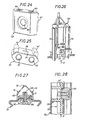
- the lock 12D shown in FIG. 20 constitutes an equipment accessory which, associated with the frame profile 10, allows, if desired, to open in the manner of a carries the bottom wall, not shown, of the cabinet concerned.
- the assembly bracket 12E shown in the figure 22 is suitable to participate, with another assembly stirrup 12E 'of the same type, to the subjection one to the other of two adjacent frame profiles 10, such as shown in Figure 23, especially for assembly two cabinets side by side.
- it comprises, connected one to the other in the form of a yoke by a middle part 92, two arms 60 with piercing 61, and, from one to the other of these arm 60, along the middle portion 92, a boss 83 wedge-shaped.
- the middle part 92 has transversely a drilling 93 for the passage of a screw 94.
- the middle part 92 On one side of this bore 93, the middle part 92 has a 95 stud protruding from its back, which, aligned of the hole 93, forms a cradle 96.
- the middle part 92 On the other side of the bore 93, the middle part 92 has a hollow 97 complementary to the tenon 95.
- boss 83 in wedge shape extends from one side to the middle 92; for assembly bracket 12E ', it extends from opposite side.
- stirrups 12E, 12E ' are associated back to back, by their middle part 92, with their bosses 83 shaped respective corner engaged with the corresponding 82 dihedrons of these frame profiles 10, and their arms 60 engaged on the nuts 32 of the same level thereof.
- the pins 95 form a conduit through their cradle 96, which, in the axis of their bore 93, is specific to the passage of wash 94.
- the tenons 95 provide guidance relative to each other of these two assembly brackets 12E, 12E '.
- each of the nuts 32 has projecting from its support face 34 as two lugs 44 ', which parallel to each other, and parallel to the direction of elongation D of the frame profiles 10 concerned, are elongated in this direction of elongation D.
- the face support 34 of a nut 32 is flat, the fixing being done no longer using a screw 38 intended to cooperate with a "RAPID" nut, but more directly by a 38 'rivet, for those of nuts 32 which are intermediate between the ends of the frame profiles 10.
Landscapes
- Engineering & Computer Science (AREA)
- Power Engineering (AREA)
- Microelectronics & Electronic Packaging (AREA)
- Mechanical Engineering (AREA)
- Casings For Electric Apparatus (AREA)
- Connection Of Plates (AREA)
- Furniture Connections (AREA)
Claims (33)
- Skelettprofil, insbesondere für einen Schrank für elektrische Geräte mit einer Wand (11), im nachstehenden der Einfachheit halber Verschlußwand genannt, auf der wenigstens ein beliebiges Ausrüstungszubehörteil (12) angebracht ist, dadurch gekennzeichnet, daß seine Verschlußwand (11) im Werk im voraus mit wenigstens einer Nuß (32) ausgerüstet ist, die von dem Ausrüstungszubehörteil (12) getrennt ist, an der Verschlußwand (11) hervorsteht und dieses Ausrüstungszubehörteil (12) aufnimmt, wobei jedes solche Ausrüstungszubehörteil unter verschiedenen Ausrüstungszubehörteilen (12A, 12B, 12C, 12D, 12E) ausgewählt ist, die alle Mittel (60) zur Befestigung an der Nuß (32) aufweisen, so daß die Nuß dieses unterschiedslos aufnehmen kann.
- Skelettprofil nach Anspruch 1, dadurch gekennzeichnet, daß die Nuß (32) für den Durchgang eines zu ihrer Befestigung dienenden Befestigungsorgans (38, 38') auf ihrer ganzen Dicke senkrecht zu der Auflagefläche (34), mit der sie an der Verschlußwand (11) anliegen kann, wenigstens eine Bohrung (39), im nachstehenden der Einfachheit halber Querbohrung genannt, aufweist und die Verschlußwand (11) ihrerseits in Übereinstimmung eine Bohrung (26) aufweist.
- Skelettprofil nach Anspruch 2, dadurch gekennzeichnet, daß die Nuß (32) nur eine Querbohrung (39) aufweist und daß ihr Mittel zur Blockierung bezüglich Drehung zugeordnet sind, die ihren Halt um die Achse dieser Querbohrung (39) gewährleisten können.
- Skelettprofil nach Anspruch 3, dadurch gekennzeichnet, daß, indem die Verschlußwand (11) seitlich Verbindungsteile (22) besitzt, die ihren mittleren Teil (23) säumen und zu diesem schräg sind, die Nuß (32) sich seitlich bis zu diesen Verbindungsteilen (22) der Verschlußwand (11) erstreckt und die ihr zugeordneten Mittel zur Blockierung bezüglich Drehung sich insbesondere daraus ergeben, daß sie für den Kontakt mit diesen seitlich ergänzend auf der Auflagefläche (34), mit der sie an der Verschlußwand (11) anliegen kann, schräge Facetten (42) aufweist.
- Skelettprofil nach einem der Ansprüche 1 bis 4, dadurch gekennzeichnet, daß die Nuß (32) wenigstens eine Nase (44, 44') besitzt, die auf der Auflagefläche (34), mit der sie an der Verschlußwand (11) anliegen kann, hervorsteht, und die Verschlußwand (11) ihrerseits in Entsprechung zur Einführung dieser Nase eine Aussparung (25) besitzt.
- Skelettprofil nach Anspruch 5, dadurch gekennzeichnet, daß die Nuß (32) vier auf der Auflagefläche (34) hervorstehende Nasen (44) besitzt, deren jede jeweilig an den Ecken eines rechtwinkeligen Vierecks angeordnet ist, von dem zwei Seiten zur Längserstreckungsrichtung (D) der Einheit parallel sind, und daß die Verschlußwand (11) in Entsprechung seitlich zwei Aussparungen (25) mit rechtwinkeligem Umriß besitzt, die in Form eines Langlochs parallel zur Längserstreckungsrichtung (D) langgestreckt sind.
- Skelettprofil nach Anspruch 6, dadurch gekennzeichnet, daß diejenigen (45) der Seitenflächen der Nasen (44), die sich insbesondere quer zur Längserstreckungsrichtung (D) der Einheit erstrecken, abgeschrägt sind, indem sie bei ein und derselben Nase von der Wurzel dieser Nase zu ihrem Ende aufeinander zu konvergieren.
- Skelettprofil nach einem der Ansprüche 6, 7, dadurch gekennzeichnet, daß bei ein und derselben Nase (44) wenigstens eine der Seitenflächen (46), die sich insbesondere parallel zur Längserstreckungsrichtung (D) der Einheit erstrecken, abgeschrägt ist, indem sie von der Wurzel dieser Nase (44) zu ihrem Ende auf die andere zu konvergiert.
- Skelettprofil nach Anspruch 5, dadurch gekennzeichnet, daß die Nuß (32) auf ihrer Auflagefläche (34) vorspringend zwei zueinander und zur Längserstrekkungsrichtung (D) parallele Nasen (44') besitzt, die in dieser Längserstreckungsrichtung (D) langgestreckt sind, und die Verschlußwand (11) in Entsprechung seitlich zwei Aussparungen (25) mit rechtwinkeligem Umriß besitzt, die in Form eines Langlochs parallel zu dieser Längserstreckungsrichtung (D) langgestreckt sind.
- Skelettprofil nach einem der Ansprüche 6, 9 zusammen mit Anspruch 4, dadurch gekennzeichnet, daß die Aussparungen (25) der Verschlußwand (11) sich auf ihren Verbindungsteilen (22) erstrecken, indem sie leicht auf ihren Mittelteil (23) übergreifen.
- Skelettprofil nach einem der Ansprüche 1 bis 10, dadurch gekennzeichnet, daß die Auflagefläche (34), die die Nuß (32) besitzt, um an die Verschlußwand (11) angelegt zu werden, in Querrichtung auf ihrer ganzen Breite mit einer Einsenkung (48) versehen ist.
- Skelettprofil nach einem der Ansprüche 1 bis 11, dadurch gekennzeichnet, daß die Nuß (32) zur Anbringung eines Ausrüstungszubehörteils (12) an ihr auf ihrer ganzen Höhe parallel zur Auflagefläche (34), mit der sie an die Verschlußwand angelegt werden kann, und parallel zur Längserstreckungsrichtung (D) der Einheit wenigstens eine Bohrung (50) umfaßt, der Einfachheit halber Längsbohrung genannt, die für die Anbringung eines Halteorgans (62) geeignet ist.
- Skelettprofil nach Anspruch 12, dadurch gekennzeichnet, daß die Nuß (32) parallel zueinander zwei Längsbohrungen (50) aufweist.
- Skelettprofil nach einem der Ansprüche 1 bis 13, dadurch gekennzeichnet, daß die Nuß (32) die Form einer massiven Plakette hat, deren Hauptseiten (33, 34) zur Verschlußwand (11) parallel sind und deren obere und untere Schmalseiten (36) sich parallel zueinander und senkrecht zur Längserstreckungsrichtung (D) der Einheit erstrecken.
- Skelettprofil nach Anspruch 14, dadurch gekennzeichnet, daß die seitlichen Schmalseiten der Nuß (32) jeweils keilförmig durch zwei schräge Facetten (42) abgeschrägt sind, die sich global parallel zur Längserstreckungsrichtung (D) der Einheit erstrecken.
- Skelettprofil nach einem der Ansprüche 1 bis 15, dadurch gekennzeichnet, daß, indem die Verschlußwand (11) zwei Schenkel (13) miteinander verbindet, die sich global rechtwinkelig zueinander erstrecken und zusammen bezüglich der Verschlußwand (11) nach vorne eine Kante (14) bilden, wenigstens einer der Schenkel (13) eine Aussparung (28) für den Durchgang einer Mutter (53) besitzt.
- Skelettprofil nach den Ansprüchen 6 und 16 zusammen, dadurch gekennzeichnet, daß die Aussparung (28) eines Schenkels (13) sich in der Höhe einer Aussparung (25) der Verschlußwand (11) erstreckt.
- Skelettprofil nach einem der Ansprüche 1 bis 17, dadurch gekennzeichnet, daß seine Verschlußwand von vornherein in einem Abstand voneinander mehrere Nüsse (32) trägt.
- Skelettprofil nach Anspruch 18, dadurch gekennzeichnet, daß die Nüsse (32), die seinen Enden am nächsten gelegen sind, an der Befestigung von Füßen (55) an diesen teilnehmen.
- Skelettprofil nach Anspruch 18, dadurch gekennzeichnet, daß die zwischen seinen Enden gelegenen Nüsse (32) jeweils einzeln an seiner Verschlußwand (11) angebracht sind.
- Skelettprofil nach einem der Ansprüche 18 bis 20, dadurch gekennzeichnet, daß die Nüsse (32), die seine Verschlußwand (11) trägt, alle untereinander identisch sind.
- Skelettprofil nach einem der Ansprüche 1 bis 21, dadurch gekennzeichnet, daß jedes Ausrüstungszubehörteil (12), das ihm zugeordnet ist, zwei Arme (60) besitzt, mit denen es nach der Art einer Gabel auf eine von seiner Verschlußwand (11) getragene Nuß (32) aufgesteckt werden kann.
- Skelettprofil nach den Ansprüchen 12 und 22 zusammen, dadurch gekennzeichnet, daß die Arme (60) des Ausrüstungszubehörteils (12) jeweils eine Bohrung für den Durchgang eines Halteorgans (62) besitzen.
- Skelettprofil nach Anspruch 23, dadurch gekennzeichnet, daß das Halteorgan (62) eine einfache Achse mit abgesetztem Kopf (64) ist.
- Skelettprofil nach einem der Ansprüche 23, 24, dadurch gekennzeichnet, daß die Bohrung (61), die der obere Arm (60) des Ausrüstungszubehörteils (12) besitzt, an seiner oberen Mündung eine Ausnehmung (65) bildet, in die der abgesetzte Kopf (64) der das Halteorgan (62) bildenden Achse eingelassen werden kann und die seitlich über eine Aussparung (66) ausmündet.
- Skelettprofil nach einem der Ansprüche 1 bis 25, dadurch gekennzeichnet, daß ihn als an seiner Verschlußwand (11) anzubringendes Ausrüstungszubehörteil (12) wenigstens ein Aufsatz (12A) zugeordnet ist, der mit einem Haken (71) versehen ist und die Einklinkung einer seitlichen Wand (70) des betreffenden Schranks gestattet.
- Skelettprofil nach Anspruch 26, dadurch gekennzeichnet, daß dieser Aufsatz (12A) für die Auflage auf dem Skelettprofilteil eine elastisch verformbare Zunge (73) besitzt.
- Skelettprofil nach einem der Ansprüche 1 bis 27, dadurch gekennzeichnet, daß ihm als an seiner Verschlußwand (11) anzubringendes Ausrüstungszubehörteil (12) wenigstens ein Scharnier (12B) zugeordnet ist, das die Anlenkung einer Tür (80) oder einer beliebigen anderen Wand gestattet.
- Skelettprofil nach einem der Ansprüche 1 bis 28, dadurch gekennzeichnet, daß ihm als an seiner Verschlußwand (11) anzubringendes Ausrüstungszubehörteil (12) wenigstens ein Schließorgan (12C) zugeordnet ist.
- Skelettprofil nach einem der Ansprüche 1 bis 29, dadurch gekennzeichnet, daß ihm als an seiner Verschlußwand (11) anzubringendes Ausrüstungszubehörteil (12) wenigstens ein Riegel (12D) zugeordnet ist.
- Skelettprofil nach einem der Ansprüche 1 bis 30, dadurch gekennzeichnet, daß ihm als an seiner Verschlußwand (11) anzubringendes Ausrüstungszubehörteil (12) wenigstens ein Montagebügel (12E) zugeordnet ist, der zusammen mit einem Montagebügel (12E') vom selben Typ geeignet ist, an der gegenseitigen Befestigung von zwei benachbarten Skelettprofilen teilzunehmen.
- Skelettprofil nach Anspruch 31, dadurch gekennzeichnet, daß der mittlere Teil (92) eines Montagebügels (12E, 12E') einerseits eine an seinem Rücken hervorstehende Nase (95), die mit einer Bohrung (93) in einer Linie liegt und ein Lager (96) für den Durchgang einer Schraube (94) bildet, und andererseits eine Aussparung (97) besitzt, die zur Nase (95) komplementär ist.
- Skelettprofil nach einem der Ansprüche 28 bis 32, dadurch gekennzeichnet, daß, wenn seine Verschlußwand (11) zwei Schenkel (13) miteinander verbindet, die längs ihres Randes jeweils eine Abwinklung (15) aufweisen, die mit ihrem unmittelbar benachbarten Teil einen die Dieder (82) mit spitzem Winkel (A) bildet, das ihm zugeordnete Ausrüstungszubehörteil (12B, 12C) eine keilförmige Erhebung (63) besitzt, deren Querschnitt wenigstens teilweise zu dem eines solchen Dieders (82) komplementär ist und die in diesen eingelassen werden kann.
Applications Claiming Priority (2)
| Application Number | Priority Date | Filing Date | Title |
|---|---|---|---|
| FR9111483A FR2681404B1 (fr) | 1991-09-18 | 1991-09-18 | Profile d'ossature sur lequel doit etre rapporte un accessoire d'equipement, et accessoires d'equipement susceptibles d'etre associes a un tel profile d'ossature. |
| FR9111483 | 1991-09-18 |
Publications (3)
| Publication Number | Publication Date |
|---|---|
| EP0533555A1 EP0533555A1 (de) | 1993-03-24 |
| EP0533555B1 EP0533555B1 (de) | 1996-03-13 |
| EP0533555B2 true EP0533555B2 (de) | 2001-08-22 |
Family
ID=9417051
Family Applications (1)
| Application Number | Title | Priority Date | Filing Date |
|---|---|---|---|
| EP19920402527 Expired - Lifetime EP0533555B2 (de) | 1991-09-18 | 1992-09-16 | Skelettprofil mit einer Zubehöranordnung |
Country Status (4)
| Country | Link |
|---|---|
| EP (1) | EP0533555B2 (de) |
| DE (2) | DE533555T1 (de) |
| ES (1) | ES2039322T5 (de) |
| FR (1) | FR2681404B1 (de) |
Families Citing this family (17)
| Publication number | Priority date | Publication date | Assignee | Title |
|---|---|---|---|---|
| DE4336188C2 (de) * | 1993-10-23 | 1996-10-24 | Loh Kg Rittal Werk | Schaltschrank mit Rahmengestell und Türelementen |
| DE4336204C2 (de) * | 1993-10-23 | 1996-11-07 | Loh Kg Rittal Werk | Rahmengestell für einen Schaltschrank |
| DE19506744C1 (de) * | 1995-02-27 | 1996-04-18 | Loh Kg Rittal Werk | Schaltschrank mit Rahmengestell und Türelementen |
| DE19647803C1 (de) * | 1996-11-19 | 1998-03-05 | Loh Kg Rittal Werk | Schaltschrank mit einem Rahmengestell |
| DE29623551U1 (de) * | 1996-11-19 | 1998-10-01 | Rittal-Werk Rudolf Loh GmbH & Co. KG, 35745 Herborn | Schaltschrank |
| IT1291616B1 (it) * | 1997-04-18 | 1999-01-11 | Abb Turati S P A | Intelaiatura con dispositivo di collegamento e di supporto per profilati e pannelli di armadi |
| DE19735251C1 (de) * | 1997-08-14 | 1999-02-11 | Loh Kg Rittal Werk | Vorrichtung zum Verbinden von anreihbaren Schaltschränken |
| DE19814268C1 (de) * | 1998-03-31 | 1999-11-25 | Loh Kg Rittal Werk | Vorrichtung zum Befestigen von Anbauelementen an einem Rahmenschenkel eines Schaltschrank-Rahmengestelles |
| DE19817209A1 (de) * | 1998-04-17 | 1999-10-28 | Skeppner Hans | Rahmengestell für einen Schaltschrank |
| DE10113924C1 (de) * | 2001-03-21 | 2002-07-18 | Rittal Rcs Comm Systems Gmbh & Co Kg | Beschlagteile zum Befestigen an Rahmenschenkeln eines Schaltschrank-Rahmengestelles |
| DE10136681C2 (de) * | 2001-07-27 | 2003-10-02 | Eldon Holding Ab Rijswijk | Rahmengestell |
| DE10328402B4 (de) * | 2003-06-25 | 2016-10-13 | Abb Ag | Schaltschrank |
| DE10328403A1 (de) * | 2003-06-25 | 2005-01-13 | Abb Patent Gmbh | Befestigungsbock |
| DE10338337A1 (de) * | 2003-08-21 | 2005-03-31 | Abb Patent Gmbh | Befestigungsbock |
| FR2912002B1 (fr) | 2007-01-26 | 2009-08-07 | Legrand France | Armoire pour appareils electriques comportant une ossature presentant au moins un montant profile et un support d'equipement |
| FR2919763B1 (fr) * | 2007-08-01 | 2009-10-30 | Legrand France | Dispositif pour relier deux armoires pour appareils electriques |
| KR101045187B1 (ko) * | 2008-12-04 | 2011-06-28 | 엘에스산전 주식회사 | 스위치기어 외함용 프레임 |
Family Cites Families (3)
| Publication number | Priority date | Publication date | Assignee | Title |
|---|---|---|---|---|
| FR2648005B1 (fr) * | 1989-06-05 | 1993-11-26 | Merlin Gerin | Armoire etanche d'appareillage electrique |
| US4958439A (en) * | 1989-11-30 | 1990-09-25 | Dehn Freddie H | Method and device for aligning vehicle frame |
| DE4013381C1 (en) * | 1990-04-26 | 1991-07-18 | Rittal-Werk Rudolf Loh Gmbh & Co Kg, 6348 Herborn, De | Electrical equipment cabinet with mounting frame - with U=shaped transverse bars for dividing into compartments |
-
1991
- 1991-09-18 FR FR9111483A patent/FR2681404B1/fr not_active Expired - Fee Related
-
1992
- 1992-09-16 DE DE1992402527 patent/DE533555T1/de active Pending
- 1992-09-16 DE DE1992608989 patent/DE69208989T3/de not_active Expired - Fee Related
- 1992-09-16 EP EP19920402527 patent/EP0533555B2/de not_active Expired - Lifetime
- 1992-09-16 ES ES92402527T patent/ES2039322T5/es not_active Expired - Lifetime
Also Published As
| Publication number | Publication date |
|---|---|
| EP0533555B1 (de) | 1996-03-13 |
| FR2681404B1 (fr) | 1993-12-10 |
| EP0533555A1 (de) | 1993-03-24 |
| ES2039322T1 (es) | 1993-10-01 |
| DE69208989T2 (de) | 1996-07-25 |
| FR2681404A1 (fr) | 1993-03-19 |
| DE69208989T3 (de) | 2001-11-22 |
| ES2039322T3 (es) | 1996-10-01 |
| DE533555T1 (de) | 1993-07-08 |
| ES2039322T5 (es) | 2001-10-16 |
| DE69208989D1 (de) | 1996-04-18 |
Similar Documents
| Publication | Publication Date | Title |
|---|---|---|
| EP0533555B2 (de) | Skelettprofil mit einer Zubehöranordnung | |
| FR2595513A1 (fr) | Support adaptateur pour appareillage electrique | |
| EP0936711B1 (de) | Verkapselung, insbesondere Kasten für elektrische Geräte | |
| EP1189323B1 (de) | Vorrichtung zur Befestigung eines eingebauten elektrischen Gerätes in einen Kabelkanal mit einer kleineren Tiefe | |
| EP0845563B1 (de) | Griff für öffnungsfähigen Flügel, und Schrank wovon die Tür mit einem derartigen Griff ausgerüstet ist | |
| EP0702120B1 (de) | Bodenelement für Gerüstboden | |
| EP0851551B1 (de) | Verfahren und Vorrichtung zum Verbessern des Haltens eines Zubehörs mit Schnappbefestigung an einem Kabelrinnensockel | |
| EP0504044B1 (de) | Schrank mit verriegelbarer und umwendbarer Tür, und ein System mit einem solchen Schrank | |
| EP0762586B1 (de) | Gehäuse für elektrische Geräte | |
| FR2681403A1 (fr) | Dispositif d'assemblage pour profiles d'ossature, ossature correspondante, et armoire, en particulier armoire pour appareillages electriques, mettant en óoeuvre une telle ossature. | |
| EP0989647B1 (de) | Rahmengestell, insbesondere für ein Elektrogerät | |
| EP0940349B1 (de) | Dose bestehend aus lösbaren, schwenkbaren Elementen, insbesondere für Leuchten | |
| FR2917911A1 (fr) | Coffret destine a recevoir un appareillage electrique | |
| EP0267079B1 (de) | Abzweigungszubehör für Verkabelungsrohr | |
| EP0762585A1 (de) | Befestigungszubehör zur Montage an ein Gestell, insbesondere für Befestigung von elektrischen Apparaten | |
| EP0440556A1 (de) | Einbaudose mit Seitenverlängerung, insbesondere für elektrisches Gerät | |
| EP1022833B1 (de) | Adapter für einen Mechanismusträger, und Mechanismusträger mit einem solchen Adapter, inbesondere für ein Elektrogerät | |
| EP0829650A1 (de) | Befestigungsvorrichtung für Blöcke, insbesondere zur Befestigung eines autonomen Notbeleuchtungsblockes auf einem Träger | |
| EP2623694B1 (de) | Einheit zur Herstellung von elektromagnetischen Bändern verschiedener Höhe | |
| EP1013833A1 (de) | Verriegelungsanordnung einer Zugangsklappe zu unterirdischen Bauwerken | |
| EP4455429B1 (de) | Sicht- oder verdunkelungspaneel für starre gitterzäune und befestigungsverfahren dafür | |
| EP0263754A1 (de) | Dichter Schrank mit einem Schutzdachrand, insbesondere für elektrische Geräte | |
| FR2811696A1 (fr) | Ferrure de verrouillage d'ouvrant a mors d'appui interieur manoeuvrable en translation, procede de montage et ouvrant equipe d'une telle ferrure | |
| FR2781616A1 (fr) | Boite d'encastrement susceptible d'etre jumelee avec une autre, notamment pour appareillage electrique | |
| FR2695763A1 (fr) | Accessoire de support pour coffret, notamment pour appareillages électriques. |
Legal Events
| Date | Code | Title | Description |
|---|---|---|---|
| PUAI | Public reference made under article 153(3) epc to a published international application that has entered the european phase |
Free format text: ORIGINAL CODE: 0009012 |
|
| AK | Designated contracting states |
Kind code of ref document: A1 Designated state(s): DE ES FR GB IT SE |
|
| ITCL | It: translation for ep claims filed |
Representative=s name: FUMERO BREVETTI S.N.C. |
|
| GBC | Gb: translation of claims filed (gb section 78(7)/1977) | ||
| 17P | Request for examination filed |
Effective date: 19930419 |
|
| DET | De: translation of patent claims | ||
| 17Q | First examination report despatched |
Effective date: 19950116 |
|
| GRAA | (expected) grant |
Free format text: ORIGINAL CODE: 0009210 |
|
| AK | Designated contracting states |
Kind code of ref document: B1 Designated state(s): DE ES FR GB IT SE |
|
| REG | Reference to a national code |
Ref country code: ES Ref legal event code: BA2A Ref document number: 2039322 Country of ref document: ES Kind code of ref document: T3 |
|
| ITF | It: translation for a ep patent filed | ||
| REF | Corresponds to: |
Ref document number: 69208989 Country of ref document: DE Date of ref document: 19960418 |
|
| GBT | Gb: translation of ep patent filed (gb section 77(6)(a)/1977) |
Effective date: 19960328 |
|
| REG | Reference to a national code |
Ref country code: ES Ref legal event code: FG2A Ref document number: 2039322 Country of ref document: ES Kind code of ref document: T3 |
|
| REG | Reference to a national code |
Ref country code: ES Ref legal event code: FG2A Ref document number: 2039322 Country of ref document: ES Kind code of ref document: T3 |
|
| PLBQ | Unpublished change to opponent data |
Free format text: ORIGINAL CODE: EPIDOS OPPO |
|
| PLBI | Opposition filed |
Free format text: ORIGINAL CODE: 0009260 |
|
| 26 | Opposition filed |
Opponent name: RITTAL-WERK RUDOLF LOH GMBH & CO. KG Effective date: 19961213 |
|
| PLBF | Reply of patent proprietor to notice(s) of opposition |
Free format text: ORIGINAL CODE: EPIDOS OBSO |
|
| PLBF | Reply of patent proprietor to notice(s) of opposition |
Free format text: ORIGINAL CODE: EPIDOS OBSO |
|
| PLAW | Interlocutory decision in opposition |
Free format text: ORIGINAL CODE: EPIDOS IDOP |
|
| PLAW | Interlocutory decision in opposition |
Free format text: ORIGINAL CODE: EPIDOS IDOP |
|
| PUAH | Patent maintained in amended form |
Free format text: ORIGINAL CODE: 0009272 |
|
| STAA | Information on the status of an ep patent application or granted ep patent |
Free format text: STATUS: PATENT MAINTAINED AS AMENDED |
|
| 27A | Patent maintained in amended form |
Effective date: 20010822 |
|
| AK | Designated contracting states |
Kind code of ref document: B2 Designated state(s): DE ES FR GB IT SE |
|
| GBTA | Gb: translation of amended ep patent filed (gb section 77(6)(b)/1977) | ||
| ITF | It: translation for a ep patent filed | ||
| REG | Reference to a national code |
Ref country code: ES Ref legal event code: DC2A Kind code of ref document: T5 Effective date: 20010828 |
|
| REG | Reference to a national code |
Ref country code: GB Ref legal event code: IF02 |
|
| REG | Reference to a national code |
Ref country code: FR Ref legal event code: CD |
|
| REG | Reference to a national code |
Ref country code: ES Ref legal event code: PC2A |
|
| PGFP | Annual fee paid to national office [announced via postgrant information from national office to epo] |
Ref country code: ES Payment date: 20070920 Year of fee payment: 16 |
|
| PGFP | Annual fee paid to national office [announced via postgrant information from national office to epo] |
Ref country code: GB Payment date: 20070914 Year of fee payment: 16 |
|
| PGFP | Annual fee paid to national office [announced via postgrant information from national office to epo] |
Ref country code: SE Payment date: 20070820 Year of fee payment: 16 |
|
| PLAB | Opposition data, opponent's data or that of the opponent's representative modified |
Free format text: ORIGINAL CODE: 0009299OPPO |
|
| PGFP | Annual fee paid to national office [announced via postgrant information from national office to epo] |
Ref country code: IT Payment date: 20080918 Year of fee payment: 17 |
|
| PGFP | Annual fee paid to national office [announced via postgrant information from national office to epo] |
Ref country code: DE Payment date: 20080911 Year of fee payment: 17 |
|
| PGFP | Annual fee paid to national office [announced via postgrant information from national office to epo] |
Ref country code: FR Payment date: 20080925 Year of fee payment: 17 |
|
| GBPC | Gb: european patent ceased through non-payment of renewal fee |
Effective date: 20080916 |
|
| REG | Reference to a national code |
Ref country code: ES Ref legal event code: FD2A Effective date: 20080917 |
|
| PG25 | Lapsed in a contracting state [announced via postgrant information from national office to epo] |
Ref country code: GB Free format text: LAPSE BECAUSE OF NON-PAYMENT OF DUE FEES Effective date: 20080916 |
|
| PG25 | Lapsed in a contracting state [announced via postgrant information from national office to epo] |
Ref country code: ES Free format text: LAPSE BECAUSE OF NON-PAYMENT OF DUE FEES Effective date: 20080917 |
|
| PG25 | Lapsed in a contracting state [announced via postgrant information from national office to epo] |
Ref country code: SE Free format text: LAPSE BECAUSE OF NON-PAYMENT OF DUE FEES Effective date: 20080917 Ref country code: DE Free format text: LAPSE BECAUSE OF NON-PAYMENT OF DUE FEES Effective date: 20100401 |
|
| PG25 | Lapsed in a contracting state [announced via postgrant information from national office to epo] |
Ref country code: IT Free format text: LAPSE BECAUSE OF NON-PAYMENT OF DUE FEES Effective date: 20090916 |
|
| REG | Reference to a national code |
Ref country code: FR Ref legal event code: ST Effective date: 20110729 |
|
| PG25 | Lapsed in a contracting state [announced via postgrant information from national office to epo] |
Ref country code: FR Free format text: LAPSE BECAUSE OF NON-PAYMENT OF DUE FEES Effective date: 20090930 |