EP0534775A1 - Thermistance - Google Patents
Thermistance Download PDFInfo
- Publication number
- EP0534775A1 EP0534775A1 EP92308746A EP92308746A EP0534775A1 EP 0534775 A1 EP0534775 A1 EP 0534775A1 EP 92308746 A EP92308746 A EP 92308746A EP 92308746 A EP92308746 A EP 92308746A EP 0534775 A1 EP0534775 A1 EP 0534775A1
- Authority
- EP
- European Patent Office
- Prior art keywords
- ptc
- bodies
- ptc thermistor
- thermistor device
- thermistor
- Prior art date
- Legal status (The legal status is an assumption and is not a legal conclusion. Google has not performed a legal analysis and makes no representation as to the accuracy of the status listed.)
- Withdrawn
Links
Images
Classifications
-
- H—ELECTRICITY
- H01—ELECTRIC ELEMENTS
- H01C—RESISTORS
- H01C13/00—Resistors not provided for elsewhere
- H01C13/02—Structural combinations of resistors
-
- H—ELECTRICITY
- H01—ELECTRIC ELEMENTS
- H01C—RESISTORS
- H01C1/00—Details
- H01C1/14—Terminals or tapping points specially adapted for resistors; Arrangements of terminals or tapping points on resistors
- H01C1/1406—Terminals or electrodes formed on resistive elements having positive temperature coefficient
-
- H—ELECTRICITY
- H01—ELECTRIC ELEMENTS
- H01C—RESISTORS
- H01C7/00—Non-adjustable resistors formed as one or more layers or coatings; Non-adjustable resistors made from powdered conducting material or powdered semi-conducting material with or without insulating material
- H01C7/02—Non-adjustable resistors formed as one or more layers or coatings; Non-adjustable resistors made from powdered conducting material or powdered semi-conducting material with or without insulating material having positive temperature coefficient
Definitions
- This invention relates to a thermistor with a positive temperature coefficient (or PTC thermistor) able to withstand greater surge currents than prior art thermistors of similar type.
- a PTC thermistor exhibits a resistance which is relatively low below a predetermined temperature, but which increases rapidly by several orders of magnitude above that temperature.
- PTC thermistors One important application of PTC thermistors is to the protection of electrical and electronic equipment against high voltages and/or heavy currents which may arise under fault conditions.
- a PTC thermistor is connected in series with the equipment to be protected and under normal conditions, because its resistance is low, has no effect upon the operation of the equipment.
- the thermistor heats up and its resistance increases rapidly to the higher value, thus reducing the current to a safe level. Once the fault is cleared, the thermistor cools and effectively resets itself to its lower resistance value.
- a fault may occur abruptly, in which case the protective thermistor may be subjected to a heavy initial current surge, which it must be able to withstand.
- a known type of PTC thermistor comprises a flat body of semiconducting ceramic material (e.g. in the shape of a disc) provided with conducting electrodes over its opposite faces: electrical contact is made to the electrodes either by soldering wires to them or by means of sprung pressure contacts.
- a ceramic PTC thermistor When subjected to a large surge current, a ceramic PTC thermistor heats up in a non-uniform manner, with the material at the middle of a disc-shaped element heating up more rapidly than the material adjacent the opposite flat faces or adjacent the peripheral edge.
- This non-uniform heating causes non-uniform thermal expansion which in turn gives rise to mechanical stresses: if these stresses are excessive, the ceramic body fractures and the device fails.
- the larger the potential that is developed across the middle region of the device as in the case of a high supply or fault voltage, the greater is the rate of localised heating in this region and therefore the greater is the risk of fracture.
- a PTC thermistor device which comprises at least two flat bodies of PTC material which are connected electrically in series and which are in thermal contact with each other.
- the flat bodies of PTC material are disposed face-to-face with each other.
- the opposite faces of each PTC body are provided with conducting electrodes.
- the adjacent faces of the or each pair of PTC bodies may be bonded together by means of an electrically and thermally conducting composition e.g. solder: preferably the layer of bonding composition terminates short of the peripheral edges of the PTC bodies.
- PTC thermistor devices in accordance with this invention are able to withstand a higher surge current than devices consisting of a single body of the same PTC material and of the same cross-section and thickness.
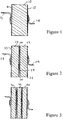
- a prior art ceramic PTC thermistor comprising a flat disc 10 of PTC semiconductor material, specifically a barium titanate ceramic which is doped to render it semiconducting.
- the opposite flat faces of the disc 10 are provided with metallic electrodes 11, 12, deposited for example by a sputtering process.
- Terminal wires 13, 14 are connected to the electrodes 11, 12 by soldering.
- Figure 2 shows a thermistor device in accordance with this invention, comprising two flat discs 20, 22 of the ceramic PTC semiconductor material, each disc being provided with metallic electrodes 23, 24 and 25, 26 over its opposite faces.
- the two discs 20, 22 are bonded together face-to-face by a layer of solder 27, which preferably terminates short of the peripheral edges of the discs.
- Terminal wires 28, 29 are soldered to the outer electrodes 23, 26 of the composite device.
- the overall thickness of PTC material between the outer electrodes 23, 26 determines the maximum voltage which the device is able to withstand. Because the two discs are in thermal contact, any tendency is avoided of one disc heating up significantly quicker than the other and therefore adopting its high resistance on its own. We have found, however, that the device of Figure 2 is able to withstand a significantly greater surge current than a device of Figure 1 having the same diameter and overall thickness. One possible reason for this is that the provision of electrodes (24, 25) within the device leads to a more uniform distribution of current through the ceramic bodies, and therefore more uniform heating resulting in less mechanical stress.
- the discs comprise a quantity of powder which has been pressed and then sintered, the density and resistivity of the ceramic material may be more uniform in a thin disc than in a thick disc, leading to a more uniform temperature distribution when subjected to a fault current.
- a degree of radial movement of one disc relative to the other may occur, in the device of Figure 2, particularly as the layer of solder 27 terminates short of the peripheral edges of the discs.
- one disc it is possible for one disc to heat and expand more rapidly than the other, without creating excessive mechanical stress within either disc.
- the device of Figure 2 comprises two discs disposed face-to-face in thermal contact and connected electrically in series, the device may comprise any number of discs mounted in a stack, such as three discs 30, 32, 34 as shown in Figure 3.
- Figures 2 and 3 show devices comprising discs, flat PTC ceramic bodies of any alternative cross-sectional shape may be employed.
- Figures 2 and 3 each show flat ceramic bodies provided with electrodes over their opposite faces and then bonded together, they may instead be mechanically clamped together e.g. under spring pressure.
Landscapes
- Engineering & Computer Science (AREA)
- Microelectronics & Electronic Packaging (AREA)
- Ceramic Engineering (AREA)
- Physics & Mathematics (AREA)
- Electromagnetism (AREA)
- Thermistors And Varistors (AREA)
Applications Claiming Priority (2)
| Application Number | Priority Date | Filing Date | Title |
|---|---|---|---|
| GB919120576A GB9120576D0 (en) | 1991-09-27 | 1991-09-27 | Thermistor |
| GB9120576 | 1991-09-27 |
Publications (1)
| Publication Number | Publication Date |
|---|---|
| EP0534775A1 true EP0534775A1 (fr) | 1993-03-31 |
Family
ID=10702069
Family Applications (1)
| Application Number | Title | Priority Date | Filing Date |
|---|---|---|---|
| EP92308746A Withdrawn EP0534775A1 (fr) | 1991-09-27 | 1992-09-25 | Thermistance |
Country Status (3)
| Country | Link |
|---|---|
| EP (1) | EP0534775A1 (fr) |
| JP (1) | JPH07201516A (fr) |
| GB (1) | GB9120576D0 (fr) |
Cited By (5)
| Publication number | Priority date | Publication date | Assignee | Title |
|---|---|---|---|---|
| EP0756291A3 (fr) * | 1995-07-18 | 1997-08-20 | Siemens Matsushita Components | Thermistor pour la protection contre les surtensions et méthode de fabrication |
| WO1997047018A1 (fr) * | 1996-06-03 | 1997-12-11 | Raychem Corporation | Procede pour former une electrode sur un substrat |
| US6922131B2 (en) * | 2000-01-11 | 2005-07-26 | Tyco Electronics Corporation | Electrical device |
| CN105225778A (zh) * | 2015-09-29 | 2016-01-06 | 上海神沃电子有限公司 | 一种电路保护元件及其制造工艺 |
| CN113692627A (zh) * | 2019-04-18 | 2021-11-23 | Tdk电子股份有限公司 | 电子器件 |
Citations (4)
| Publication number | Priority date | Publication date | Assignee | Title |
|---|---|---|---|---|
| US4259657A (en) * | 1978-05-17 | 1981-03-31 | Matsushita Electric Industrial Co., Ltd. | Self heat generation type positive characteristic thermistor and manufacturing method thereof |
| JPS5653429A (en) * | 1979-10-05 | 1981-05-13 | Seishi Tanaka | Controlling device for braking torque of water dynamometer |
| JPH01110701A (ja) * | 1987-10-23 | 1989-04-27 | Murata Mfg Co Ltd | 正の抵抗温度特性を有する半導体磁器 |
| DE3905443A1 (de) * | 1988-02-26 | 1989-09-28 | Murata Manufacturing Co | Ptc-thermistorvorrichtung mit einer ptc-thermistoreinheit in einem gehaeuse |
-
1991
- 1991-09-27 GB GB919120576A patent/GB9120576D0/en active Pending
-
1992
- 1992-09-25 EP EP92308746A patent/EP0534775A1/fr not_active Withdrawn
- 1992-09-28 JP JP28236092A patent/JPH07201516A/ja active Pending
Patent Citations (4)
| Publication number | Priority date | Publication date | Assignee | Title |
|---|---|---|---|---|
| US4259657A (en) * | 1978-05-17 | 1981-03-31 | Matsushita Electric Industrial Co., Ltd. | Self heat generation type positive characteristic thermistor and manufacturing method thereof |
| JPS5653429A (en) * | 1979-10-05 | 1981-05-13 | Seishi Tanaka | Controlling device for braking torque of water dynamometer |
| JPH01110701A (ja) * | 1987-10-23 | 1989-04-27 | Murata Mfg Co Ltd | 正の抵抗温度特性を有する半導体磁器 |
| DE3905443A1 (de) * | 1988-02-26 | 1989-09-28 | Murata Manufacturing Co | Ptc-thermistorvorrichtung mit einer ptc-thermistoreinheit in einem gehaeuse |
Non-Patent Citations (2)
| Title |
|---|
| PATENT ABSTRACTS OF JAPAN vol. 13, no. 352 (E-801)8 August 1989 & JP-A-01 110 701 ( MURATA MFG ) * |
| PATENT ABSTRACTS OF JAPAN vol. 5, no. 110 (P-71)17 July 1981 & JP-A-56 053 429 ( MATSUSHITA ELECTRIC ) 13 May 1981 * |
Cited By (8)
| Publication number | Priority date | Publication date | Assignee | Title |
|---|---|---|---|---|
| EP0756291A3 (fr) * | 1995-07-18 | 1997-08-20 | Siemens Matsushita Components | Thermistor pour la protection contre les surtensions et méthode de fabrication |
| WO1997047018A1 (fr) * | 1996-06-03 | 1997-12-11 | Raychem Corporation | Procede pour former une electrode sur un substrat |
| US5720859A (en) * | 1996-06-03 | 1998-02-24 | Raychem Corporation | Method of forming an electrode on a substrate |
| US6922131B2 (en) * | 2000-01-11 | 2005-07-26 | Tyco Electronics Corporation | Electrical device |
| CN105225778A (zh) * | 2015-09-29 | 2016-01-06 | 上海神沃电子有限公司 | 一种电路保护元件及其制造工艺 |
| CN113692627A (zh) * | 2019-04-18 | 2021-11-23 | Tdk电子股份有限公司 | 电子器件 |
| CN113692627B (zh) * | 2019-04-18 | 2023-10-31 | Tdk电子股份有限公司 | 电子器件 |
| US11875925B2 (en) | 2019-04-18 | 2024-01-16 | Tdk Electronics Ag | Thermistor, varistor or capacitor component with a fusible connecting element between the main body of the component |
Also Published As
| Publication number | Publication date |
|---|---|
| GB9120576D0 (en) | 1991-11-06 |
| JPH07201516A (ja) | 1995-08-04 |
Similar Documents
| Publication | Publication Date | Title |
|---|---|---|
| US7660096B2 (en) | Circuit protection device having thermally coupled MOV overvoltage element and PPTC overcurrent element | |
| US4780598A (en) | Composite circuit protection devices | |
| US4249224A (en) | Surge voltage arrester with fail-safe feature | |
| US5153805A (en) | Temperature-compensated thermal protector | |
| US4233641A (en) | Line protector for a communications circuit | |
| US3978443A (en) | Fusible resistor | |
| US6757963B2 (en) | Method of joining components using a silver-based composition | |
| US5379022A (en) | Thermistor device with extended operating range | |
| US5057811A (en) | Electrothermal sensor | |
| US20020125982A1 (en) | Surface mount electrical device with multiple ptc elements | |
| EP0534775A1 (fr) | Thermistance | |
| WO1997049102A1 (fr) | Appareil electrique pour la protection des circuits electriques contre les surintensites | |
| US5537286A (en) | Method of preparing planar PTC circuit protection devices | |
| JPH06511617A (ja) | 電気設備の過負荷および短絡防護装置 | |
| US5929744A (en) | Current limiting device with at least one flexible electrode | |
| EP1444704A1 (fr) | Pave resistif a courant de surtension | |
| EP0346263B1 (fr) | Protecteur thermique à résistance variable et méthode de fabrication | |
| US5977861A (en) | Current limiting device with grooved electrode structure | |
| US6252493B1 (en) | High current varistor | |
| CA2023286C (fr) | Dispositif de protection thermique a compensation de temperature | |
| JPS6242460Y2 (fr) | ||
| JPH083998Y2 (ja) | サージ吸収器 | |
| CA1333411C (fr) | Dispositif de protection de circuit, composite | |
| JPH08236304A (ja) | 保護素子 | |
| JPS59136901A (ja) | 非直線性素子 |
Legal Events
| Date | Code | Title | Description |
|---|---|---|---|
| PUAI | Public reference made under article 153(3) epc to a published international application that has entered the european phase |
Free format text: ORIGINAL CODE: 0009012 |
|
| AK | Designated contracting states |
Kind code of ref document: A1 Designated state(s): AT BE DE FR GB IT SE |
|
| 18D | Application deemed to be withdrawn |
Effective date: 19931002 |