EP0536708B1 - Elektrischer Antischwingungsverbinder - Google Patents
Elektrischer Antischwingungsverbinder Download PDFInfo
- Publication number
- EP0536708B1 EP0536708B1 EP92117081A EP92117081A EP0536708B1 EP 0536708 B1 EP0536708 B1 EP 0536708B1 EP 92117081 A EP92117081 A EP 92117081A EP 92117081 A EP92117081 A EP 92117081A EP 0536708 B1 EP0536708 B1 EP 0536708B1
- Authority
- EP
- European Patent Office
- Prior art keywords
- arm
- electrical connector
- connector
- vibration
- panel
- Prior art date
- Legal status (The legal status is an assumption and is not a legal conclusion. Google has not performed a legal analysis and makes no representation as to the accuracy of the status listed.)
- Expired - Lifetime
Links
Images
Classifications
-
- H—ELECTRICITY
- H01—ELECTRIC ELEMENTS
- H01R—ELECTRICALLY-CONDUCTIVE CONNECTIONS; STRUCTURAL ASSOCIATIONS OF A PLURALITY OF MUTUALLY-INSULATED ELECTRICAL CONNECTING ELEMENTS; COUPLING DEVICES; CURRENT COLLECTORS
- H01R13/00—Details of coupling devices of the kinds covered by groups H01R12/70 or H01R24/00 - H01R33/00
- H01R13/73—Means for mounting coupling parts to apparatus or structures, e.g. to a wall
- H01R13/74—Means for mounting coupling parts in openings of a panel
- H01R13/741—Means for mounting coupling parts in openings of a panel using snap fastening means
- H01R13/743—Means for mounting coupling parts in openings of a panel using snap fastening means integral with the housing
Definitions
- This invention generally relates to the art of electrical connectors and, particularly, to an anti-vibration electrical connector which has means for relieving stress in an anti-vibration arm thereof.
- Electrical connectors are used in a variety of applications or environments wherein it is desirable or necessary to protect the connector components or the mating connection of the connector with a complementary connector from vibrations due to the mounting of the connector.
- the applications can range from automobiles to refrigerators and countless other environments.
- anti-vibration means can take a wide range of forms, from fastening means for rigidly fixing the connector to its support, to more versatile means such as snap-action mounting means.
- a connector housing of the type disclosed in document US-A-3523269 can be molded with an integral anti-vibration arm which is yieldable or sufficiently flexible to bias the connector against its mount and to take up any slack therebetween which might otherwise result in rattling of the connector in response to vibrations.
- the anti-vibration arm could engage and yield against one side of a panel, for instance, in a panel-mounted connector, or the anti-vibration arm might yieldably engage an abutment surface on a complementary connector.
- anti-vibration arms, flanges, or the like which are integral with a molded dielectric connector housing
- the anti-vibration means are subject to stresses, particularly when cantilevered outwardly from a substantially rigidified housing wall.
- Dielectric housings of most connectors are fabricated of plastic material, and the cantilevered anti-vibration arms, flanges or the like too often are subject to breakage when encountering undue stress.
- This invention is directed to solving these problems by providing a new and improved electrical connector which includes stress relief means in its anti-vibration means.
- An object, therefore, of the invention is to provide an electrical connector with anti-vibration means in which is incorporated stress relief means.
- the electrical connector is adapted for mounting in an aperture in a panel or the like and includes an appropriate housing.
- a yieldable or flexible anti-vibration arm projects from the housing for engaging the panel when the connector is mounted in the aperture to prevent vibration between the connector and the panel.
- Recess means are provided in the anti-vibration arm at a location to relieve stress in the arm during yielding thereof.
- the anti-vibration arm is cantilevered from a rigid wall of the housing, as where the wall is thickened or rigidified by a polarizing rib.
- the recess means is formed in the antivibration arm either at or near the portion of the arm close to the polarized rib and may be in the form of a hole or rectangular portion either partially or completely through the arm.
- the recess means in the specific embodiment comprises at least one through hole in the anti-vibration arm immediately adjacent the polarized rib.
- the anti-vibration arm is generally L-shaped, with one leg of the L-shaped arm projecting toward the panel for engagement therewith and with the through hole being formed in the other leg of the L-shaped arm adjacent the housing.
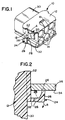
- an electrical connector generally designated 10
- a housing 12 having passages therethrough (not shown) for receiving and positioning appropriate terminals.
- the passages communicate with apertures 14 at the front end of the connector, the apertures being provided for receiving tubular portions of a complementary electrical connector (not shown) which has terminals for mating with the terminals of connector 10.
- a latch ramp 16 is formed integrally with the top of housing 12 for snapping engagement with a snap latch of the complementary connector.
- the entire connector housing 12 is integrally molded of dielectric material, such as plastic or the like.
- Electrical connector 10 is designed as a panel-mounted connector for mounting in an aperture in a panel or the like.
- the anti-vibration means including the stress relief means of the invention, can be used in a variety of applications where the connector is provided with an anti-vibration means, such as a cantilevered arm, a flange or the like.
- a resilient latch finger 18 projects outwardly from opposite sides of the connector (only one latch finger 18 being visible in Fig. 1).
- the latch finger has a ramp surface 20 for positioning through the aperture in the panel to bias the finger inwardly in the direction of arrow "A" until a shoulder 22 snaps behind the side of the panel opposite the insertion direction of the connector.
- Anti-vibration means in the form of a generally L-shaped anti-vibration arm, generally designated 24, projects outwardly from each opposite side of connector housing 12 spaced longitudinally from shoulder 22 of latch finger 18.
- the L-shaped arm includes one leg 26 projecting toward shoulder 22 and a panel sandwiched therebetween, and the other leg 28 of the L-shaped arm projects outwardly from a side wall 30 of housing 12 in a cantilevered fashion in contact with a polarized rib 32.
- cantilevered anti-vibration arm 24 is shown with the distal end of leg 26 engaging a back side 34 of a panel 36.
- Latch finger 18 and its shoulder 22 are not visible in Figure 2, because the figure is a section through anti-vibration arm 24, and the arm is offset relative to the latch finger as can be seen in Figure 1.
- the spacing therebetween is such that the arm yields in the direction of arrow "B" from its static position (shown by dotted lines) and its stressed position (shown in full lines).
- the stress without the stress relieving means 38 would be greatest at a point on leg 28 just above the polarized rib.
- the invention contemplates providing stress relief means in anti-vibration arm 24 to minimize stresses causes by yielding or flexing of the arm and to reduce or eliminate breakage of the arm. More particularly, recess means in the form of a through hole 38 is provided in leg 28 of the L-shaped arm. In other words, the hole is provided in the leg of the arm which is subject to flexing or bending relative to rigidified wall 30 of the connector housing.
- through hole 38 is located immediately adjacent polarizing rib 32.
- the hole is in direct alignment with polarizing rib 32 and may be of substantially the same cross-sectional dimensions as that of the rib. This arrangement and dimensioning is easily fabricated during integral molding of the entire electrical connector housing by a core-thru at the location of the stress relief hole.
Landscapes
- Connector Housings Or Holding Contact Members (AREA)
- Details Of Connecting Devices For Male And Female Coupling (AREA)
Claims (8)
- Elektrischer Steckverbinder (10) zum Anbringen in einer Öffnung einer Platte oder Konsole mit:
einem Gehäuse (12), das an einer Außenfläche durch eine Ausrichtungs- oder Verpolungsschutzeinrichtung (32) verdickt ist;
einem nachgiebigen Antivibrationsarm (24), der mit der Ausrichtungs- oder Verpolungsschutzeinrichtung (32) einstückig ausgebildet ist und so von dem Gehäuse vorsteht, daß er beim Anbringen in der Öffnung mit der Platte oder der Konsole in Eingriff tritt, um Vibrationen zwischen dem Steckverbinder und der Platte oder der Konsole zu verhindern,
dadurch gekennzeichnet, daß
in dem Antivibrationsarm an einer Stelle eine Aussparung (38) angeordnet ist, die im großen und ganzen die gleiche Querschnittsfläche wie die Ausrichtungs- oder Verpolungsschutzeinrichtung aufweist, um die Spannungen in dem Arm abzubauen, die durch das Biegen der Ausrichtungs- oder Verpolungsschutzeinrichtung hervorgerufen werden. - Elektrischer Steckverbinder (10) nach Anspruch 1, bei dem das Gehäuse (12) eine starre Wand umfaßt, von der aus der Antivibrationsarm (24) vorsteht, und bei dem die Aussparung (38) benachbart zu der Ausrichtungs- oder Verpolungsschutzeinrichtung (32) angeordnet ist.
- Elektrischer Steckverbinder (10) nach Anspruch 2, bei dem die Aussparung (38) in dem Antivibrationsarm (24) zumindest ein Durchgangsloch umfaßt.
- Elektrischer Steckverbinder (10) nach Anspruch 2, bei dem die Aussparung (38) zumindest ein teilweise durch den Antivibrationsarm (24) hindurchgehendes Loch umfaßt.
- Elektrischer Steckverbinder (10) nach Anspruch 4, bei dem das teilweise durch den Antivibrationsarm (24) hindurchgehende Loch (38) eine rechteckige Form aufweist.
- Elektrischer Steckverbinder (10) nach Anspruch 1, bei dem die Ausrichtungs- oder Verpolungsschutzeinrichtung eine längliche Rippe umfaßt.
- Elektrischer Steckverbinder (10) nach Anspruch 1, bei dem die Aussparung (38) in dem Antivibrationsarm (24) zumindest ein Durchgangsloch umfaßt.
- Elektrischer Steckverbinder (10) nach Anspruch 1, bei dem das Gehäuse (12) eine Wand (30) umfaßt und bei dem der Antivibrationsarm (24) im großen und ganzen L-förmig ist und von der Wand (30) freitragend nach außen vorsteht, wobei ein Schenkel (26) des L-förmigen Arms (24) in Richtung auf die Platte oder die Konsole vorsteht und wobei die Aussparung (38) in dem anderen Schenkel (28) des L-förmigen Arms ausgebildet ist.
Applications Claiming Priority (2)
| Application Number | Priority Date | Filing Date | Title |
|---|---|---|---|
| US07/774,405 US5131867A (en) | 1990-10-15 | 1991-10-10 | Anti-vibration electrical connector with stress relief |
| US774405 | 2001-01-31 |
Publications (3)
| Publication Number | Publication Date |
|---|---|
| EP0536708A2 EP0536708A2 (de) | 1993-04-14 |
| EP0536708A3 EP0536708A3 (en) | 1993-07-28 |
| EP0536708B1 true EP0536708B1 (de) | 1995-09-27 |
Family
ID=25101132
Family Applications (1)
| Application Number | Title | Priority Date | Filing Date |
|---|---|---|---|
| EP92117081A Expired - Lifetime EP0536708B1 (de) | 1991-10-10 | 1992-10-07 | Elektrischer Antischwingungsverbinder |
Country Status (3)
| Country | Link |
|---|---|
| EP (1) | EP0536708B1 (de) |
| JP (1) | JP2520076B2 (de) |
| DE (1) | DE69205111T2 (de) |
Families Citing this family (4)
| Publication number | Priority date | Publication date | Assignee | Title |
|---|---|---|---|---|
| JP2727869B2 (ja) * | 1992-05-29 | 1998-03-18 | 住友電装株式会社 | ボディ固定用コネクタ |
| GB9416986D0 (en) * | 1994-08-23 | 1994-10-12 | Amp Gmbh | Electrical connector with anti-chattering interconnection means |
| JPH10335007A (ja) * | 1997-06-02 | 1998-12-18 | Sumitomo Wiring Syst Ltd | コネクタ |
| US20220285864A1 (en) * | 2019-07-29 | 2022-09-08 | Signify Holding B.V. | Electrical connector assembly |
Family Cites Families (4)
| Publication number | Priority date | Publication date | Assignee | Title |
|---|---|---|---|---|
| US3523269A (en) * | 1968-03-08 | 1970-08-04 | Essex International Inc | Panel locking terminal connector block |
| JPS5239567A (en) * | 1975-09-23 | 1977-03-26 | Sato Fumio | Trimming die for making bolt in cold working |
| US4687276A (en) * | 1986-09-05 | 1987-08-18 | The Babcock & Wilcox Company | Connector clip for ribbon cable connector |
| JPH0235182U (de) * | 1988-08-31 | 1990-03-07 |
-
1992
- 1992-09-03 JP JP4260709A patent/JP2520076B2/ja not_active Expired - Lifetime
- 1992-10-07 EP EP92117081A patent/EP0536708B1/de not_active Expired - Lifetime
- 1992-10-07 DE DE69205111T patent/DE69205111T2/de not_active Expired - Fee Related
Also Published As
| Publication number | Publication date |
|---|---|
| JP2520076B2 (ja) | 1996-07-31 |
| DE69205111D1 (de) | 1995-11-02 |
| EP0536708A3 (en) | 1993-07-28 |
| JPH05217625A (ja) | 1993-08-27 |
| EP0536708A2 (de) | 1993-04-14 |
| DE69205111T2 (de) | 1996-05-09 |
Similar Documents
| Publication | Publication Date | Title |
|---|---|---|
| US5131867A (en) | Anti-vibration electrical connector with stress relief | |
| JP3020025B2 (ja) | パネル取付型電気コネクタ | |
| US5249982A (en) | Panel mounted electrical connector with improved sealing system | |
| US6312285B1 (en) | Panel mounting system for electrical connectors | |
| US10770876B2 (en) | Electrical connection box and ground connection structure thereof | |
| US4978313A (en) | Movable connector | |
| KR100395392B1 (ko) | 커넥터 조립체용 emi 가스켓 | |
| US20100271763A1 (en) | Clamp and electronic device accommodating unit | |
| US6272021B1 (en) | Circuit device | |
| US20050221656A1 (en) | Connector which can easily be mounted to an object and provided with EMI protection | |
| JP2538832B2 (ja) | 電気コネクタ用パネル取り付け保持器 | |
| EP0840402B1 (de) | Verbinder | |
| US6174185B1 (en) | Panel mounted connector | |
| US5547394A (en) | Panel mounted electrical connector | |
| EP0536708B1 (de) | Elektrischer Antischwingungsverbinder | |
| KR100396978B1 (ko) | 래칭 포스트, 래칭 장치 및 전기 커넥터 | |
| US6149444A (en) | Electrical connector with grounding means | |
| KR101234175B1 (ko) | 자체 정렬 연결구 | |
| KR0141085B1 (ko) | 콘넥터 하우징 및 이를 사용하는 콘넥터 | |
| EP4067794A1 (de) | Steuergehäusebauteil | |
| US6083042A (en) | Adjustable connecting device | |
| JPH11250988A (ja) | コネクタ | |
| US6166892A (en) | Connector with built-in resettable power regulation | |
| CN114498169B (zh) | 一种连接器、连接器组件及电子设备 | |
| KR0120594Y1 (ko) | 필터기능을 갖는 다중 단자 전기 커텍터 조립체 |
Legal Events
| Date | Code | Title | Description |
|---|---|---|---|
| PUAI | Public reference made under article 153(3) epc to a published international application that has entered the european phase |
Free format text: ORIGINAL CODE: 0009012 |
|
| AK | Designated contracting states |
Kind code of ref document: A2 Designated state(s): DE FR GB IT |
|
| PUAL | Search report despatched |
Free format text: ORIGINAL CODE: 0009013 |
|
| AK | Designated contracting states |
Kind code of ref document: A3 Designated state(s): DE FR GB IT |
|
| 17P | Request for examination filed |
Effective date: 19930929 |
|
| 17Q | First examination report despatched |
Effective date: 19950126 |
|
| GRAA | (expected) grant |
Free format text: ORIGINAL CODE: 0009210 |
|
| AK | Designated contracting states |
Kind code of ref document: B1 Designated state(s): DE FR GB IT |
|
| ITF | It: translation for a ep patent filed | ||
| ET | Fr: translation filed | ||
| REF | Corresponds to: |
Ref document number: 69205111 Country of ref document: DE Date of ref document: 19951102 |
|
| PLBE | No opposition filed within time limit |
Free format text: ORIGINAL CODE: 0009261 |
|
| 26N | No opposition filed | ||
| PGFP | Annual fee paid to national office [announced via postgrant information from national office to epo] |
Ref country code: GB Payment date: 19990913 Year of fee payment: 8 |
|
| PGFP | Annual fee paid to national office [announced via postgrant information from national office to epo] |
Ref country code: FR Payment date: 19991013 Year of fee payment: 8 |
|
| PGFP | Annual fee paid to national office [announced via postgrant information from national office to epo] |
Ref country code: DE Payment date: 19991027 Year of fee payment: 8 |
|
| PG25 | Lapsed in a contracting state [announced via postgrant information from national office to epo] |
Ref country code: GB Free format text: LAPSE BECAUSE OF NON-PAYMENT OF DUE FEES Effective date: 20001007 |
|
| GBPC | Gb: european patent ceased through non-payment of renewal fee |
Effective date: 20001007 |
|
| PG25 | Lapsed in a contracting state [announced via postgrant information from national office to epo] |
Ref country code: FR Free format text: LAPSE BECAUSE OF NON-PAYMENT OF DUE FEES Effective date: 20010629 |
|
| PG25 | Lapsed in a contracting state [announced via postgrant information from national office to epo] |
Ref country code: DE Free format text: LAPSE BECAUSE OF NON-PAYMENT OF DUE FEES Effective date: 20010703 |
|
| REG | Reference to a national code |
Ref country code: FR Ref legal event code: ST |
|
| PG25 | Lapsed in a contracting state [announced via postgrant information from national office to epo] |
Ref country code: IT Free format text: LAPSE BECAUSE OF NON-PAYMENT OF DUE FEES;WARNING: LAPSES OF ITALIAN PATENTS WITH EFFECTIVE DATE BEFORE 2007 MAY HAVE OCCURRED AT ANY TIME BEFORE 2007. THE CORRECT EFFECTIVE DATE MAY BE DIFFERENT FROM THE ONE RECORDED. Effective date: 20051007 |