EP0538600A2 - Procédé pour accélerer l'intervention de freinage dans le mode de régulation d'antipatinage au démarrage et un système de freinage hydraulique pour la - Google Patents
Procédé pour accélerer l'intervention de freinage dans le mode de régulation d'antipatinage au démarrage et un système de freinage hydraulique pour la Download PDFInfo
- Publication number
- EP0538600A2 EP0538600A2 EP92115116A EP92115116A EP0538600A2 EP 0538600 A2 EP0538600 A2 EP 0538600A2 EP 92115116 A EP92115116 A EP 92115116A EP 92115116 A EP92115116 A EP 92115116A EP 0538600 A2 EP0538600 A2 EP 0538600A2
- Authority
- EP
- European Patent Office
- Prior art keywords
- brake
- pump
- valve
- line
- drive motor
- Prior art date
- Legal status (The legal status is an assumption and is not a legal conclusion. Google has not performed a legal analysis and makes no representation as to the accuracy of the status listed.)
- Granted
Links
Images

Classifications
-
- B—PERFORMING OPERATIONS; TRANSPORTING
- B60—VEHICLES IN GENERAL
- B60T—VEHICLE BRAKE CONTROL SYSTEMS OR PARTS THEREOF; BRAKE CONTROL SYSTEMS OR PARTS THEREOF, IN GENERAL; ARRANGEMENT OF BRAKING ELEMENTS ON VEHICLES IN GENERAL; PORTABLE DEVICES FOR PREVENTING UNWANTED MOVEMENT OF VEHICLES; VEHICLE MODIFICATIONS TO FACILITATE COOLING OF BRAKES
- B60T8/00—Arrangements for adjusting wheel-braking force to meet varying vehicular or ground-surface conditions, e.g. limiting or varying distribution of braking force
- B60T8/32—Arrangements for adjusting wheel-braking force to meet varying vehicular or ground-surface conditions, e.g. limiting or varying distribution of braking force responsive to a speed condition, e.g. acceleration or deceleration
- B60T8/34—Arrangements for adjusting wheel-braking force to meet varying vehicular or ground-surface conditions, e.g. limiting or varying distribution of braking force responsive to a speed condition, e.g. acceleration or deceleration having a fluid pressure regulator responsive to a speed condition
- B60T8/40—Arrangements for adjusting wheel-braking force to meet varying vehicular or ground-surface conditions, e.g. limiting or varying distribution of braking force responsive to a speed condition, e.g. acceleration or deceleration having a fluid pressure regulator responsive to a speed condition comprising an additional fluid circuit including fluid pressurising means for modifying the pressure of the braking fluid, e.g. including wheel driven pumps for detecting a speed condition, or pumps which are controlled by means independent of the braking system
- B60T8/404—Control of the pump unit
- B60T8/4045—Control of the pump unit involving ON/OFF switching
-
- B—PERFORMING OPERATIONS; TRANSPORTING
- B60—VEHICLES IN GENERAL
- B60T—VEHICLE BRAKE CONTROL SYSTEMS OR PARTS THEREOF; BRAKE CONTROL SYSTEMS OR PARTS THEREOF, IN GENERAL; ARRANGEMENT OF BRAKING ELEMENTS ON VEHICLES IN GENERAL; PORTABLE DEVICES FOR PREVENTING UNWANTED MOVEMENT OF VEHICLES; VEHICLE MODIFICATIONS TO FACILITATE COOLING OF BRAKES
- B60T8/00—Arrangements for adjusting wheel-braking force to meet varying vehicular or ground-surface conditions, e.g. limiting or varying distribution of braking force
- B60T8/32—Arrangements for adjusting wheel-braking force to meet varying vehicular or ground-surface conditions, e.g. limiting or varying distribution of braking force responsive to a speed condition, e.g. acceleration or deceleration
- B60T8/34—Arrangements for adjusting wheel-braking force to meet varying vehicular or ground-surface conditions, e.g. limiting or varying distribution of braking force responsive to a speed condition, e.g. acceleration or deceleration having a fluid pressure regulator responsive to a speed condition
- B60T8/48—Arrangements for adjusting wheel-braking force to meet varying vehicular or ground-surface conditions, e.g. limiting or varying distribution of braking force responsive to a speed condition, e.g. acceleration or deceleration having a fluid pressure regulator responsive to a speed condition connecting the brake actuator to an alternative or additional source of fluid pressure, e.g. traction control systems
- B60T8/4809—Traction control, stability control, using both the wheel brakes and other automatic braking systems
- B60T8/4827—Traction control, stability control, using both the wheel brakes and other automatic braking systems in hydraulic brake systems
- B60T8/4863—Traction control, stability control, using both the wheel brakes and other automatic braking systems in hydraulic brake systems closed systems
- B60T8/4872—Traction control, stability control, using both the wheel brakes and other automatic braking systems in hydraulic brake systems closed systems pump-back systems
Definitions
- the invention is based on a method for accelerating brake intervention in traction control operation of a hydraulic brake system for motor vehicles according to the preamble of claim 1 and a hydraulic brake system for motor vehicles with a traction control system according to the preamble of claim 4.
- Such hydraulic braking systems with traction control devices have already been proposed (DE patent application P 41 07 978.7; DE utility model application G 91 02 352.1), wherein the traction control devices normally have at least one self-priming pump for drawing in pressure medium through a suction line and one arranged in the suction line have closed charging valve and / or by means of a vacuum protection valve assigned to at least one wheel brake and a shut-off valve for providing pressures for carrying out traction control operation. Because the pressure medium has a high viscosity at low temperatures, At low temperatures, the pumps can only achieve disadvantageously slow brake interventions in traction control mode in the initial phase.
- the method according to the invention with the characterizing method steps of claim 1 and the hydraulic brake system operating according to this method with the characterizing features of claim 4 have the advantage that gas bubbles and / or bubbles which may have arisen as a result of cooling in the locked-in pressure medium are rinsed away, so that if the traction control operation begins later, quick brake interventions are required.
- the purging of the gas bubbles and / or the bubbles can be repeated at intervals, provided that no brake application and no traction control operation take place.
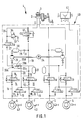
- FIG. 1 shows a first embodiment of the invention with a TT brake circuit division, in which the drive wheels of a drive axle belong to the brake circuit
- FIG. 2 shows a second embodiment of the same with K brake circuit division, in which the two drive wheels belonging to a drive axle and whose wheel brakes are distributed over two brake circuits.
- the brake system 1 has a pedal-operated, two-circuit master brake cylinder 2 with a pressure medium reservoir 3.
- a first brake circuit I of the brake system 1 is with wheel brakes 4, 5 non-driven vehicle wheels, for. B. the front axle of the vehicle connected.
- On a second brake circuit II the wheel brakes 6, 7 driven vehicle wheels, for. B. the rear axle of the vehicle connected.
- the brake circuit II associated with the solution according to the invention is explained in more detail below:
- the brake circuit II has a brake line 10 starting from the master brake cylinder 2, which is branched into two brake lines 11 and 12 leading to the wheel brakes 6 and 7, respectively.
- a shut-off valve 13 with a spring-operated passage position and an electromagnetically switchable blocking position is arranged on the master cylinder side.
- Pressure control valve arrangements 14, 15 for brake pressure modulation are provided on the wheel brake side.
- Each valve arrangement 14, 15 has an inlet valve 16, which is arranged in the corresponding brake line 11, 12 and controls the inflow of pressure medium to the wheel brake 6, 7, with a spring-operated passage position and an electromagnetically switchable blocking position.
- a return line 17, 18 extends from the respective brake line 11, 12.
- An outlet valve 19 of the pressure control valve arrangements 14, 15 is arranged in each of the return lines 17, 18.
- the outlet valve 19 has a spring-operated blocking position and an electromagnetically switchable passage position.
- the return lines 17 and 18 are combined in a return line 20 to which a storage chamber 21 is connected.
- a vacuum protection valve 20a is installed in the return line 20.
- This is designed in the manner of a check valve and has a valve seat 20b, a closing body 20c and a spring 20d.
- the vacuum protection valve 20a can be opened in the direction of the connected self-priming pump 25.
- the spring 20d is preloaded in such a way that the vacuum which can be generated by the pump is kept away from the wheel brakes 6, 7 when the outlet valves 19 are open.
- An electric drive motor 24 drives the high-pressure pump 25.
- the self-priming pump 25 is connected to the brake line 10 by means of a suction line 26, specifically between the master brake cylinder 2 and the shut-off valve 13.
- a suction line 26 specifically between the master brake cylinder 2 and the shut-off valve 13.
- a charging valve 27 with a spring-operated one Locked position and an electromagnetically switchable open position.
- the pump 25 is connected to the brake line 10 between the shut-off valve 13 and the pressure control valve arrangements 14, 15 by a delivery line 29.
- a damper chamber 30 and a throttle 31 are arranged in the delivery line 29.
- an outflow line 33 extends from the brake line 10 and leads to the intake line 26.
- the outflow line 33 is connected to the suction line 26.
- a pressure relief valve 34 with a response pressure of, for example, 100 bar.
- the brake system 1 is thus equipped with an anti-lock and traction control device 40.
- the latter has a control unit 41, with which signals from the speed sensors 42 that detect the rotational behavior of the vehicle wheels can be evaluated and converted into switching signals for the drive motor 24 of the pump 25 and the various electromagnetically actuated valves of the brake system 1.
- the device 40 is activated when there is a risk of blocking at least one vehicle wheel when braking or at least one of the drive wheels is subject to excessive slip when starting and accelerating.
- the control unit 41 switches the shut-off valve 13 into the locked position, the charging valve 27 into the open position and the drive motor 24 of the pump 25.
- the pump 25 sucks pressure medium from the reservoir 3 through the suction line 26 and feeds this pressure medium through the delivery line 29 into the brake line 10.
- the brake pressure in the wheel brake of the slipping drive wheel is modulated by correspondingly controlling the inlet valves 16 and the outlet valves 19 of the pressure control valve arrangements 14, 15.
- the control unit 41 is additionally set up in an essential manner according to the invention so that, when a vehicle equipped with it is put into operation, it repeats the drive motor of the pump 25 briefly at least once, preferably at intervals, and controls the charging valve 27 into the open position. This may be suppressed or terminated when brake application is started or traction control operation begins automatically.
- the pressure medium is transported by the pump 25 and, accordingly, the gas bubbles and / or bubbles which may have formed at the inlet of the pump 25 are flushed away.
- a disturbing noise development can take place from the opening of the charging valve 27.
- the shutoff valve 13 advantageously remains open, as a result of which less pumping noise occurs than when pumping against the opening pressure of the pressure limiting valve 34.
- FIG. 2 shows an embodiment of a brake system 1 a with K-brake circuit division, also called diagonal brake circuit division, in which, for example, a drivable front wheel is assigned to a brake circuit I or II. Accordingly, each of the two brake circuits I and II has a self-priming pump 25.
- the pressure control valve arrangements 14, 15 for wheel brakes 6, 7 of drivable wheels are correspondingly distributed among the brake circuits I and II.
- Charging valves 27, vacuum protection valves 20a and shut-off valves 13a as well as pressure limiting valves 34a are arranged in each brake circuit.
- the pressure relief valves 34a are integrated in the shut-off valves 13a.
- the German patent application P 41 02 626.8 proposes an embodiment for such an integration.
- the control unit 41a is developed in such a way that it can control the valves 13a and 27 additionally arranged in the brake circuit I. Because the valves of the brake system 1a of the exemplary embodiment according to FIG. 2 can basically be controlled in the same way as the valves of the exemplary embodiment according to FIG. 1, a further description of the control device 41a is unnecessary.
Landscapes
- Physics & Mathematics (AREA)
- Fluid Mechanics (AREA)
- Engineering & Computer Science (AREA)
- Transportation (AREA)
- Mechanical Engineering (AREA)
- Regulating Braking Force (AREA)
Applications Claiming Priority (2)
| Application Number | Priority Date | Filing Date | Title |
|---|---|---|---|
| DE4135062 | 1991-10-24 | ||
| DE4135062A DE4135062A1 (de) | 1991-10-24 | 1991-10-24 | Verfahren zum beschleunigen des bremseneingriffs im antriebsschlupfregelbetrieb und hydraulische bremsanlage zur durchfuehrung des verfahrens |
Publications (3)
| Publication Number | Publication Date |
|---|---|
| EP0538600A2 true EP0538600A2 (fr) | 1993-04-28 |
| EP0538600A3 EP0538600A3 (en) | 1993-05-26 |
| EP0538600B1 EP0538600B1 (fr) | 1994-11-30 |
Family
ID=6443291
Family Applications (1)
| Application Number | Title | Priority Date | Filing Date |
|---|---|---|---|
| EP92115116A Expired - Lifetime EP0538600B1 (fr) | 1991-10-24 | 1992-09-04 | Procédé pour accélerer l'intervention de freinage dans le mode de régulation d'antipatinage au démarrage et un système de freinage hydraulique pour la |
Country Status (4)
| Country | Link |
|---|---|
| US (1) | US5275476A (fr) |
| EP (1) | EP0538600B1 (fr) |
| JP (1) | JP3476487B2 (fr) |
| DE (2) | DE4135062A1 (fr) |
Cited By (5)
| Publication number | Priority date | Publication date | Assignee | Title |
|---|---|---|---|---|
| WO1996029219A1 (fr) * | 1995-03-22 | 1996-09-26 | Itt Automotive Europe Gmbh | Soupape electromagnetique a fonction de limitation de la pression, notamment pour systemes hydrauliques de freinage de vehicules a moteur a antiderapeur automatique et/ou a actionnement automatique des freins permettant de regler la dynamique de conduite |
| WO1996031375A1 (fr) * | 1995-04-07 | 1996-10-10 | Itt Automotive Europe Gmbh | Procede de connexion, dependant de la temperature, d'une source additionnelle de fluide hydraulique dans des systemes de freinage d'automobiles a regulation antipatinage, et systeme de freinage approprie pour mettre ledit procede en ×uvre |
| EP0696533A3 (fr) * | 1994-08-11 | 1996-11-06 | Nippon Denso Co | Dispositif pour le contrÔle de la pression du fluide de freinage pour véhicules |
| WO2007036433A1 (fr) * | 2005-09-27 | 2007-04-05 | Robert Bosch Gmbh | Regulation de vehicule a soupape de commande haute pression ouverte en permanence |
| WO2017012864A1 (fr) * | 2015-07-17 | 2017-01-26 | Robert Bosch Gmbh | Système de freinage hydraulique, procédé de fonctionnement du système de freinage hydraulique et appareil de commande pour la commande de composants du système de freinage hydraulique |
Families Citing this family (20)
| Publication number | Priority date | Publication date | Assignee | Title |
|---|---|---|---|---|
| JPH0840236A (ja) * | 1994-05-26 | 1996-02-13 | Aisin Seiki Co Ltd | 車両用液圧ブレーキ装置 |
| JPH08207734A (ja) * | 1994-05-26 | 1996-08-13 | Aisin Seiki Co Ltd | 車両用液圧ブレーキ装置 |
| DE59509187D1 (de) * | 1995-11-25 | 2001-05-17 | Micronas Gmbh | Signalmodifikationsschaltung |
| DE19638196B4 (de) * | 1995-12-30 | 2008-08-21 | Robert Bosch Gmbh | Vorrichtung zur Überwachung einer Bremsanlage |
| JPH09193781A (ja) * | 1995-12-30 | 1997-07-29 | Robert Bosch Gmbh | ブレーキ装置のモニタ装置 |
| DE19622726A1 (de) * | 1996-06-07 | 1997-12-11 | Bosch Gmbh Robert | Hydraulische Fahrzeugbremsanlage mit einer Blockierschutz- und Antriebsschlupfregeleinrichtung |
| DE19638920A1 (de) * | 1996-09-23 | 1998-03-26 | Teves Gmbh Alfred | Hydraulische Bremsanlage mit Bremskraftverstärkung |
| JPH10287224A (ja) * | 1997-04-17 | 1998-10-27 | Aisin Seiki Co Ltd | ブレーキ圧制御装置 |
| US6006520A (en) * | 1997-10-06 | 1999-12-28 | General Motors Corporation | Pneumatic assisted brake apply system |
| JP3726462B2 (ja) * | 1997-11-21 | 2005-12-14 | アイシン精機株式会社 | 車両の制動制御装置 |
| US5971503A (en) * | 1998-02-03 | 1999-10-26 | Ford Global Technologies, Inc. | Hydraulic control unit with ambient temperature compensation during fluid pressure delivery |
| JP3900671B2 (ja) * | 1998-04-22 | 2007-04-04 | アイシン精機株式会社 | 車両用液圧ブレーキ装置 |
| JP2000016267A (ja) * | 1998-07-01 | 2000-01-18 | Nissin Kogyo Kk | 車両のブレーキ液圧制御装置 |
| DE19902033A1 (de) * | 1998-09-16 | 2000-03-23 | Continental Teves Ag & Co Ohg | Drucksteuergerät |
| DE19859281A1 (de) | 1998-12-22 | 2000-06-29 | Bosch Gmbh Robert | Verfahren zur Kompensation der Temperaturabhängigkeit eines Spulenwiderstandes einer Ventilspule |
| JP4561464B2 (ja) * | 2005-05-11 | 2010-10-13 | 株式会社アドヴィックス | 車両用ブレーキ液圧制御装置 |
| KR100839708B1 (ko) * | 2006-12-07 | 2008-06-19 | 현대모비스 주식회사 | 차량의 전·후륜 제동 액압의 선형 감압 제어 및 기울기 차해소용 제동 유압 회로 |
| JP4909222B2 (ja) * | 2007-09-25 | 2012-04-04 | 株式会社アドヴィックス | 自動二輪車両の制動制御装置、及び自動二輪車両の制動制御方法 |
| JP4602428B2 (ja) * | 2008-02-14 | 2010-12-22 | 日信工業株式会社 | バーハンドル車両用ブレーキ液圧制御装置 |
| US8651587B2 (en) * | 2011-03-10 | 2014-02-18 | Continental Automotive Systems, Inc. | Electronically controlled hydraulic brake system |
Family Cites Families (20)
| Publication number | Priority date | Publication date | Assignee | Title |
|---|---|---|---|---|
| US2505213A (en) * | 1944-06-12 | 1950-04-25 | Wagner Electric Corp | Automatic circulating bleeding system for hydraulic brakes |
| US2962863A (en) * | 1956-02-01 | 1960-12-06 | Caroli Gerhard | Device for degassing pressure fluids of hydraulic power plants |
| DE3215739A1 (de) * | 1982-04-28 | 1983-11-03 | Robert Bosch Gmbh, 7000 Stuttgart | Antriebsschlupfregelung |
| DE3621000C2 (de) * | 1986-06-23 | 1994-04-14 | Teves Gmbh Alfred | Antriebsschlupfgeregelte Mehrkreisbremsanlage für Kraftfahrzeuge |
| DE3629564A1 (de) * | 1986-08-30 | 1988-03-03 | Teves Gmbh Alfred | Bremsanlage mit schlupfregelung |
| JP2677377B2 (ja) * | 1987-08-30 | 1997-11-17 | 株式会社デンソー | ブレーキ装置用アキュムレータの圧力制御装置 |
| DE3732161C2 (de) * | 1987-09-24 | 1996-09-05 | Teves Gmbh Alfred | Bremsanlage mit Blockierschutz- und/oder Antriebsschlupfregelung |
| DE3839178A1 (de) * | 1988-01-26 | 1989-08-03 | Daimler Benz Ag | Antiblockiersystem |
| JPH0245249A (ja) * | 1988-08-04 | 1990-02-15 | Akebono Brake Res & Dev Center Ltd | 車両のブレーキ液圧制御装置 |
| DE3832023C3 (de) * | 1988-09-21 | 1999-09-23 | Bosch Gmbh Robert | Vorrichtung zur Anfahrschlupfregelung (ASR) |
| DE3900851C1 (fr) * | 1989-01-13 | 1990-01-25 | Daimler-Benz Aktiengesellschaft, 7000 Stuttgart, De | |
| DE4000837B4 (de) * | 1990-01-13 | 2005-03-03 | Continental Teves Ag & Co. Ohg | Hydraulische Bremsanlage mit einer Einrichtung zur Brems- und/oder Antriebsschlupfregelung |
| DE4009640C1 (fr) * | 1990-03-26 | 1991-06-06 | Mercedes-Benz Aktiengesellschaft, 7000 Stuttgart, De | |
| DE4017872A1 (de) * | 1990-06-02 | 1991-12-05 | Bosch Gmbh Robert | Hydraulische fahrzeugbremsanlage mit antiblockiersystem und antriebsschlupfregelung |
| DE4034113A1 (de) * | 1990-10-26 | 1992-04-30 | Bosch Gmbh Robert | Hydraulische mehrkreis-bremsanlage, insbesondere fuer kraftfahrzeuge |
| DE4034112A1 (de) * | 1990-10-26 | 1992-04-30 | Bosch Gmbh Robert | Blockiergeschuetzte hydraulische mehrkreis-bremsanlage, insbesondere fuer kraftfahrzeuge |
| DE4035527C2 (de) * | 1990-11-08 | 2000-05-31 | Bosch Gmbh Robert | Hydraulische Bremsanlage |
| DE9102352U1 (de) * | 1991-02-28 | 1992-06-25 | Robert Bosch Gmbh, 7000 Stuttgart | Hydraulische Bremsanlage mit Antriebsschlupfregeleinrichtung |
| DE4107978C2 (de) * | 1991-03-13 | 1999-08-26 | Bosch Gmbh Robert | Verfahren zum Beschleunigen des Bremseneingriffs im Antriebsschlupfregelbetrieb und hydraulische Bremsanlage zur Durchführung des Verfahrens |
| DE4112759A1 (de) * | 1991-04-19 | 1992-10-22 | Bosch Gmbh Robert | Bremsdruckregelanlage |
-
1991
- 1991-10-24 DE DE4135062A patent/DE4135062A1/de not_active Withdrawn
-
1992
- 1992-09-04 DE DE59200849T patent/DE59200849D1/de not_active Expired - Fee Related
- 1992-09-04 EP EP92115116A patent/EP0538600B1/fr not_active Expired - Lifetime
- 1992-10-20 JP JP28122992A patent/JP3476487B2/ja not_active Expired - Fee Related
- 1992-10-23 US US07/965,316 patent/US5275476A/en not_active Expired - Lifetime
Cited By (5)
| Publication number | Priority date | Publication date | Assignee | Title |
|---|---|---|---|---|
| EP0696533A3 (fr) * | 1994-08-11 | 1996-11-06 | Nippon Denso Co | Dispositif pour le contrÔle de la pression du fluide de freinage pour véhicules |
| WO1996029219A1 (fr) * | 1995-03-22 | 1996-09-26 | Itt Automotive Europe Gmbh | Soupape electromagnetique a fonction de limitation de la pression, notamment pour systemes hydrauliques de freinage de vehicules a moteur a antiderapeur automatique et/ou a actionnement automatique des freins permettant de regler la dynamique de conduite |
| WO1996031375A1 (fr) * | 1995-04-07 | 1996-10-10 | Itt Automotive Europe Gmbh | Procede de connexion, dependant de la temperature, d'une source additionnelle de fluide hydraulique dans des systemes de freinage d'automobiles a regulation antipatinage, et systeme de freinage approprie pour mettre ledit procede en ×uvre |
| WO2007036433A1 (fr) * | 2005-09-27 | 2007-04-05 | Robert Bosch Gmbh | Regulation de vehicule a soupape de commande haute pression ouverte en permanence |
| WO2017012864A1 (fr) * | 2015-07-17 | 2017-01-26 | Robert Bosch Gmbh | Système de freinage hydraulique, procédé de fonctionnement du système de freinage hydraulique et appareil de commande pour la commande de composants du système de freinage hydraulique |
Also Published As
| Publication number | Publication date |
|---|---|
| EP0538600A3 (en) | 1993-05-26 |
| DE59200849D1 (de) | 1995-01-12 |
| JPH05213177A (ja) | 1993-08-24 |
| DE4135062A1 (de) | 1993-04-29 |
| US5275476A (en) | 1994-01-04 |
| EP0538600B1 (fr) | 1994-11-30 |
| JP3476487B2 (ja) | 2003-12-10 |
Similar Documents
| Publication | Publication Date | Title |
|---|---|---|
| EP0538600B1 (fr) | Procédé pour accélerer l'intervention de freinage dans le mode de régulation d'antipatinage au démarrage et un système de freinage hydraulique pour la | |
| DE3731603C2 (de) | Blockiergeschützte Fahrzeugbremsanlage | |
| DE4035527C2 (de) | Hydraulische Bremsanlage | |
| DE3832023C3 (de) | Vorrichtung zur Anfahrschlupfregelung (ASR) | |
| DE102011077329A1 (de) | Verfahren zur Regelung eines elektrohydraulischen Bremssystems sowie elektrohydraulisches Bremssystem | |
| DE4106336A1 (de) | Hydraulische bremsanlage, insbesondere fuer kraftfahrzeuge | |
| EP0460408A1 (fr) | Installation hydraulique de freinage pour véhicule avec système anti-blocage et contrôle de traction | |
| DE4213740A1 (de) | Verfahren zum Beschleunigen des Bremseneingriffs im Antriebsschlupfregelbetrieb und hydraulische Bremsanlage zur Durchführung des Verfahrens | |
| DE4107978C2 (de) | Verfahren zum Beschleunigen des Bremseneingriffs im Antriebsschlupfregelbetrieb und hydraulische Bremsanlage zur Durchführung des Verfahrens | |
| EP0605463A1 (fr) | Systeme hydraulique de freinage a blocage du differentiel, notamment pour vehicules a moteur. | |
| DE19537437B4 (de) | Verfahren und Vorrichtung zur Steuerung einer Bremsanlage eines Fahrzeugs | |
| DE3408872C2 (fr) | ||
| DE19537439B4 (de) | Verfahren und Vorrichtung zur Steuerung der Bremsanlage eines Fahrzeugs | |
| EP0837803B1 (fr) | Systeme de freinage hydraulique pour vehicule | |
| EP0459117A1 (fr) | Système de freinage hydraulique à double circuit | |
| DE102019210608A1 (de) | Verfahren zum Betrieb einer hydraulischen Fremdkraft-Fahrzeugbremsanlage für autonomes Fahren | |
| DE19525800C2 (de) | Antriebsschlupfregelsystem | |
| WO1993025417A1 (fr) | Systeme antiblocage | |
| DE102010042534A1 (de) | Schlupfgeregelte, hydraulische Fahrzeugbremsanlage | |
| DE10290794B4 (de) | Verfahren und Vorrichtung zur Steuerung einer blockiergeschützten Bremsanlage | |
| WO2001014193A1 (fr) | Procede pour faire fonctionner un systeme de freinage de vehicule presentant une regulation antipatinage | |
| EP1177121B1 (fr) | Procede de modulation de pressions de freinage | |
| EP0447796B1 (fr) | Système à freinage hydraulique à double circuit | |
| DE4024627A1 (de) | Hydraulische fahrzeugbremsanlage mit blockierschutz- und antriebsschlupfbegrenzungseinrichtung | |
| DE102012223319A1 (de) | Schlupfgeregelte hydraulische Fahrzeugbremsanlage |
Legal Events
| Date | Code | Title | Description |
|---|---|---|---|
| PUAI | Public reference made under article 153(3) epc to a published international application that has entered the european phase |
Free format text: ORIGINAL CODE: 0009012 |
|
| PUAL | Search report despatched |
Free format text: ORIGINAL CODE: 0009013 |
|
| AK | Designated contracting states |
Kind code of ref document: A2 Designated state(s): DE FR GB |
|
| AK | Designated contracting states |
Kind code of ref document: A3 Designated state(s): DE FR GB |
|
| 17P | Request for examination filed |
Effective date: 19931104 |
|
| 17Q | First examination report despatched |
Effective date: 19931125 |
|
| GRAA | (expected) grant |
Free format text: ORIGINAL CODE: 0009210 |
|
| AK | Designated contracting states |
Kind code of ref document: B1 Designated state(s): DE FR GB |
|
| REF | Corresponds to: |
Ref document number: 59200849 Country of ref document: DE Date of ref document: 19950112 |
|
| ET | Fr: translation filed | ||
| GBT | Gb: translation of ep patent filed (gb section 77(6)(a)/1977) |
Effective date: 19950419 |
|
| PLBE | No opposition filed within time limit |
Free format text: ORIGINAL CODE: 0009261 |
|
| 26N | No opposition filed | ||
| REG | Reference to a national code |
Ref country code: GB Ref legal event code: IF02 |
|
| PGFP | Annual fee paid to national office [announced via postgrant information from national office to epo] |
Ref country code: GB Payment date: 20020814 Year of fee payment: 11 |
|
| PGFP | Annual fee paid to national office [announced via postgrant information from national office to epo] |
Ref country code: FR Payment date: 20020918 Year of fee payment: 11 |
|
| PG25 | Lapsed in a contracting state [announced via postgrant information from national office to epo] |
Ref country code: GB Free format text: LAPSE BECAUSE OF NON-PAYMENT OF DUE FEES Effective date: 20030904 |
|
| GBPC | Gb: european patent ceased through non-payment of renewal fee | ||
| PG25 | Lapsed in a contracting state [announced via postgrant information from national office to epo] |
Ref country code: FR Free format text: LAPSE BECAUSE OF NON-PAYMENT OF DUE FEES Effective date: 20040528 |
|
| REG | Reference to a national code |
Ref country code: FR Ref legal event code: ST |
|
| PGFP | Annual fee paid to national office [announced via postgrant information from national office to epo] |
Ref country code: DE Payment date: 20071126 Year of fee payment: 16 |
|
| PG25 | Lapsed in a contracting state [announced via postgrant information from national office to epo] |
Ref country code: DE Free format text: LAPSE BECAUSE OF NON-PAYMENT OF DUE FEES Effective date: 20090401 |