EP0539897A2 - Système de production d'images à large champ - Google Patents
Système de production d'images à large champ Download PDFInfo
- Publication number
- EP0539897A2 EP0539897A2 EP92118256A EP92118256A EP0539897A2 EP 0539897 A2 EP0539897 A2 EP 0539897A2 EP 92118256 A EP92118256 A EP 92118256A EP 92118256 A EP92118256 A EP 92118256A EP 0539897 A2 EP0539897 A2 EP 0539897A2
- Authority
- EP
- European Patent Office
- Prior art keywords
- image data
- frame
- memory
- regard
- field
- Prior art date
- Legal status (The legal status is an assumption and is not a legal conclusion. Google has not performed a legal analysis and makes no representation as to the accuracy of the status listed.)
- Granted
Links
Images


Classifications
-
- H—ELECTRICITY
- H04—ELECTRIC COMMUNICATION TECHNIQUE
- H04N—PICTORIAL COMMUNICATION, e.g. TELEVISION
- H04N7/00—Television systems
- H04N7/18—Closed-circuit television [CCTV] systems, i.e. systems in which the video signal is not broadcast
-
- H—ELECTRICITY
- H04—ELECTRIC COMMUNICATION TECHNIQUE
- H04N—PICTORIAL COMMUNICATION, e.g. TELEVISION
- H04N5/00—Details of television systems
- H04N5/222—Studio circuitry; Studio devices; Studio equipment
- H04N5/262—Studio circuits, e.g. for mixing, switching-over, change of character of image, other special effects ; Cameras specially adapted for the electronic generation of special effects
-
- H—ELECTRICITY
- H04—ELECTRIC COMMUNICATION TECHNIQUE
- H04N—PICTORIAL COMMUNICATION, e.g. TELEVISION
- H04N5/00—Details of television systems
- H04N5/30—Transforming light or analogous information into electric information
- H04N5/33—Transforming infrared radiation
Definitions
- This invention relates to systems for creating images of a scene. More specifically, this invention relates to systems operative to generate a scene image spanning a wide field-of-regard.
- Infrared imaging systems are used in a variety of military and commercial applications to provide either an operator or a guidance system with a view of a scene. Such imaging systems are typically characterized as having a "field-of-regard", which refers to the angular breadth of the resultant scene image.
- a field-of-regard refers to the angular breadth of the resultant scene image.
- One benefit accruing from a wide field-of-regard is that a viewer of the wide-field image may observe individual objects therein within the context of a larger scene.
- increases in the field-of-regard generally come at the expense of decreases in image resolution within conventional imaging systems.
- the imaging system is designed to incorporate a pair of optical lenses.
- One of the lenses encompasses a wide field of view, while the other covers a relatively narrow field of view.
- the lenses are then mechanically moved in and out of the optical train of the imaging system to alternately provide a wide field-of-regard or improved resolution.
- One disadvantage of this approach is that the rate at which an operator may switch between the fields of view of the two lenses is limited by the response of the servo system used to alternately interpose the lenses within the optical train.
- an imaging sensor (typically having a relatively narrow field of view) is mounted on a gimbal scan mechanism.
- the gimbal is rotated to direct the field of view of the sensor to various regions within the field-of-regard, with frames of image data being produced by the sensor at a known rate (e.g. 60 Hz).
- a known rate e.g. 60 Hz.
- individual regions throughout the entire field-of-regard may be viewed in isolation using this method, a composite image of the entire field-of-regard is not produced.
- complex processing methods are required to create images across consecutive frames of image data.
- image data from a number of separate sensors are used to generate a real-time image of an entire field-of-regard.
- the field of view of a first sensor is arranged to overlap slightly the field of view of a different sensor in order to prevent seams from appearing in the composite image.
- complex and expensive image processing hardware is typically required to implement this multi-sensor scheme.
- multi-sensor systems offer only minimal improvement in signal-to-noise ratio relative to single sensor systems.
- the inventive system is operative to provide a composite digital representation of a scene within a field-of-regard.
- the invention includes a sensor arrangement for generating first and second frames of image data.
- a scene correlator registers the first and second frames of image data within the field-of-regard.
- a temporal filter averages image data in the first frame with image data at a respective corresponding location in the second frame to provide a third frame of image data. When displayed, the third frame of image data provides a wide field-of-regard, high resolution image with minimal undesirable seams therein.
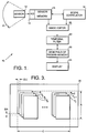
- Fig. 1 is a simplified block diagram of the wide field image generation system of the present invention.
- Fig. 2 shows a more detailed block diagram of the wide field image generation system of the present invention.
- Fig. 3 illustrates the manner in which the pixel values from consecutive image frames initially stored in the first and second sensor memory arrays are overlaid in a wide field memory included within the inventive system.
- Fig. 4 illustrates a viewing mode in which pixel data from the wide field memory and from the image frame most recently stored in a sensor memory are simultaneously displayed on a monitor included within a video display.
- Fig. 5 illustrates the manner in which pixel data from scans taken in opposing horizontal directions and differing elevational orientations are stored in the wide field memory.
- Fig. 6 shows a binary memory, equivalent in dimension to the wide field memory, used in a technique to detect the presence of a potential moving object within the field-of-regard.
- Fig. 1 is a simplified block diagram of the wide field image generation system 10 of the present invention.
- the inventive system 10 is operative to produce an image of a scene within a wide field-of-regard F.
- the system 10 may be disposed within, for example, a missile or other projectile to facilitate navigation thereof.
- successive frames of overlapping image intensity data from a gimbal scanned sensor 12 are sampled by an analog-to-digital converter (A/D) 14 and stored in a sensor memory 16.
- a scene correlator 18 generates a set of offset parameters indicative of the spatial relationship between the successive image frames stored in the sensor memory 16 and registers the successive image frames of sampled data in accordance therewith.
- sampled data pixels
- a temporal filter 22 to selectively average the data to eliminate seams in the display 24.
- An additional feature is supplied by an image editor 26, which may be utilized to remove nonuniformities from the sampled image frames induced by, for example, imperfections in the sensor 12.
- Fig. 2 shows a more detailed block diagram of the wide field image generation system 10 of the present invention.
- the sensor 12 operates to provide analog image information to the A/D converter 14 as the sensor 12 is horizontally panned through the wide field-of-regard F (Fig. 1).
- the sensor 12 will preferably be realized by a two-dimensional focal plane array mounted on a gimbal scan mechanism, other sensor arrangements capable of collecting video data from across the field-of-regard F may be substituted therefor.
- the sensor 12 is chosen to have a field of view substantially narrower than the field-of-regard F - thereby allowing the sensor 12 to be of relatively high resolution.
- the analog image data produced by the sensor 12 corresponds to distinct image frames within the field-of-regard.
- the senor 12 takes "snapshots" of the portion of the scene (not shown) within the field of view thereof at a known rate (e.g. 60 Hz).
- the rate of angular rotation (in azimuth) of the sensor 12 through the field-of-regard F is chosen such that a substantial portion of adjacent image frames spatially overlap.
- the sensor memory 16 includes first and second sensor memory arrays 28 and 30 connected to the A/D 14 converter via an electronic switch 32. Pixel values (digitized image data) from consecutive image frames are alternately read into the arrays 28 and 30 by changing the state of the switch 32. Specifically, if pixel values from a first image frame are read into the first array 28, then pixel values from a second image frame are read into the second array 30. Pixel values from a third image frame would then replace the pixel values from the first frame stored in the first array 28.
- the scene correlator 18 implements a correlation algorithm to generate offset parameters indicative of the spatial relationship between the image frames associated with the pixel values stored in the first and second arrays 28 and 30. It is noted that consecutive image frames may be spatially displaced both horizontally and vertically within the field-of-regard if, for example, the system 10 of the present invention is mounted on a moving vehicle.
- the correlator 18 will typically employ an iterative convolution procedure to determine the offset parameters between the first and second memory arrays 28 and 30.
- the correlator 18 is operative to ascertain the number of rows and columns the second array 30 should be offset from the first such that when the displaced arrays are overlaid in the wide field-of-regard memory 20 the number of wide field memory locations having a common pixel value is maximized.
- the offset parameters produced by the correlator mirror the spatial displacement between the image frames corresponding to the pixel values stored in the arrays 28 and 30.
- the correlator 18 does not rely on information pertaining to the orientation of the gimbal scan mechanism within the field-of-regard in generating the offset parameters, complete uniformity in the angular velocity of the sensor 12 is not required. In contrast, in conventional gimbal scanned imagers it is typically necessary to employ a complex servo system to precisely control the scan rate.
- the image correlator 18 may be realized using a number of techniques familiar to those skilled in the art. One such technique is disclosed by Ichida, et al. in U. S. Patent No. 4,220,967, entitled “Scene Tracker Using Multiple Independent Correlators", issued September 2, 1980, the teachings of which are incorporated herein by reference.
- the scene correlator registers the image data on a field basis by estimating the relative horizontal and vertical offsets between fields during gimbal scan motion. If frame imagery is used to generate the wide field-of-regard image, then the individual fields are correlated and interlaced to form frame segments.
- Correlation is also performed between frames in order to register these segments in memory. For example, assume the pixel value from a first image frame is located in the first row and column of the first array 28, and is assigned to memory location P(i,j) within wide field memory 20. Next assume that the correlator 18 indicates that the image frame stored in the second array 30 should be offset down two additional rows and over two additional columns from the image frame stored in the first array 28. The pixel value from the next (second) image frame located in the first row and column of the second array 30 would then be assigned to memory location P(i+2,j+2) in the wide field memory 20 by the image editor 26 as discussed below. Thus, the coordinates of each modified pixel location are ultimately passed to the wide field memory 20.
- the image editor 26 uses the row and column offset parameters generated by the scene correlator 18 to appropriately overlay, in the wide field memory 20, consecutive frames of pixel values temporarily stored in the sensor memory 16.
- the editor 26 also removes from the arrays 28 and 30 pixel values corresponding to, for example, the periphery of the field of view of the sensor 12.
- Such "edge data" may be distorted either as a result of the proximity of certain detectors to the periphery of the focal plane array within the sensor 12, or as a result of noise associated with scanning the sensor 12.
- the image editor 26 may be implemented with digital circuitry by way of example.
- Fig. 3 illustrates the manner in which the pixel values from consecutive image frames initially stored in the sensor memory arrays 28 and 30 are overlaid in the wide field memory 20.
- frames of pixel data P1 through P n are sequentially stored within the memory 20 as the sensor 12 is panned through the field-of-regard. It is observed that frame P2 is offset from frame P1 by ⁇ R rows and ⁇ C columns within the memory 20, with ⁇ R and ⁇ C being proportional to the offset parameters generated by the scene correlator 18.
- the overlaid frames of pixel data P1 through P n spanning the field-of-regard occupy C columns and R rows within the wide field memory 20.
- the pixel value held by each location in the wide field memory 20 is initialized to -1.
- the presence of a -1 at a location within the memory 20 indicates that image data from the portion of the field-of-regard associated therewith has not yet been collected.
- the image editor 26 serially passes (as indicated by the data path 34) these pixel values to the temporal filter 22.
- the temporal filter 22 reads (path 36) the pixel value stored in the memory 20 at the location assigned to the pixel value last transmitted to the filter 22 along path 34.
- This pixel value will be assumed to be assigned to location (i,j) within the memory 20 and will be denoted as I(i,j).
- I(i,j) As indicated by a pixel test block 38, if the pixel value retrieved from the memory 20 via the path 36 is a -1 then I(i,j) is placed directly into the memory 20 at location (i,j) by way of a data path 40.
- the pixel test block 38 may be implemented with, for example, a comparator and data register.
- the assigned pixel value I(i,j) is sent (path 42) to a first multiplier 44.
- the multiplier 44 may be realized by a look up table, and is operative to multiply the assigned pixel value I(i,j) by the quantity (1-a) where "a" is an adjustable filter coefficient.
- the location (i,j) within the memory 20 is also linked to a second multiplier 46 by a path 48.
- the multiplier 46 may also be realized by a lookup table, and operates to multiply the pixel value P(n,i,j) currently occupying location (i,j) by the filter coefficient "a".
- the pixel values (1-a)I(i,j) and aP(n,i,j) generated by the multipliers 44 and 46 are then added by a summer 50 to create a combined weighted (filtered) pixel value denoted by P(n+1,i,j).
- the parameter "a” will typically be adjusted by modification of the software associated with the look up tables used to realize the multipliers 44 and 46. This filtering process also contributes to an improvement in the signal-to-noise ratio at each pixel location within the memory 20.
- ⁇ SNR (1-a2)/(1-a)2
- the improvement in SNR is approximately 3:1. Improvement in the SNR at locations within the memory 20 enhances the clarity of the wide field image provided by the display 24.
- the temporal filter 22 operates to substantially prevent "seams" from developing between the individual image frames utilized to synthesize the composite wide field image. That is, were pixel data I(i,j) inserted into the memory 20 by merely replacing the preexisting pixel data P(n,i,j) such seams (differences in brightness between adjacent image frames) could potentially appear in the displayed wide field image. Differences in brightness between consecutive frames may occur due to, for example, noise associated with scanning the sensor 12 or the operation of automatic gain control circuitry.
- the unity gain of the filter 22 allows the filtered pixel values to be immediately inserted into the memory 20 without undergoing a scaling operation.
- the filter 22 is of the infinite impulse response (IIR) variety, which reduces memory and computational requirements relative to finite impulse response (FIR) designs. That is, in certain FIR filter implementations the inclusion of a large number of pixel values in the filtering process may impede the efficacy thereof.
- IIR filters may be synthesized from a desired filter function by finding the impulse transfer function ("z" transform) thereof. The terms within the z transform are then realized either in hardware or software.
- the number of pixel values that are computed and processed for each location in memory 20 is a function of the gimbal scan rate and does not adversely affect performance.
- the display 24 is operatively coupled to the wide field memory 20.
- the display 24 may constitute a conventional television monitor or a display typically used with conventional infrared imagers (such as the RS-170, having 525 horizontal lines).
- image data may be provided to the display 24 immediately upon being stored in the memory 20.
- the memory 20 is reinitialized (a -1 is placed in each memory location) at the end of each left to right scan.
- the memory 20 is filled with pixel data in the manner discussed above with reference to the left to right scan. Again, at the conclusion of each left to right scan the memory 20 will be reinitialized prior to commencing the next left to right scan.
- a supplementary wide field memory (not shown) is utilized to store pixel data collected during right to left scanning, while the wide field memory 20 serves to store pixel values collected during left to right scanning.
- both the supplementary memory and the memory 20 would be initialized by placing a -1 in each location.
- the pixel data accumulated in the memory 20 would be supplied to the display 24.
- the memory 20 would not be reinitialized, and the sensor 12 would begin a right to left scan with the data therefrom being stored in the supplementary memory.
- the display 24 would be driven by data within the supplementary memory.
- the display 24 would again be connected to the memory 20 and neither the memory 20 nor the supplementary memory would be reinitialized.
- Fig. 4 illustrates a viewing mode in which pixel data from the wide field memory 20 and from the image frame most recently stored in sensor memory 16 are simultaneously displayed on a monitor 56 included within the display 24.
- a wide field image W and a "live" image L are displayed on the monitor 56.
- the wide field image W is formed as described above on the basis of the pixel values within the memory 20, while the live image L is created by displaying the unfiltered pixel data from the last image stored in the memory 16.
- symbology markers M1 and M2 are used to demarcate the location of the live image within the field-of-regard.
- the markers M1 and M2 may be generated by reference to the instantaneous angular orientation of the sensor 12.
- the markers M1 and M2 can be manually controlled by an operator to select a reference frame (again defined by symbology markers M1 and M2) within the wide field image W.
- the pixel data giving rise to the reference frame within the wide field image W is then contemporaneously displayed in the form of the image L.
- the symbology markers may be manually translated with the assistance of, for example, a dial sensor with an accompanying software driver.
- the sensor 12 may be redirected in the elevational dimension at the conclusion of selected horizontal scans.
- the elevational angle of the sensor 12 may be increased at the conclusion of each left to right scan and decreased by the same amount at the conclusion of each right to left scan to augment the vertical (elevational) dimension of the field-of-regard.
- the sensor 12 is oriented in the elevational dimension such that pixel data from a left to right scan across a lower portion of an augmented field-of-regard is stored in the block of memory locations L R .
- the elevational angle of the sensor 12 is increased, and pixel values from the ensuing right to left scan are stored in the block of memory locations R L .
- a second scene correlator (not shown) will be employed to generate offset parameters enabling registration of blocks L R and R L within the memory 20.
- the correlator 18' could be operative to correlate the last frame of pixel values in block L R with the first pixel value frame within the block R L to generate an elevational offset parameter.
- This offset parameter would be proportional to the number of rows ( ⁇ R') which the blocks R L and L R should be separated in the memory 20.
- the technique described with reference to Fig. 5 may be utilized to create a "downrange map" of a scene within the augmented field-of-regard.
- the present invention may be employed to detect the presence of a potential moving object within the field-of-regard.
- Fig. 6 shows a binary memory 200 equivalent in dimension to the memory 20.
- Each location in the memory 200 is identified with one companion location in the memory 20.
- At the commencement of scanning each location within the memory 200 is initialized to zero. If an object is in motion within the field-of-regard, then pixel values within the memory 20 associated with regions in the field-of-regard in the path of the moving object will change over time. This condition may be detected by placing a "1" in the companion locations in memory 200 associated with locations in the memory 20 having pixels which change in value in excess of a threshold amount between scans.
- the threshold change which must be exceeded to generate a "1" in the memory 200 will be a function of the filter parameter "a” and the gimbal scan rate.
- the direction of motion of the potential moving object can be discerned with knowledge of the instantaneous gimbal scan direction and the manner in which the 1's appear within the memory 200. For example, if the gimbal is scanning left to right and the object under surveillance is moving from right to left within the field-of-regard then the row of 1's shown in Fig. 6 will appear from right to left in time. Similarly, if the sensor scan is left to right and the object is moving from left to right, then the row of 1's will appear from left to right as a function of time. A similar analysis may be applied to ascertain the rate of motion to the extent that the scan rate and the rate at which the 1's appear in the memory 200 are known.
- the inventive wide field image generation system is not limited to a particular sensor scanning arrangement. Any sensing device capable of providing a sequence of framed image data may be used in the manner disclosed herein.
- the present invention is not limited to embodiments employing the aforementioned temporal filter to process pixel data prior to storage in a wide field memory. Those skilled in the art may be aware of other schemes suggested by the teachings herein for enhancing the continuity of the composite wide field image.
Landscapes
- Engineering & Computer Science (AREA)
- Multimedia (AREA)
- Signal Processing (AREA)
- Image Processing (AREA)
- Television Systems (AREA)
- Transforming Light Signals Into Electric Signals (AREA)
- Closed-Circuit Television Systems (AREA)
- Studio Circuits (AREA)
- Image Input (AREA)
Applications Claiming Priority (2)
| Application Number | Priority Date | Filing Date | Title |
|---|---|---|---|
| US783746 | 1991-10-28 | ||
| US07/783,746 US5321798A (en) | 1991-10-28 | 1991-10-28 | Apparatus for providing a composite digital representation of a scene within a field-of-regard |
Publications (3)
| Publication Number | Publication Date |
|---|---|
| EP0539897A2 true EP0539897A2 (fr) | 1993-05-05 |
| EP0539897A3 EP0539897A3 (en) | 1993-07-07 |
| EP0539897B1 EP0539897B1 (fr) | 1997-07-30 |
Family
ID=25130270
Family Applications (1)
| Application Number | Title | Priority Date | Filing Date |
|---|---|---|---|
| EP92118256A Expired - Lifetime EP0539897B1 (fr) | 1991-10-28 | 1992-10-26 | Système de production d'images à large champ |
Country Status (12)
| Country | Link |
|---|---|
| US (1) | US5321798A (fr) |
| EP (1) | EP0539897B1 (fr) |
| JP (1) | JPH05304676A (fr) |
| KR (1) | KR960014330B1 (fr) |
| AU (1) | AU647975B2 (fr) |
| CA (1) | CA2076233A1 (fr) |
| DE (1) | DE69221258T2 (fr) |
| ES (1) | ES2106117T3 (fr) |
| GR (1) | GR3025203T3 (fr) |
| IL (1) | IL103430A (fr) |
| NO (1) | NO924139L (fr) |
| TR (1) | TR27471A (fr) |
Cited By (6)
| Publication number | Priority date | Publication date | Assignee | Title |
|---|---|---|---|---|
| GB2281468A (en) * | 1993-08-12 | 1995-03-01 | Israel State | Apparatus for enlarging the field of view of observation systems |
| DE19782037C2 (de) * | 1996-09-30 | 2003-02-06 | Intel Corp | Verfahren und Einrichtung zur Erzeugung eines zusammengesetzten Bildes |
| EP1597913A4 (fr) * | 2003-02-17 | 2007-04-18 | Silverbrook Res Pty Ltd | Detecteur d'image avec stockage de trames numerique |
| WO2007053075A3 (fr) * | 2005-11-04 | 2007-06-28 | Autoliv Dev | Systeme de vision infrarouge et procede d'amelioration d'images |
| US8045011B2 (en) | 2005-11-04 | 2011-10-25 | Autoliv Development Ab | Imaging apparatus |
| US8416468B2 (en) | 1999-09-17 | 2013-04-09 | Silverbrook Research Pty Ltd | Sensing device for subsampling imaged coded data |
Families Citing this family (4)
| Publication number | Priority date | Publication date | Assignee | Title |
|---|---|---|---|---|
| US6205259B1 (en) * | 1992-04-09 | 2001-03-20 | Olympus Optical Co., Ltd. | Image processing apparatus |
| US5463729A (en) * | 1992-09-21 | 1995-10-31 | Matsushita Electric Industrial Co., Ltd. | Image generation device |
| JPH11296666A (ja) * | 1998-02-16 | 1999-10-29 | Sony Corp | 画像接続方法、画像接続装置、並びに、画像接続処理プログラムが格納された記録媒体 |
| JP2004534963A (ja) * | 2001-03-30 | 2004-11-18 | コーニンクレッカ フィリップス エレクトロニクス エヌ ヴィ | 強化現実のための方法、システム及び装置 |
Family Cites Families (11)
| Publication number | Priority date | Publication date | Assignee | Title |
|---|---|---|---|---|
| US4400727A (en) * | 1981-11-27 | 1983-08-23 | The Bendix Corporation | Moving map display |
| JPS60111640A (ja) * | 1983-11-21 | 1985-06-18 | 横河メディカルシステム株式会社 | 画像再構成装置 |
| AU579441B2 (en) * | 1985-01-16 | 1988-11-24 | Mitsubishi Denki Kabushiki Kaisha | Video encoding apparatus |
| US4673988A (en) * | 1985-04-22 | 1987-06-16 | E.I. Du Pont De Nemours And Company | Electronic mosaic imaging process |
| US4845641A (en) * | 1986-09-19 | 1989-07-04 | Hoya Corporation | Method of forming a synthetic image in simulation system for attachment of spectacles |
| US4743970A (en) * | 1986-10-20 | 1988-05-10 | The Grass Valley Group, Inc. | Picture transformation memory |
| US4873657A (en) * | 1987-11-13 | 1989-10-10 | The United States Of America As Represented By The Secretary Of The Army | Method for simulating an image by correllation |
| JP2615703B2 (ja) * | 1987-11-20 | 1997-06-04 | 富士通株式会社 | 捜索型撮像装置 |
| JP2720974B2 (ja) * | 1988-03-31 | 1998-03-04 | キヤノン株式会社 | 画像情報処理装置 |
| JPH02226984A (ja) * | 1989-02-28 | 1990-09-10 | Toshiba Corp | 画像データ処理装置 |
| JP2766316B2 (ja) * | 1989-06-09 | 1998-06-18 | 株式会社東芝 | X線診断装置 |
-
1991
- 1991-10-28 US US07/783,746 patent/US5321798A/en not_active Expired - Lifetime
-
1992
- 1992-08-17 CA CA002076233A patent/CA2076233A1/fr not_active Abandoned
- 1992-10-14 IL IL103430A patent/IL103430A/xx active IP Right Review Request
- 1992-10-21 TR TR01079/92A patent/TR27471A/xx unknown
- 1992-10-21 AU AU27237/92A patent/AU647975B2/en not_active Expired
- 1992-10-26 ES ES92118256T patent/ES2106117T3/es not_active Expired - Lifetime
- 1992-10-26 EP EP92118256A patent/EP0539897B1/fr not_active Expired - Lifetime
- 1992-10-26 DE DE69221258T patent/DE69221258T2/de not_active Expired - Lifetime
- 1992-10-27 NO NO92924139A patent/NO924139L/no unknown
- 1992-10-27 KR KR1019920019791A patent/KR960014330B1/ko not_active Expired - Fee Related
- 1992-10-28 JP JP4290470A patent/JPH05304676A/ja active Pending
-
1997
- 1997-10-29 GR GR970402839T patent/GR3025203T3/el unknown
Cited By (7)
| Publication number | Priority date | Publication date | Assignee | Title |
|---|---|---|---|---|
| GB2281468A (en) * | 1993-08-12 | 1995-03-01 | Israel State | Apparatus for enlarging the field of view of observation systems |
| DE19782037C2 (de) * | 1996-09-30 | 2003-02-06 | Intel Corp | Verfahren und Einrichtung zur Erzeugung eines zusammengesetzten Bildes |
| US8416468B2 (en) | 1999-09-17 | 2013-04-09 | Silverbrook Research Pty Ltd | Sensing device for subsampling imaged coded data |
| EP1597913A4 (fr) * | 2003-02-17 | 2007-04-18 | Silverbrook Res Pty Ltd | Detecteur d'image avec stockage de trames numerique |
| US8023020B2 (en) | 2003-02-17 | 2011-09-20 | Silverbrook Research Pty Ltd. | Pixel sensor with voltage compensator |
| WO2007053075A3 (fr) * | 2005-11-04 | 2007-06-28 | Autoliv Dev | Systeme de vision infrarouge et procede d'amelioration d'images |
| US8045011B2 (en) | 2005-11-04 | 2011-10-25 | Autoliv Development Ab | Imaging apparatus |
Also Published As
| Publication number | Publication date |
|---|---|
| DE69221258T2 (de) | 1997-11-27 |
| NO924139D0 (no) | 1992-10-27 |
| EP0539897A3 (en) | 1993-07-07 |
| US5321798A (en) | 1994-06-14 |
| EP0539897B1 (fr) | 1997-07-30 |
| NO924139L (no) | 1993-04-29 |
| ES2106117T3 (es) | 1997-11-01 |
| KR960014330B1 (ko) | 1996-10-15 |
| IL103430A (en) | 1997-07-13 |
| JPH05304676A (ja) | 1993-11-16 |
| AU647975B2 (en) | 1994-03-31 |
| KR930009348A (ko) | 1993-05-22 |
| IL103430A0 (en) | 1994-08-26 |
| CA2076233A1 (fr) | 1993-04-29 |
| TR27471A (tr) | 1995-06-01 |
| GR3025203T3 (en) | 1998-02-27 |
| DE69221258D1 (de) | 1997-09-04 |
| AU2723792A (en) | 1993-04-29 |
Similar Documents
| Publication | Publication Date | Title |
|---|---|---|
| EP0534438B1 (fr) | Système de prise d'images à grand champ de vision | |
| US6738073B2 (en) | Camera system with both a wide angle view and a high resolution view | |
| EP0599470B1 (fr) | Systèmes de caméra panoramique | |
| JP3518689B2 (ja) | カメラ画像からのスタジオカメラ位置及び移動の導出 | |
| US5060074A (en) | Video imaging apparatus | |
| US9398214B2 (en) | Multiple view and multiple object processing in wide-angle video camera | |
| US20020075258A1 (en) | Camera system with high resolution image inside a wide angle view | |
| EP2359604B1 (fr) | Modification d'une image cfa à canal panchromatique et en couleurs | |
| US5920657A (en) | Method of creating a high resolution still image using a plurality of images and apparatus for practice of the method | |
| US7760965B2 (en) | Extended range image processing for electro-optical systems | |
| US20020063711A1 (en) | Camera system with high resolution image inside a wide angle view | |
| US20130021434A1 (en) | Method and System of Simultaneously Displaying Multiple Views for Video Surveillance | |
| JPH0364908B2 (fr) | ||
| EP0539897B1 (fr) | Système de production d'images à large champ | |
| EP0354067A2 (fr) | Détecteur de différence spectrale dans l'infrarouge | |
| JPH05161145A (ja) | 面順次撮像装置 | |
| JPH06209926A (ja) | X線動画像撮影装置 | |
| US5023719A (en) | Imaging system for providing multiple simultaneous real time images | |
| GB2275842A (en) | Automatic image stabilizing system for a camcorder | |
| US20010030696A1 (en) | Color video camera system and method with optical prefilter | |
| EP0673575B1 (fr) | Signaux video de haute definition obtenus a partir de sources de basse definition | |
| GB2249897A (en) | Multiple simultaneous real-time imaging with selected magnified portions | |
| JP3310189B2 (ja) | テレビジョン画面の撮影方法および映像合成装置 | |
| JPS6094588A (ja) | カラ−ビデオカメラ装置 | |
| JPH06217328A (ja) | カラー撮像装置 |
Legal Events
| Date | Code | Title | Description |
|---|---|---|---|
| PUAI | Public reference made under article 153(3) epc to a published international application that has entered the european phase |
Free format text: ORIGINAL CODE: 0009012 |
|
| AK | Designated contracting states |
Kind code of ref document: A2 Designated state(s): CH DE ES FR GB GR IT LI NL SE |
|
| PUAL | Search report despatched |
Free format text: ORIGINAL CODE: 0009013 |
|
| AK | Designated contracting states |
Kind code of ref document: A3 Designated state(s): CH DE ES FR GB GR IT LI NL SE |
|
| 17P | Request for examination filed |
Effective date: 19940104 |
|
| 17Q | First examination report despatched |
Effective date: 19951130 |
|
| GRAG | Despatch of communication of intention to grant |
Free format text: ORIGINAL CODE: EPIDOS AGRA |
|
| GRAH | Despatch of communication of intention to grant a patent |
Free format text: ORIGINAL CODE: EPIDOS IGRA |
|
| GRAH | Despatch of communication of intention to grant a patent |
Free format text: ORIGINAL CODE: EPIDOS IGRA |
|
| GRAA | (expected) grant |
Free format text: ORIGINAL CODE: 0009210 |
|
| AK | Designated contracting states |
Kind code of ref document: B1 Designated state(s): CH DE ES FR GB GR IT LI NL SE |
|
| REG | Reference to a national code |
Ref country code: CH Ref legal event code: NV Representative=s name: ISLER & PEDRAZZINI AG Ref country code: CH Ref legal event code: EP |
|
| REF | Corresponds to: |
Ref document number: 69221258 Country of ref document: DE Date of ref document: 19970904 |
|
| PGFP | Annual fee paid to national office [announced via postgrant information from national office to epo] |
Ref country code: FR Payment date: 19970910 Year of fee payment: 6 |
|
| PGFP | Annual fee paid to national office [announced via postgrant information from national office to epo] |
Ref country code: SE Payment date: 19970918 Year of fee payment: 6 |
|
| PGFP | Annual fee paid to national office [announced via postgrant information from national office to epo] |
Ref country code: NL Payment date: 19970923 Year of fee payment: 6 |
|
| PGFP | Annual fee paid to national office [announced via postgrant information from national office to epo] |
Ref country code: GR Payment date: 19970926 Year of fee payment: 6 |
|
| PGFP | Annual fee paid to national office [announced via postgrant information from national office to epo] |
Ref country code: CH Payment date: 19971002 Year of fee payment: 6 |
|
| PGFP | Annual fee paid to national office [announced via postgrant information from national office to epo] |
Ref country code: ES Payment date: 19971008 Year of fee payment: 6 |
|
| ET | Fr: translation filed | ||
| ITF | It: translation for a ep patent filed | ||
| REG | Reference to a national code |
Ref country code: ES Ref legal event code: FG2A Ref document number: 2106117 Country of ref document: ES Kind code of ref document: T3 |
|
| REG | Reference to a national code |
Ref country code: GR Ref legal event code: FG4A Free format text: 3025203 |
|
| PLBE | No opposition filed within time limit |
Free format text: ORIGINAL CODE: 0009261 |
|
| STAA | Information on the status of an ep patent application or granted ep patent |
Free format text: STATUS: NO OPPOSITION FILED WITHIN TIME LIMIT |
|
| 26N | No opposition filed | ||
| PG25 | Lapsed in a contracting state [announced via postgrant information from national office to epo] |
Ref country code: SE Free format text: LAPSE BECAUSE OF NON-PAYMENT OF DUE FEES Effective date: 19981027 Ref country code: ES Free format text: THE PATENT HAS BEEN ANNULLED BY A DECISION OF A NATIONAL AUTHORITY Effective date: 19981027 |
|
| PG25 | Lapsed in a contracting state [announced via postgrant information from national office to epo] |
Ref country code: GR Free format text: LAPSE BECAUSE OF NON-PAYMENT OF DUE FEES Effective date: 19981031 Ref country code: LI Free format text: LAPSE BECAUSE OF NON-PAYMENT OF DUE FEES Effective date: 19981031 Ref country code: CH Free format text: LAPSE BECAUSE OF NON-PAYMENT OF DUE FEES Effective date: 19981031 |
|
| REG | Reference to a national code |
Ref country code: GB Ref legal event code: 732E |
|
| PG25 | Lapsed in a contracting state [announced via postgrant information from national office to epo] |
Ref country code: NL Free format text: LAPSE BECAUSE OF NON-PAYMENT OF DUE FEES Effective date: 19990501 |
|
| REG | Reference to a national code |
Ref country code: CH Ref legal event code: PL |
|
| EUG | Se: european patent has lapsed |
Ref document number: 92118256.4 |
|
| PG25 | Lapsed in a contracting state [announced via postgrant information from national office to epo] |
Ref country code: FR Free format text: LAPSE BECAUSE OF NON-PAYMENT OF DUE FEES Effective date: 19990630 |
|
| NLV4 | Nl: lapsed or anulled due to non-payment of the annual fee |
Effective date: 19990501 |
|
| REG | Reference to a national code |
Ref country code: FR Ref legal event code: ST |
|
| REG | Reference to a national code |
Ref country code: ES Ref legal event code: FD2A Effective date: 20001204 |
|
| REG | Reference to a national code |
Ref country code: GB Ref legal event code: IF02 |
|
| PG25 | Lapsed in a contracting state [announced via postgrant information from national office to epo] |
Ref country code: IT Free format text: LAPSE BECAUSE OF NON-PAYMENT OF DUE FEES Effective date: 20051026 |
|
| PGFP | Annual fee paid to national office [announced via postgrant information from national office to epo] |
Ref country code: DE Payment date: 20101020 Year of fee payment: 19 |
|
| PGFP | Annual fee paid to national office [announced via postgrant information from national office to epo] |
Ref country code: GB Payment date: 20101020 Year of fee payment: 19 |
|
| REG | Reference to a national code |
Ref country code: DE Ref legal event code: R071 Ref document number: 69221258 Country of ref document: DE |
|
| REG | Reference to a national code |
Ref country code: DE Ref legal event code: R071 Ref document number: 69221258 Country of ref document: DE |
|
| REG | Reference to a national code |
Ref country code: GB Ref legal event code: PE20 Expiry date: 20121025 |
|
| PG25 | Lapsed in a contracting state [announced via postgrant information from national office to epo] |
Ref country code: GB Free format text: LAPSE BECAUSE OF EXPIRATION OF PROTECTION Effective date: 20121025 |
|
| REG | Reference to a national code |
Ref country code: GB Ref legal event code: 732E Free format text: REGISTERED BETWEEN 20130912 AND 20130918 |