EP0540004A1 - Mécanisme pour ajuster ensemble des éléments de moule dans un dispositif de moulage sous pression - Google Patents
Mécanisme pour ajuster ensemble des éléments de moule dans un dispositif de moulage sous pression Download PDFInfo
- Publication number
- EP0540004A1 EP0540004A1 EP92118544A EP92118544A EP0540004A1 EP 0540004 A1 EP0540004 A1 EP 0540004A1 EP 92118544 A EP92118544 A EP 92118544A EP 92118544 A EP92118544 A EP 92118544A EP 0540004 A1 EP0540004 A1 EP 0540004A1
- Authority
- EP
- European Patent Office
- Prior art keywords
- molding
- wedge
- flasks
- flask
- shaped abutting
- Prior art date
- Legal status (The legal status is an assumption and is not a legal conclusion. Google has not performed a legal analysis and makes no representation as to the accuracy of the status listed.)
- Withdrawn
Links
- 238000000465 moulding Methods 0.000 title claims abstract description 123
- 230000013011 mating Effects 0.000 title claims abstract description 15
- 239000002775 capsule Substances 0.000 claims description 6
- 238000000034 method Methods 0.000 abstract description 3
- 238000005266 casting Methods 0.000 description 4
- 238000007796 conventional method Methods 0.000 description 2
- 238000004519 manufacturing process Methods 0.000 description 2
- 238000010276 construction Methods 0.000 description 1
- 230000008021 deposition Effects 0.000 description 1
- 238000003780 insertion Methods 0.000 description 1
- 230000037431 insertion Effects 0.000 description 1
- 238000005304 joining Methods 0.000 description 1
- 239000000463 material Substances 0.000 description 1
- 229910052573 porcelain Inorganic materials 0.000 description 1
- 229920003002 synthetic resin Polymers 0.000 description 1
- 239000000057 synthetic resin Substances 0.000 description 1
Images


Classifications
-
- B—PERFORMING OPERATIONS; TRANSPORTING
- B28—WORKING CEMENT, CLAY, OR STONE
- B28B—SHAPING CLAY OR OTHER CERAMIC COMPOSITIONS; SHAPING SLAG; SHAPING MIXTURES CONTAINING CEMENTITIOUS MATERIAL, e.g. PLASTER
- B28B7/00—Moulds; Cores; Mandrels
- B28B7/0002—Auxiliary parts or elements of the mould
- B28B7/0011—Mould seals
-
- B—PERFORMING OPERATIONS; TRANSPORTING
- B28—WORKING CEMENT, CLAY, OR STONE
- B28B—SHAPING CLAY OR OTHER CERAMIC COMPOSITIONS; SHAPING SLAG; SHAPING MIXTURES CONTAINING CEMENTITIOUS MATERIAL, e.g. PLASTER
- B28B1/00—Producing shaped prefabricated articles from the material
- B28B1/26—Producing shaped prefabricated articles from the material by slip-casting, i.e. by casting a suspension or dispersion of the material in a liquid-absorbent or porous mould, the liquid being allowed to soak into or pass through the walls of the mould; Moulds therefor ; specially for manufacturing articles starting from a ceramic slip; Moulds therefor
- B28B1/261—Moulds therefor
-
- B—PERFORMING OPERATIONS; TRANSPORTING
- B28—WORKING CEMENT, CLAY, OR STONE
- B28B—SHAPING CLAY OR OTHER CERAMIC COMPOSITIONS; SHAPING SLAG; SHAPING MIXTURES CONTAINING CEMENTITIOUS MATERIAL, e.g. PLASTER
- B28B1/00—Producing shaped prefabricated articles from the material
- B28B1/26—Producing shaped prefabricated articles from the material by slip-casting, i.e. by casting a suspension or dispersion of the material in a liquid-absorbent or porous mould, the liquid being allowed to soak into or pass through the walls of the mould; Moulds therefor ; specially for manufacturing articles starting from a ceramic slip; Moulds therefor
- B28B1/265—Producing shaped prefabricated articles from the material by slip-casting, i.e. by casting a suspension or dispersion of the material in a liquid-absorbent or porous mould, the liquid being allowed to soak into or pass through the walls of the mould; Moulds therefor ; specially for manufacturing articles starting from a ceramic slip; Moulds therefor pressure being applied on the slip in the filled mould or on the moulded article in the mould, e.g. pneumatically, by compressing slip in a closed mould
- B28B1/266—Means for counteracting the pressure being applied on the slip or on the moulded article in the mould, e.g. means for clamping the moulds parts together in a frame-like structure
Definitions
- the present invention relates to a molding flask mating mechanism for cast molding a slip under pressure and molding green articles of sanitary ware or the like, before being fired.
- the sanitary ware represented by stool ware and wash basin is produced in such a manner that green articles are molded by cast molding a slip of muddy materials and then fired in a kiln.
- the technique of cast molding the slip under pressure has hitherto been well known as disclosed in, for example, EP-A-352056, EP-A-389234, GB-A-792351, JP-A Sho 63-288705, JP-A Hei 3-69313, JP-A Hei 3-67604, JP-A Hei 3-69304, JP-A Hei 3-81103, JP-A Hei 3-67605, and JP-A Hei 3-83608.
- a mating and positioning mechanism as shown in Figs. 11 and 12 has hitherto been used during the joining of the molding flasks with each other.
- left and right molding flasks 3, 4 as well as upper and lower molding flasks 5, 7 composed of porous bodies and metallic capsules are provided with projecting knock pins 6, and knock pin bores 19 are bored in the positions at opposite molding flasks respectively, so that both the lateral molding flasks and the vertical ones are mated to be positioned.
- the present invention aims at solving the above problem.
- a molding flask transportation line 11 is disposed at the right side and a green article transportation line 12 at the left side.
- Pressure cast producing apparatus are disposed at an intermediate portion between the molding flask transportation line 11 and the green article transportation line 12.
- Each pressure cast producing apparatus comprises a pressurized machine casing 2.
- a slip stand A for supplying a slip to the pressure cast producing apparatus is attached to each pressure cast producing apparatus.
- the molding stations each comprise the pressurized machine casing 2 and slip stand A.
- a casting mold transported on the casting mold transportation line 11 is transported to the molding station so as to be fixedly disposed from a casting mold branch line 32 which leads to the inside of the pressurized machine casing 2.
- the molding flask transportation line 11b is divided into a molding flask transportation line 11a and a green article branch line 13, so that it is decided by discriminating the part number of molding flask whether the molding flask enters into a green article branch line 13 or directly passes the molding flask transportation line 11a to reach a molding flask housing line.
- each pressurized machine casing 2 there is fixed a whole molding flask comprising left and right molding flasks 3, 4 as well as upper and lower ones 5, 7, the left and right molding flasks 3, 4 being urged by left and right urging cylinders 15, 16 and the upper and lower molding flasks 5, 7 being urged by upper and lower urging cylinders 14, 17.
- the four molding flasks are urged from four directions to be one molding flask and thereafter the pressurized slip is charged therein so that the slip is deposited onto porous bodies at the inner surface of the molding flask.
- the left and right molding flasks 3, 4 as well as upper and lower molding flasks 5, 7 are composed of porous bodies disposed inside the flask and metallic capsules cover the outside thereof.
- a demolding work is carried out inside the pressurized machine casing 2 and a finished green article 1 is transferred to the green article transportation line 12 from the green article branch line 13.
- a slip pressure-feeding pump At the slip stand A there are disposed a slip pressure-feeding pump, a slip temporarily storing tank and the like.
- the molding flask transportation line 11 and the molding flask branch line 32 each have a smaller track width, so that, as shown in Figs. 1(a) and 1(b), the molding flask is put on and transported by a molding flask loading truck 30 having a smaller distance between the wheels.
- a molding flask loading truck 30 having a smaller distance between the wheels.
- the green article 1 is put on a green article loading truck 31 having a larger distance between the wheels travelling on the green article branch line 13 and green article transportation line 12 having a larger width of track.
- Fig. 1(c) shows that the green article 1 after having been molded and demolded is put on the green article loading truck 31.
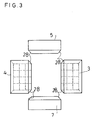
- a casting mold is constructed based on the left and right molding flasks 3, 4 as well as upper and lower molding flasks 5, 7.
- the entire molding flask is urged by the left and right urging cylinders 15, 16 for urging the left and right molding flasks 3, 4 and by the upper and lower urging cylinders 14, 17 for urging the upper and lower flasks 5, 7.
- the four molding flasks of the pair of left and right molding flasks 3, 4 and the pair of upper and lower molding flasks 5, 7 each has therein a porous body and is covered at the outside thereof with a metallic capsule. At the edges on which the porous bodies contact each other in the four molding flasks there are provided long wedge-like shaped abutting portions 28, respectively.
- all the long wedge-like shaped abutting portions 28 are adapted to come into close contact with each other.
- the wedge-like shaped abutting portions 28 in the embodiment are made longer to be wedge-like shaped at all the rectangular edges. As shown in Fig. 4, the left and right molding flasks 3, 4 at first abut against each other through the wedge-like shaped abutting portions 28 as a guide and thereafter the upper and lower molding flasks 5, 7 are positioned vertically and mated by the portions 28 as a guide.
- FIG. 6 a molding flask for constructing a green article 26 for a tank of porcelain, like a low tank, disposed at a flush stool.
- the lower molding flask 23 and the upper molding flask 25 both are composed of inner porous bodies and metallic capsules covering them around, the green article 26 being deposited onto the inner porous bodies.
- Wedge-like shaped abutting portions 9 project upwardly from the upper surface of the lower molding flask 23 and wedge-like shaped abutting portions 8 project downwardly from the lower surface of the upper molding flask 25, so that the upper molding flask 25 and the lower molding flask 23 are completely brought into close contact with each other at the position where both flasks are completely mated in the abutting state.
- exchange type abutting surfaces 8a, 9a are disposed on the abutting surfaces of the wedge-like shaped abutting portion 8 attached to the upper molding flask 25 and of the wedge-like shaped abutting portion 9 attached to the lower molding flask 23, so that, when only the abutting surfaces 8a and 9a are worn, the portions 8 and 9 are exchangeable. Hence, even when the number of times of the use increases, the molding flasks engage with each other always with accuracy.
- the wedge-like shaped abutting portions 8, 9 each are provided with two wedge-like surfaces, whereby the abutting portions 8 and 9 can be collectively disposed at one position.
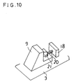
- Fig. 10 shows an embodiment for making the wedge-like shaped abutting portions 8 and 9 fine adjustable in position to each other, in which an adjusting bolt seat 18 and an adjusting bolt 20 are provided at a part of the porous body of the left and right molding flasks 3, 4 so that the wedge-like shaped abutting portion 9 can be fixed by a fixing bolt 21 to the left or right molding flasks 3, 4.
- the fixing bolt 21 is unscrewed and the adjusting bolt 20 is rotated so that the wedge-like shaped abutting portion 9 can be adjusted into a predetermined position and again fixed by the fixing bolt 21.
- the porous bodies composed of synthetic resin are disposed inside the four molding flasks and metallic capsules cover the outside thereof.
- the wedge-like shaped abutting portions 28 are disposed at the entire surfaces of edges abutting against the porous bodies at the molding flask, so that, in the state where the wedge-like shaped abutting portions 28 abut against each other, the molding flasks are completely brought into close contact with each other.
- the wedge-like shaped abutting portion 8 projects from the upper molding flask 25 and the lower wedge-like shaped abutting portion 9 projects from the lower molding flask 23, so that when both abutting portions 8, 9 abut against each other, the upper molding flask 25 and the lower one 23 are adapted to mate each other.
- the present invention has the following advantage. Since the knock pins 6 have hitherto defined the mating position of the molding flask, a gap of allowance is required in the size of each knock pin 6 and knock pin bore 19, so that there is a risk of shifting the molding flasks relative to each other. Contrary to this, the wedge-like shaped abutting portions 8, 9 and the wedge-like shaped portions 28 according to the present invention clearly define and fix the positioning portions, whereby the disadvantage of the conventional technique is eliminated.
Landscapes
- Engineering & Computer Science (AREA)
- Chemical & Material Sciences (AREA)
- Ceramic Engineering (AREA)
- Manufacturing & Machinery (AREA)
- Mechanical Engineering (AREA)
- Dispersion Chemistry (AREA)
- Moulds, Cores, Or Mandrels (AREA)
- Producing Shaped Articles From Materials (AREA)
- Casting Devices For Molds (AREA)
Applications Claiming Priority (2)
| Application Number | Priority Date | Filing Date | Title |
|---|---|---|---|
| JP28182891A JPH05116121A (ja) | 1991-10-29 | 1991-10-29 | 圧力鋳込み成形装置の型枠合わせ機構 |
| JP281828/91 | 1991-10-29 |
Publications (1)
| Publication Number | Publication Date |
|---|---|
| EP0540004A1 true EP0540004A1 (fr) | 1993-05-05 |
Family
ID=17644572
Family Applications (1)
| Application Number | Title | Priority Date | Filing Date |
|---|---|---|---|
| EP92118544A Withdrawn EP0540004A1 (fr) | 1991-10-29 | 1992-10-29 | Mécanisme pour ajuster ensemble des éléments de moule dans un dispositif de moulage sous pression |
Country Status (2)
| Country | Link |
|---|---|
| EP (1) | EP0540004A1 (fr) |
| JP (1) | JPH05116121A (fr) |
Cited By (3)
| Publication number | Priority date | Publication date | Assignee | Title |
|---|---|---|---|---|
| WO1996031329A1 (fr) | 1995-04-04 | 1996-10-10 | S.I.T.I. S.P.A. Societa' Impianti Termoelettrici Industriali | Procede pour former des installations sanitaires de forme compliquee a l'aide d'un module qui comprend quatre parties faites en une resine poreuse et dispositif pour mettre en oeuvre ce procede |
| EP0908283A1 (fr) * | 1997-10-13 | 1999-04-14 | Thuringia Netzsch Feinkeramik GmbH & Co. KG | Installation pour le coulage sous pression d'articles en céramique |
| EP3584049A3 (fr) * | 2018-06-01 | 2020-04-08 | Tools and Technologies GmbH | Machine de moulage en plusieurs pièces |
Citations (12)
| Publication number | Priority date | Publication date | Assignee | Title |
|---|---|---|---|---|
| US1577132A (en) * | 1925-06-27 | 1926-03-16 | Adolph Mueller | Mold for water-closet-bowl rims |
| FR38776E (fr) * | 1929-10-02 | 1931-07-18 | Procédé pour l'obtention de produits bruts dans l'industrie céramique au moyen dematières premières sous pression | |
| FR1161596A (fr) * | 1956-10-31 | 1958-09-02 | Grande Poterie Alsacienne | Presse à mouler pour articles creux en terre cuite |
| FR2109111A5 (fr) * | 1970-10-01 | 1972-05-26 | Perrier Maurice | |
| US3838960A (en) * | 1972-01-21 | 1974-10-01 | Beatrice Foods Co | Apparatus for making injection molded articles |
| US3989795A (en) * | 1973-08-13 | 1976-11-02 | Iowa State University Research Foundation, Inc. | Method of compressing ceramic refractory bodies |
| GB1537746A (en) * | 1975-12-29 | 1979-01-04 | Theysohn F | Mould |
| EP0061072A2 (fr) * | 1981-03-21 | 1982-09-29 | Maschinenfabrik Köppern GmbH. & Co. KG | Moule d'injection |
| GB2099804A (en) * | 1978-04-07 | 1982-12-15 | Inoue Japax Res | Sintering of particulate material |
| EP0211653A1 (fr) * | 1985-08-06 | 1987-02-25 | Inax Corporation | Procédé pour la fabrication de produits creux par coulage et aspiration |
| WO1987002304A1 (fr) * | 1985-10-10 | 1987-04-23 | Uniport Polyester-Formenbau Th. Hirzel | Moule en particulier pour la fabrication de corps en matiere synthetique ou en beton ou mortier melange avec de la matiere synthetique |
| JPS62174121A (ja) * | 1986-01-29 | 1987-07-30 | Honda Motor Co Ltd | キャブレター用ブロックの成形装置 |
Family Cites Families (1)
| Publication number | Priority date | Publication date | Assignee | Title |
|---|---|---|---|---|
| JPS62181102A (ja) * | 1986-02-05 | 1987-08-08 | 株式会社神戸製鋼所 | 泥状セラミツク脱水成形方法 |
-
1991
- 1991-10-29 JP JP28182891A patent/JPH05116121A/ja active Pending
-
1992
- 1992-10-29 EP EP92118544A patent/EP0540004A1/fr not_active Withdrawn
Patent Citations (12)
| Publication number | Priority date | Publication date | Assignee | Title |
|---|---|---|---|---|
| US1577132A (en) * | 1925-06-27 | 1926-03-16 | Adolph Mueller | Mold for water-closet-bowl rims |
| FR38776E (fr) * | 1929-10-02 | 1931-07-18 | Procédé pour l'obtention de produits bruts dans l'industrie céramique au moyen dematières premières sous pression | |
| FR1161596A (fr) * | 1956-10-31 | 1958-09-02 | Grande Poterie Alsacienne | Presse à mouler pour articles creux en terre cuite |
| FR2109111A5 (fr) * | 1970-10-01 | 1972-05-26 | Perrier Maurice | |
| US3838960A (en) * | 1972-01-21 | 1974-10-01 | Beatrice Foods Co | Apparatus for making injection molded articles |
| US3989795A (en) * | 1973-08-13 | 1976-11-02 | Iowa State University Research Foundation, Inc. | Method of compressing ceramic refractory bodies |
| GB1537746A (en) * | 1975-12-29 | 1979-01-04 | Theysohn F | Mould |
| GB2099804A (en) * | 1978-04-07 | 1982-12-15 | Inoue Japax Res | Sintering of particulate material |
| EP0061072A2 (fr) * | 1981-03-21 | 1982-09-29 | Maschinenfabrik Köppern GmbH. & Co. KG | Moule d'injection |
| EP0211653A1 (fr) * | 1985-08-06 | 1987-02-25 | Inax Corporation | Procédé pour la fabrication de produits creux par coulage et aspiration |
| WO1987002304A1 (fr) * | 1985-10-10 | 1987-04-23 | Uniport Polyester-Formenbau Th. Hirzel | Moule en particulier pour la fabrication de corps en matiere synthetique ou en beton ou mortier melange avec de la matiere synthetique |
| JPS62174121A (ja) * | 1986-01-29 | 1987-07-30 | Honda Motor Co Ltd | キャブレター用ブロックの成形装置 |
Non-Patent Citations (1)
| Title |
|---|
| PATENT ABSTRACTS OF JAPAN vol. 12, no. 14 (M-659)(2861) 16 January 1988 & JP-A-62 174 121 ( HONDA MOTOR CO LTD ) * |
Cited By (3)
| Publication number | Priority date | Publication date | Assignee | Title |
|---|---|---|---|---|
| WO1996031329A1 (fr) | 1995-04-04 | 1996-10-10 | S.I.T.I. S.P.A. Societa' Impianti Termoelettrici Industriali | Procede pour former des installations sanitaires de forme compliquee a l'aide d'un module qui comprend quatre parties faites en une resine poreuse et dispositif pour mettre en oeuvre ce procede |
| EP0908283A1 (fr) * | 1997-10-13 | 1999-04-14 | Thuringia Netzsch Feinkeramik GmbH & Co. KG | Installation pour le coulage sous pression d'articles en céramique |
| EP3584049A3 (fr) * | 2018-06-01 | 2020-04-08 | Tools and Technologies GmbH | Machine de moulage en plusieurs pièces |
Also Published As
| Publication number | Publication date |
|---|---|
| JPH05116121A (ja) | 1993-05-14 |
Similar Documents
| Publication | Publication Date | Title |
|---|---|---|
| US5922264A (en) | Method for casting an article in multiple portions | |
| DE3560250D1 (en) | Foundry moulding process and mould for low-pressure precision casting with a gasifiable model and binderless sand mould | |
| GB2374567A (en) | Ceramic core having locator elements moulded thereon | |
| US4043727A (en) | O-ring mold | |
| CA1227615A (fr) | Systeme de mise a joint des elements d'un moule | |
| EP0540004A1 (fr) | Mécanisme pour ajuster ensemble des éléments de moule dans un dispositif de moulage sous pression | |
| GB1577152A (en) | Method of casting | |
| US4609030A (en) | Method of increasing productivity of casting vee configuration engine blocks in a given mold | |
| US4733712A (en) | Method of casting multiple articles | |
| US6102603A (en) | Housing having protrusions to bind with molds for molding integral packing ring | |
| US4512385A (en) | Mold registration apparatus | |
| JPH09296821A (ja) | 直線案内装置のスライダの製造方法 | |
| US4662426A (en) | Interlock forming member used in metal casting | |
| EP0669194B1 (fr) | Procédé et dispositif pour le moulage d'un produit comprenant un insert | |
| US4699199A (en) | Automated mold making system | |
| JP3577441B2 (ja) | ダイカスト金型用ガス抜き装置 | |
| CN220049939U (zh) | 一种简化泵阀类铸件多级分型铸造模具组件 | |
| JPS6189819A (ja) | 成形用金型 | |
| JPH0122134B2 (fr) | ||
| GB2227445A (en) | Synthetic resin molding apparatus | |
| US3302255A (en) | Foundry mold pattern arrangement | |
| JPH08224637A (ja) | 鋳造用位置決め装置 | |
| CA1106132A (fr) | Moules de fonderie | |
| JPS632198Y2 (fr) | ||
| JP2749429B2 (ja) | 成形金型 |
Legal Events
| Date | Code | Title | Description |
|---|---|---|---|
| PUAI | Public reference made under article 153(3) epc to a published international application that has entered the european phase |
Free format text: ORIGINAL CODE: 0009012 |
|
| AK | Designated contracting states |
Kind code of ref document: A1 Designated state(s): CH DE ES FR GB IT LI SE |
|
| STAA | Information on the status of an ep patent application or granted ep patent |
Free format text: STATUS: THE APPLICATION IS DEEMED TO BE WITHDRAWN |
|
| 18D | Application deemed to be withdrawn |
Effective date: 19931106 |