EP0540504B1 - Procédé pour fabriquer un article aimant lié à une resine - Google Patents
Procédé pour fabriquer un article aimant lié à une resine Download PDFInfo
- Publication number
- EP0540504B1 EP0540504B1 EP93100980A EP93100980A EP0540504B1 EP 0540504 B1 EP0540504 B1 EP 0540504B1 EP 93100980 A EP93100980 A EP 93100980A EP 93100980 A EP93100980 A EP 93100980A EP 0540504 B1 EP0540504 B1 EP 0540504B1
- Authority
- EP
- European Patent Office
- Prior art keywords
- resin
- magnet
- bonded magnet
- support member
- microcapsules
- Prior art date
- Legal status (The legal status is an assumption and is not a legal conclusion. Google has not performed a legal analysis and makes no representation as to the accuracy of the status listed.)
- Expired - Lifetime
Links
- 0 CC(C)(C(CC1)*(C)=CC)*1=CC Chemical compound CC(C)(C(CC1)*(C)=CC)*1=CC 0.000 description 3
Images



Classifications
-
- B—PERFORMING OPERATIONS; TRANSPORTING
- B22—CASTING; POWDER METALLURGY
- B22F—WORKING METALLIC POWDER; MANUFACTURE OF ARTICLES FROM METALLIC POWDER; MAKING METALLIC POWDER; APPARATUS OR DEVICES SPECIALLY ADAPTED FOR METALLIC POWDER
- B22F3/00—Manufacture of workpieces or articles from metallic powder characterised by the manner of compacting or sintering; Apparatus specially adapted therefor ; Presses and furnaces
- B22F3/22—Manufacture of workpieces or articles from metallic powder characterised by the manner of compacting or sintering; Apparatus specially adapted therefor ; Presses and furnaces for producing castings from a slip
- B22F3/225—Manufacture of workpieces or articles from metallic powder characterised by the manner of compacting or sintering; Apparatus specially adapted therefor ; Presses and furnaces for producing castings from a slip by injection molding
-
- B—PERFORMING OPERATIONS; TRANSPORTING
- B22—CASTING; POWDER METALLURGY
- B22F—WORKING METALLIC POWDER; MANUFACTURE OF ARTICLES FROM METALLIC POWDER; MAKING METALLIC POWDER; APPARATUS OR DEVICES SPECIALLY ADAPTED FOR METALLIC POWDER
- B22F1/00—Metallic powder; Treatment of metallic powder, e.g. to facilitate working or to improve properties
- B22F1/10—Metallic powder containing lubricating or binding agents; Metallic powder containing organic material
-
- B—PERFORMING OPERATIONS; TRANSPORTING
- B22—CASTING; POWDER METALLURGY
- B22F—WORKING METALLIC POWDER; MANUFACTURE OF ARTICLES FROM METALLIC POWDER; MAKING METALLIC POWDER; APPARATUS OR DEVICES SPECIALLY ADAPTED FOR METALLIC POWDER
- B22F1/00—Metallic powder; Treatment of metallic powder, e.g. to facilitate working or to improve properties
- B22F1/10—Metallic powder containing lubricating or binding agents; Metallic powder containing organic material
- B22F1/103—Metallic powder containing lubricating or binding agents; Metallic powder containing organic material containing an organic binding agent comprising a mixture of, or obtained by reaction of, two or more components other than a solvent or a lubricating agent
-
- H—ELECTRICITY
- H01—ELECTRIC ELEMENTS
- H01F—MAGNETS; INDUCTANCES; TRANSFORMERS; SELECTION OF MATERIALS FOR THEIR MAGNETIC PROPERTIES
- H01F1/00—Magnets or magnetic bodies characterised by the magnetic materials therefor; Selection of materials for their magnetic properties
- H01F1/01—Magnets or magnetic bodies characterised by the magnetic materials therefor; Selection of materials for their magnetic properties of inorganic materials
- H01F1/03—Magnets or magnetic bodies characterised by the magnetic materials therefor; Selection of materials for their magnetic properties of inorganic materials characterised by their coercivity
- H01F1/032—Magnets or magnetic bodies characterised by the magnetic materials therefor; Selection of materials for their magnetic properties of inorganic materials characterised by their coercivity of hard-magnetic materials
- H01F1/04—Magnets or magnetic bodies characterised by the magnetic materials therefor; Selection of materials for their magnetic properties of inorganic materials characterised by their coercivity of hard-magnetic materials metals or alloys
- H01F1/047—Alloys characterised by their composition
- H01F1/053—Alloys characterised by their composition containing rare earth metals
- H01F1/055—Alloys characterised by their composition containing rare earth metals and magnetic transition metals, e.g. SmCo5
- H01F1/057—Alloys characterised by their composition containing rare earth metals and magnetic transition metals, e.g. SmCo5 and IIIa elements, e.g. Nd2Fe14B
- H01F1/0571—Alloys characterised by their composition containing rare earth metals and magnetic transition metals, e.g. SmCo5 and IIIa elements, e.g. Nd2Fe14B in the form of particles, e.g. rapid quenched powders or ribbon flakes
- H01F1/0575—Alloys characterised by their composition containing rare earth metals and magnetic transition metals, e.g. SmCo5 and IIIa elements, e.g. Nd2Fe14B in the form of particles, e.g. rapid quenched powders or ribbon flakes pressed, sintered or bonded together
- H01F1/0578—Alloys characterised by their composition containing rare earth metals and magnetic transition metals, e.g. SmCo5 and IIIa elements, e.g. Nd2Fe14B in the form of particles, e.g. rapid quenched powders or ribbon flakes pressed, sintered or bonded together bonded together
-
- H—ELECTRICITY
- H01—ELECTRIC ELEMENTS
- H01F—MAGNETS; INDUCTANCES; TRANSFORMERS; SELECTION OF MATERIALS FOR THEIR MAGNETIC PROPERTIES
- H01F1/00—Magnets or magnetic bodies characterised by the magnetic materials therefor; Selection of materials for their magnetic properties
- H01F1/01—Magnets or magnetic bodies characterised by the magnetic materials therefor; Selection of materials for their magnetic properties of inorganic materials
- H01F1/03—Magnets or magnetic bodies characterised by the magnetic materials therefor; Selection of materials for their magnetic properties of inorganic materials characterised by their coercivity
- H01F1/032—Magnets or magnetic bodies characterised by the magnetic materials therefor; Selection of materials for their magnetic properties of inorganic materials characterised by their coercivity of hard-magnetic materials
- H01F1/04—Magnets or magnetic bodies characterised by the magnetic materials therefor; Selection of materials for their magnetic properties of inorganic materials characterised by their coercivity of hard-magnetic materials metals or alloys
- H01F1/06—Magnets or magnetic bodies characterised by the magnetic materials therefor; Selection of materials for their magnetic properties of inorganic materials characterised by their coercivity of hard-magnetic materials metals or alloys in the form of particles, e.g. powder
- H01F1/08—Magnets or magnetic bodies characterised by the magnetic materials therefor; Selection of materials for their magnetic properties of inorganic materials characterised by their coercivity of hard-magnetic materials metals or alloys in the form of particles, e.g. powder pressed, sintered, or bound together
- H01F1/083—Magnets or magnetic bodies characterised by the magnetic materials therefor; Selection of materials for their magnetic properties of inorganic materials characterised by their coercivity of hard-magnetic materials metals or alloys in the form of particles, e.g. powder pressed, sintered, or bound together in a bonding agent
-
- H—ELECTRICITY
- H01—ELECTRIC ELEMENTS
- H01F—MAGNETS; INDUCTANCES; TRANSFORMERS; SELECTION OF MATERIALS FOR THEIR MAGNETIC PROPERTIES
- H01F41/00—Apparatus or processes specially adapted for manufacturing or assembling magnets, inductances or transformers; Apparatus or processes specially adapted for manufacturing materials characterised by their magnetic properties
- H01F41/02—Apparatus or processes specially adapted for manufacturing or assembling magnets, inductances or transformers; Apparatus or processes specially adapted for manufacturing materials characterised by their magnetic properties for manufacturing cores, coils, or magnets
- H01F41/0253—Apparatus or processes specially adapted for manufacturing or assembling magnets, inductances or transformers; Apparatus or processes specially adapted for manufacturing materials characterised by their magnetic properties for manufacturing cores, coils, or magnets for manufacturing permanent magnets
- H01F41/0266—Moulding; Pressing
-
- H—ELECTRICITY
- H02—GENERATION; CONVERSION OR DISTRIBUTION OF ELECTRIC POWER
- H02K—DYNAMO-ELECTRIC MACHINES
- H02K15/00—Processes or apparatus specially adapted for manufacturing, assembling, maintaining or repairing of dynamo-electric machines
- H02K15/02—Processes or apparatus specially adapted for manufacturing, assembling, maintaining or repairing of dynamo-electric machines of stator or rotor bodies
- H02K15/03—Processes or apparatus specially adapted for manufacturing, assembling, maintaining or repairing of dynamo-electric machines of stator or rotor bodies having permanent magnets
-
- B—PERFORMING OPERATIONS; TRANSPORTING
- B22—CASTING; POWDER METALLURGY
- B22F—WORKING METALLIC POWDER; MANUFACTURE OF ARTICLES FROM METALLIC POWDER; MAKING METALLIC POWDER; APPARATUS OR DEVICES SPECIALLY ADAPTED FOR METALLIC POWDER
- B22F2998/00—Supplementary information concerning processes or compositions relating to powder metallurgy
-
- Y—GENERAL TAGGING OF NEW TECHNOLOGICAL DEVELOPMENTS; GENERAL TAGGING OF CROSS-SECTIONAL TECHNOLOGIES SPANNING OVER SEVERAL SECTIONS OF THE IPC; TECHNICAL SUBJECTS COVERED BY FORMER USPC CROSS-REFERENCE ART COLLECTIONS [XRACs] AND DIGESTS
- Y10—TECHNICAL SUBJECTS COVERED BY FORMER USPC
- Y10S—TECHNICAL SUBJECTS COVERED BY FORMER USPC CROSS-REFERENCE ART COLLECTIONS [XRACs] AND DIGESTS
- Y10S264/00—Plastic and nonmetallic article shaping or treating: processes
- Y10S264/58—Processes of forming magnets
-
- Y—GENERAL TAGGING OF NEW TECHNOLOGICAL DEVELOPMENTS; GENERAL TAGGING OF CROSS-SECTIONAL TECHNOLOGIES SPANNING OVER SEVERAL SECTIONS OF THE IPC; TECHNICAL SUBJECTS COVERED BY FORMER USPC CROSS-REFERENCE ART COLLECTIONS [XRACs] AND DIGESTS
- Y10—TECHNICAL SUBJECTS COVERED BY FORMER USPC
- Y10S—TECHNICAL SUBJECTS COVERED BY FORMER USPC CROSS-REFERENCE ART COLLECTIONS [XRACs] AND DIGESTS
- Y10S425/00—Plastic article or earthenware shaping or treating: apparatus
- Y10S425/033—Magnet
Definitions
- the present invention relates to a method for producing a resin-bonded magnet article comprising a Fe-B-R type magnetic element.
- the resin-bonded magnet is usually formed into a ring-form article such as a ring, a cylinder or a C-shaped article, and a supporting member for such molded article has also a ring form or a hollow or solid cylinder form although the supporting member optionally has an engaging element.
- a ring-form article from the sintered magnet which comprises a rare earth element and cobalt and has, for example, a composition of RCo5 or R(Co, Cu, Fe, M) n wherein R is a rare earth element such as Sm and Ce, M is at least one element selected from the group consisting of the elements of the IV, V, VI and VII groups in the Periodic Table, and n is an integer of 5 to 9, and to impart magnetic anisotropy in a radial direction of said ring-form article.
- R is a rare earth element such as Sm and Ce
- M is at least one element selected from the group consisting of the elements of the IV, V, VI and VII groups in the Periodic Table
- n is an integer of 5 to 9
- the magnetic characteristic of the sintered rare earth element-cobalt magnet decreases from its inherent value of 20 to 30 MGOe to only about 5 MGOe.
- ground finish of the formed rotor member is necessary, which results in a poor yield.
- the performance and the production cost of the rotor member are not well balanced.
- the sintered magnet is mechanically fragile, a part of the magnet will be peeled off, splashed or transferred to other element. This will influence the maintenance of the function or reliability of the permanent magnet motor.
- the ring-form magnet article can have the magnetic anisotropy in the radial direction.
- the magnetic anisotropy is imparted to the injection-molded resin-bonded magnet comprising the rare earth element-cobalt magnet in the axial direction, the magnetic with 8 to 10 MGOe is obtained.
- the compound magnet has a 30 % smaller density and higher dimensional accuracy and is less fragile than the sintered magnet. Therefore, the resin-bonded magnet is a superior material for producing the ring-form magnet, particularly the thin wall ring-form magnet to the sintered magnet.
- a resin-bonded magnet comprising a magnet having the composition of Sm(Co, Cu, Fe, M) n wherein M and n are the same as defined above bound with 2 to 6 % by weight of the epoxy resin composition.
- the epoxy resin composition is intended to mean a composition comprising an epoxy resin and a curing agent which three-dimensionally cross links the epoxy resin.
- the epoxy resin composition may have large influence on the productivity or the performance of the resin-bonded magnet.
- the epoxy resin is intended to mean a compound having at least two oxirane rings of the formula: wherein in Y is a polyfunctional halohydrin, which may be a residue formed through a reaction between epichlorohydrin and a polyfunctional phenol.
- Preferred examples of the polyfunctional phenol are resorcinol and bisphenols which are produced by condensation of phenyl with an aldehyde or a ketone.
- Specific examples of the bisphenols are 2,2′-bis(p-hydroxyphenylpropane) (bisphenol-A), 4,4′-dihydroxybiphenyl, 4,4′-dihydroxybiphenylmethane, 2,2′-dihydroxydiphenyloxide and the like.
- One of the most general epoxy resin is the compound of the formula: wherein R is a divalent group selected from the group consisting of a saturated alkylene group having 1 to 8 carbon atoms, an oxygen atom and a sulfone group, y is an integer of 0 to 25, and m is 0 or 1.
- a typical example of this epoxy resin is a condensation product of epichlorohydrin and bisphenol-A (DGEBA).
- Examples of the curing agent for the epoxy resin are, in case of the resin-bonded magnet comprising the magnet element of Sm(Co, Cu, Fe, M) n , azole compounds having an amino group and specifically the imidazoles of the formula: wherein R11, R12, R13 and R14 are the same or different and each a hydrogen atom, a lower alkyl group, a phenyl group or a lower alkyl-substituted phenyl group, examples of which are imidazole, 2-ethyl-4-methylimidazole, 1-benzyl-2-methylimidazole, 1-methylimidazole, 1,2-dimethylimidazole and the like (cf JP-A-37106/1985 and JP-A-207302/1985).
- the epoxy resin composition comprising the above described epoxy resin (e.g. DGEBA) and the imidazole compound as the curing agent generally gives a cured epoxy resin having good chemical resistance and heat resistance. Therefore, such epoxy resin composition is useful to produce the resin-bonded magnet comprising the epoxy resin composition and the magnet of Sm(Co, Cu, Fe, M) n which compound has improved chemical resistance and further a reduced irreversible coefficient at high temperatures.
- the imidazole compounds are solid materials having high melting points of usually higher than 200°C, their mixing with the epoxy resin composition is very difficult, and the duration of use of the epoxy resin composition comprising the imidazole compounds is usually less than a week at room temperature. Further, the epoxy resin composition comprising the epoxy resin and the curing agent is gradually polymerized and cured to form dimers or trimers, whereby viscosity of the composition is increased.
- the viscosity of the epoxy resin composition will be increased also in the mixture of said composition with the magnet, when the resin-bonded magnet comprising the magnet of Sm(Co, Cu, Fe, M) n with magnetic anisotropy is to be produced, a degree of magnetic orientation is decreased due to increase of viscosity and for example a residual magnetic flux density is reduced depending on the viscosity increase. Finally, the mixture forms gel, which makes the production of the resin-bonded magnet difficult.
- the epoxy resin composition When it is necessary to impart the magnetic anisotropy to the magnet such as Sm(Co, Cu, Fe, M) n , usually the epoxy resin composition is in the liquid form at room temperature so as to make the magnetic orientation easy.
- the liquid epoxy resin composition has no flowability suitable for compression molding, it is extremely difficult to prepare a green compact for the production of the resin-bonded magnet article.
- the green compact since the green compact has very low mechanical strength, it is difficult to obtain the resin-bonded magnet article having good quality and performance.
- JP-A-63808/1980 discloses the preparation of the green compact by dry blending fine powder of a thermally polymerizable resin and the magnet element.
- this method has some effects on the maintenance of the property of the green compact, a large amount of the binder is required to homogeneously wet the surface of each magnet particle with the thermally polymerizable resin fine powder. As the result, the content of the magnetic element decreases and then the magnetic performance of the magnetic is deteriorated.
- JP-A-194509/1985 discloses a method for producing a resin-bonded magnet article comprising coating the magnetic element particles with a thermally polymerizable resin composition which is in the solid state at room temperature, molding the green compact at a temperature higher than the softening point of the thermally polymerizable resin and releasing the molded article from the mold at a temperature lower than said softening point.
- this method has some effects on the maintenance of property and performance of the green compact, during molding, the green compact should be heated and cooled in relation to the softening point of the resin. This will create difficult problems in maintenance of production facilities for technical mass production of the resin-bonded magnet articles.
- a ring-form article from the magnetic element Sm(Co, Cu, Fe, M) n and to impart magnetic anisotropy in the radial direction.
- the method for imparting the magnetic anisotropy to the ring-form article in the radial direction disclosed in JP-A-170501/1982 uses a mold in which magnetic yokes and non-magnetic yokes are alternately arranged around the mold cavity and a magnetizing coil is provided outside the mold or the magnetizing coil is embedded in a mold wall surrounding the cavity.
- a power source with low voltage and large current is used and a magnetomotive force is made large.
- a magnetic path should be made longer.
- a large portion of the magnetomotive force is consumed as leakage flux.
- the magnetic anisotropy in the radial direction cannot be sufficiently imparted to some ring articles having a certain shape.
- the ring-form magnet with a thin wall may be cracked.
- the rare earth element-cobalt magnet element has poor shape flexibility in the production of the ring magnet.
- This will have large influence on design philosophy of the permanent magnet motor including the performance and structure.
- the ring-form magnet is often fixed to a shaft through a support which material varies from non-magnetic to magnetic rather than the ring-form magnet is directly fixed to the shaft.
- the ring-form magnet and the support are mechanically engaged or bonded with an adhesive which is supplied in a narrow gap between them.
- An object of the present invention is to provide a method for producing an article comprising said resin-bonded magnet such as a ring-form magnet.
- a method for producing a resin-bonded magnet article comprising steps of providing a granular compound comprising an Fe-B-R type magnet wherein R is at least one element selected from the group consisting of Nd and Pr and microcapsules each of which contains at least one component of a thermally polymerizable resin composition as a binder component in a cavity formed by a support member and a mold, pressing the granular compound in the cavity and mechanically breaking at least a part of the microcapsules to discharge the components of said resin composition from the capsules to form a green compact which is integrated with the support member and curing the thermally polymerizable resin to produce the resin-bonded magnet article.
- Such granular compound can be prepared by forming an intermediate granule from the magnet element and at least one binder resin other than the microcapsules and then mixing the intermediate granule with the microcapsules and optional additives.
- the support member can be a laminated electromagnetic steel sheet which may be used as the rotor material of the permanent magnet motor.
- the thermally polymerizable resin composition used in the present invention is the epoxy resin composition which is used as the binder in the conventional resin-bonded magnet.
- the epoxy resin composition herein used is intended to mean a composition comprising an epoxy resin, a curing agent for three dimensionally cross linking the epoxy resin and optional additives which may be reactive or unreactive with the essential components.
- the epoxy resin is intended to mean a compound having at least two oxirane rings of the formula: wherein in Y is a polyfunctional halohydrin, which may be a residue formed through a reaction between epichlorohydrin and a polyfunctional phenol.
- Preferred examples of the polyfunctional phenol are resorcinol and bisphenols which are produced by condensation of phenyl with an aldehyde or a ketone.
- Specific examples of the bisphenols are 2,2′-bis(p-hydroxyphenylpropane) (bisphenol-A), 4,4′-dihydroxybiphenyl, 4,4′-dihydroxybiphenylmethane, 2,2′-dihydroxybiphenyloxide and the like.
- Examples of the preferably usable epoxy resins are glycidyl ether type ones of the formula: wherein R1 is a hydrogen atom or a methyl group, R2 to R9 are the same or different and each a hydrogen atom, a chlorine atom, a bromine atom or a fluorine atom, A is an alkylene group having 1 to 8 carbon atoms, -S-, -O-, or -CO2-, and n is an integer of 0 to 10.
- the curing agent also may be any of the conventionally used ones.
- Specific examples of the curing agent are aliphatic acid polyamines, polyamides, heterocyclic diamines, aromatic polyamines, acid anhydride, aromatic ring-containing aliphatic polyamines, imidazoles, organic acid dihydrazide, polyisocyanates, etc and mixtures thereof.
- optionally used additives are monoepoxy compounds, aliphatic acids and their metal soaps, aliphatic aid amides, etc.
- the microcapsules containing the components of the thermally polymerizable resin composition may be prepared by a known in situ polymerization process which comprises suspension polymerizing a monomer in the presence of such components.
- Preferred examples of the monomer to be used for the formation of the microcapsules are vinyl chloride, vinylidene chloride, acrylonitrile, styrene, vinyl acetate, acrylates and mixtures thereof.
- the suspension polymerization can be carried out in the presence of a cross linking agent for a polymer prepared from these monomers.
- the components of the thermally polymerizable resin composition are in the liquid forms at room temperature and inactive with the material of the microcapsules.
- Each microcapsule preferably has a single nuclear spherical form and a particle size of several to several ten micrometers.
- Two or more different components of the thermally polymerizable resin composition may be contained in one microcapsule.
- the materials to be used in the methods of the present invention includes, for example, (A) the component of the thermally polymerizable resin composition, which component is in the solid form at room temperature, (B) the component of the thermally polymerizable resin composition, which component is in the liquid form at room temperature, (C) the component of the thermally polymerizable resin composition contained in the capsules, which component is in the liquid form at room temperature, and (D) the magnetic element.
- the combinations of the materials include a combination of (A), (B), (C) and (D), of (A), (C) and (D), of (B), (C) and (D) and of (C) and (D).
- the epoxy resin in the solid form at room temperature When used in the present invention, it should be easily soluble in an organic solvent.
- an organic solvent For example, the condensation product of epichlorohydrin and bisphenol-A (DGEBA) having a molecular weight of 900 or higher is in the solid form at room temperature.
- the latent curing compound used according to the present invention can be at least one hydrazide compound selected from the group consisting of dicyanediamide and its derivatives, carboxylic acid dihydrazide and diaminomaleonitrile and its derivatives. These compounds have high melting points and are difficultly soluble in an organic solvent. Preferably, they have an average particle size of several to several ten micrometers.
- the dicyanediamine derivatives are represented by the formula: wherein R15 and R16 are the same or different and each hydrogen, a lower alkyl group or a substituted or unsubstituted aromatic group.
- dicyanediamine derivatives are o-tolylbiguanide, ⁇ -2,5-dimethylbiguanide, ⁇ , ⁇ -diphenylbiguanide, 5-hydroxynaphthyl-1-biguanide, phenylbiguanide, ⁇ , ⁇ -dimethylbiguanide, etc.
- Carboxylic acid dihydrazide is represented by the formula: NH2-NH-CO-R17-CO-NH-NH2 wherein R17 is a divalent hydrocarbon group such as an alkylene group, a divalent aromatic group such as phenylene group or the like.
- R17 is a divalent hydrocarbon group such as an alkylene group, a divalent aromatic group such as phenylene group or the like.
- Examples of the carboxylic acid dihydrazine are succinic acid hydrazide, adipic acid hydrazide, isophthalic acid hydrazide, p-oxybenzoic acid hyrazide, etc.
- the lubricant herein used includes higher fatty acids and their metal soaps, hydrocarbons, fatty acid amides, etc.
- the Fe-B-R type magnet element may be prepared by the melt spin method such as a single roll method as disclosed in Japanese Patent Kokai Publication No. 64739/ 1984.
- the produced thin particles may be used as such or thermally treated and used in the present invention.
- such magnet element has a composition of the formula: Fe 100-x-y-z Co x R y B z wherein R is the same as defined above, and x, y and z are atomic percentages of Co, R and B, respectively and satisfy the following equations: 0 ⁇ x ⁇ 30, 10 ⁇ y ⁇ 28, 2 ⁇ z ⁇ 12, y + z ⁇ 34 and 6z + y ⁇ 34.
- the magnet element may further include randomly at least one of other elements such as Co, C, N, Si, P, Ge, Mo, Pd, Zr, Y, Tb, etc, or a part of Fe, B and/or R may be regularly replaced with such other elements.
- the particles of the melt-spin Fe-B-R type magnet element may have a coating film of a mono- or multi-molecular layer of a carbon-functional silane thereon.
- the coercive force of the melt-spin Fe-B-R type magnet element is based on the R2Fe14B tetragonal system.
- the crystal orientation of the tetragonal system is random in the particles. That is, in general, the particles are magnetically isotropic. Therefore, this type of the magnetic element requires no magnetic orientation treatment during the molding of the resin-bonded magnet, which is inevitable in the Sm(Co, Cu, Fe, M) n .
- the alloy of Sm(Co 0.668 , Cu 0.101 , Fe 0.214 , Zr 0.017 ) 7.33 was melt at 1,150°C for 24 hours and then aged at 800°C for 24 hours and then at 600°C for 1 hour.
- the alloy was ground, sieved and blended by the conventional methods to obtain a magnet element having particle seizes in the range of 53 to 200 »m.
- methyl methacrylate and acrylonitrile (in a molar ratio of 50:50) were suspension polymerized (in situ polymerization) in the presence of the glycidyl phenyl ether of the formula: namely 4,4′-bis(2,3-epoxypropyl)phenyl ether (70 g) to obtain the microcapsules comprising the cells made of the methyl methacrylate/acrylonitrile copolymer and containing the epoxy resin which is liquid at room temperature.
- the content of the epoxy resin was 70 % based on the total weight of the microcapsules, and the average particle size of the microcapsules was 16 »m.
- the magnet element and the microcapsules were mixed with 2-ethyl-4-methylimidazole as the thermally polymerizable resin component to obtain a resin-bonded magnet raw material having the following composition:
- a portion of the resulting resin-bonded magnet raw material was charged in a cylindrical cavity of a mold of a compression molding machine with which magnetic anisotropy can be imparted to a molded material, and pressed under pressure of 8 Ton/cm2 with applying the magnetic field of 15 KOe in the axial direction of the cavity to form a cylindrical green compact having a diameter of 10 mm.
- the raw material had powder flowability of 50-60 sec./50 g, but the surface of the green compact was slightly wet with the diglycidyl phenyl ether which were discharged from the mechanically broken microcapsules. No crack or no partial peeling off of the magnet element was found in the green compact.
- the green compact was heated at 120°C for 30 minutes to obtain a resin-bonded magnet having a density of 6.85 g/cm3, a residual magnetic flux density of 7.6 KG and a maximum energy product of 12.5 MGOe.
- a melt spun thin sheet of a material of Nd15Fe75B10 was compressed at room temperature to form a green compact, which was hot pressed at 700°C and subjected to die up setting to produce an alloy which had a relative density of 98-99 % and axes of easy magnetization in the compressed direction.
- the alloy was ground, sieved and blended by the conventional methods to obtain a magnet element having particle sizes in the range of 53 to 200 »m.
- microcapsules I comprising the cells made of the vinylidene chloride/acrylonitrile copolymer and containing the epoxy resin which is liquid at room temperature.
- microcapsules II comprising the cells made of the vinylidene chloride/acrylonitrile copolymer and containing 4-methyl-hexahydrophthalic anhydride.
- the content of the epoxy resin or 4-methyl-hexahydrophthalic anhydride was 70 % based on the total weight of the microcapsules, and the average particle size of each of Microcapsules I and II was 10 »m.
- the magnet element and the microcapsules were mixed with imidazole as the curing aid which is one of the thermally polymerizable resin components to obtain a resin-bonded magnet raw material having the following composition:
- a portion of the resulting resin-bonded magnet raw material was charged in a cylindrical cavity of a mold of a compression molding machine with which magnetic anisotropy can be imparted to a molded material, and pressed under pressure of 8 Ton/cm2 with applying the magnetic field of 15 KOe in the axial direction of the cavity to form a cylindrical green compact having a diameter of 10 mm.
- the raw material had powder flowability of 50-60 sec./50 g, but the surface of the green compact was slightly wet with the diglycidyl phenyl ether which were discharged from the mechanically broken microcapsules.
- the green compact was heated at 120°C for 1 hour to obtain a resin-bonded magnet having a residual magnetic flux density of 8.9 KG and a maximum energy product of 16 MGOe.
- a magnetically anisotropic Fe-B-R type magnet element is granulated together with the epoxy resin which is solid at room temperature by mixing the epoxy resin which has been completely dissolved in an organic solvent with a predetermined amount, for example, 96 to 98 % of Fe-B-R type magnet element, evaporating off the solvent and then grinding the residual solid. Since only the solid epoxy resin is present at this stage, the epoxy resin is not polymerized by heating during the evaporation of the solvent.
- a fine powder latent curing compound and a lubricant are dry blended.
- the state of this mixture is schematically shown in Fig. 1, in which numeral 1 stands for the Fe-B-R type magnet element, 2 stands for the epoxy resin which is solid at room temperature, 3 stands for the fine powder latent curing compound, and 4 stands for the lubricant.
- the mixture such as this has good shelf life and moldability since the epoxy resin is very inactive in polymerization and the mixture itself is less tacky.
- the amount of the fine powder latent curing compound is not less than that of the epoxy resin.
- the above mixture is compression molded by the conventional method to form a green compact. Since the major component of the mixture is the Fe-B-R type magnet element, magnetic orientation is not necessary. Further, since the mixture has good moldability in the compression molding, it can be conveniently molded to form the green compact of a desired shape. By curing the epoxy resin in the green compact, a resin-bonded magnet is produced.
- An Fe-B-R type magnet element was prepared from 68.80 % of Fe, 25.2 % of Nd, 0.93 % of B, 4.20 % of Co and 1.01 % of Pr by the melt spin method.
- the produced magnetic element had a particle size distribution shown in Table 1.
- the flowability of the granule comprising the Fe-B-R type magnet element and the epoxy resin which was solid at room temperature was 62 sec./50 g.
- a fine powder latent curing compound 1,3-bis(hydrazinocarboethyl)-5-isopropylhidantoin of the formula: having particle sizes of 5 to 20 »m was weighed so that the amount of the latent curing compound was 20 parts per 100 parts of the epoxy resin, and calcium stearate was weighed so that its amount was 0.2 % based on the total weight of the granules and they were dry blended with the granules in a twi-cylinder mixer (Step B).
- a fine powder latent curing compound was prepared by using 12 parts of adipic acid dihydrazide and 13 parts of isophthalic acid dihydrazide each per 100 parts of the epoxy resin and mixed with the granules.
- the mixture was compression molded to form a cylindrical green compact having a diameter of 10 mm, a height of 10 mm and a relative density of 80 % (Step C). Then, the epoxy resin was cured at 120°C for 15 minutes (Step D).
- the obtained resin-bonded magnet had a residual magnetic flux density of 7.3 KG, an intrinsic coercive force of 8.8 KOe and a maximum energy product of 11 MGOe.
- Example 3 The same Fe-B-R type magnet elements as used in Example 3 and the same fine powder latent curing compound as used in Example 3 in a weight ratio of 98:0.4 were dry blended in the twin-cylinder mixer, and then mixed with a 50 % solution of the epoxy resin (DGEBA having a molecular weight of 900) in acetone in the same ratio as in Example 3 in the kneader. Then, the solvent was evaporated off and the solid residue was ground.
- DGEBA having a molecular weight of 900
- Fig. 2 shows relationships between the residual magnetic flux density and the duration for storing the mixture at 40°C.
- the resin-bonded magnet of the present invention had far more stable magnetic characteristics than the resin-bonded magnet produced in Comparative Example 2, although both resin-bonded magnets were produced from the same components.
- Fig. 3A to 3E schematically show actions of a molding machine for directly molding the green compact integrally with a support member from the granular raw material for the resin-bonded magnet according to the present invention.
- Step C The temperatures of the die 6, the lower punch 7, and the upper and lower floating cores 8,9 are kept lower than the softening point of the binder resin of the granular compound, while the temperature of the support member is kept higher than said softening point. Under such conditions, the upper punch 10 is lowered and the lower punch 7 is lifted to compress the granular compound 12 in the cavity to the high density as shown in Fig. 3D (Step D). In this step, as the density of the granular compound increases, the formation of the green compact 13 which is compressed and solidified proceeds, while a part of the binder resin in the compound is softened with the heat from the support member 11.
- the temperature of the support member is lowered through heat dissipation finally to a temperature lower than the softening point of the binder resin.
- the softened binder resin is again solidified and adheres directly to the support member.
- the magnet element is firmly bound or partly fused together with the binder, and the green body is bonded to the support member 11 through fusion bonding of the binder to the support member 11 to form the resin-bonded magnet article comprising the integrally bonded green body and the support member.
- Step E the green body 13 which is integral with the support member 11 is removed from the machine by lowering the die 6 and lifting the upper punch 10 and the floating core 8 (Fig. 3E) (Step E).
- mold releasability of the article is not deteriorated, since none of the mold parts except the support member 11 is fusion bonded to the binder.
- the binder is polymerized and cured to obtain the resin-bonded magnet article according to the present invention.
- a mixture of acrylonitrile and methyl methacrylate in a weight ratio of 50:50 was in situ polymerized in the presence of a glycidyl ether type epoxy resin (70 g) which had been prepared by condensation of epichlorohydrin and bisphenol-A and had a viscosity [ ⁇ ] of 100 to 160 poises at 25°C to produce microcapsules.
- the microcapsules were of single nuclear spherical form and had an average particle size of 8 »m.
- the content of the epoxy resin was 75 % based on the total weight of the microcapsules.
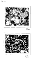
- Figs. 4A and 4B are photographs of the appearance of the granular resin-bonded magnet (I) with different magnifications. Apparent from these photographs, the microcapsules containing the liquid epoxy resin, the curing agent for the epoxy resin and calcium stearate are deposited in the fine particle form on the surfaces of the intermediate granules made of the Fe-B-R type magnet element and the solid epoxy resin having the Durran's softening temperature range of 65 to 75°C. Due to such structures, the granular resin-bonded magnet compound (I) is non-tacky at room temperature and has flowability suitable for compression molding.
- annular shape support member consisting of 22 sheets of doughnut shaped electromagnetic steel sheet each having an outer diameter of 47.9 mm, an inner diameter of 8 mm and a thickness of 0.5 mm and the granular resin-bonded magnet (I)
- the green compact was bonded around the support member in the same manner as above. Then, the article was removed from the mold and heated at 120°C for 1 hour. The green compact was firmly integrally bonded to the support member.
- a rotor shaft 15 was inserted to form a rotor member.
- the layer of the resin-bonded magnet having a wall thickness of about 1 mm was directly bonded to the peripheral surface of the support member having the outer diameter of 47.9 mm, the articles have very good dimensional accuracy.
- Fig. 6 is a graph showing the relationship between the shear strength between the support member and the resin-bonded magnet and the atmospheric temperature. As understood from this graph, the shear strength decreases at high temperatures due to the property of the binder resin. However, even at 100°C, the shear strength was still 300 kg, which means that the support member and the resin-bonded magnet were firmly integrally bonded.
- Fig. 7 is a photograph of the bonding surface of the resin-bonded magnet which was removed from the support member through shear fracture. This photograph shows that the microcapsules as the binder component were mechanically broken during the formation of the green compact from the granular resin-bonded magnet. The contents of the microcapsules, which was, in this Example, the glycidyl ether type epoxy resin having the viscosity of 100-160 poises at 25°C were discharged to wet the support member directly.
- annular shape support member consisting of 11 sheets of doughnut shaped electromagnetic steel sheet each having an outer diameter of 47.9 mm, an inner diameter of 8 mm and a thickness of 0.5 mm and the granular resin-bonded magnet (II)
- the green compact having the outer diameter of 50.2 mm was bonded around the support member in the same manner as above. Then, the article was removed from the mold and heated at 160°C for 1 hour. The green compact was firmly integrally bonded to the support member.
- the rotor shaft By inserting the rotor shaft in the bore of the support member, the rotor member was produced. The rotor member was rotated at 8,000 rpm for 6 hours in an atmosphere kept at 100°C. The resin-bonded magnet was not mechanically broken or removed from the support member by the centrifugal force.
- Example 5 In the same manner as in Example 5, around the annular shape support member consisting of 11 sheets of doughnut shaped electromagnetic steel sheet each having an outer diameter of 47.9 mm, an inner diameter of 8 mm and a thickness of 0.5 mm, the prepared raw material was molded in the cavity having the outer diameter of 50.2 mm. Not only it was difficult to charge the raw material in the cavity but also the resin-bonded magnet was cracked due to shrinkage caused by solidification of the melt resin.
- Fig. 8 shows a perspective view of a conventional rotor member comprising a support member 15 consisting of the laminated electromagnetic steel sheet each having a thickness of 0.5 mm, a sintered ferrite magnets 16 with 4.2 MGOe to which magnetic anisotropy is imparted in the wall thickness direction and a shaft 17 assembled in the support member.
- the ferrite magnets are bonded to the peripheral surface of the support member with an adhesive.
- the outer diameter of the rotor member is 50.2 mm, which is substantially the same as the diameter of the rotor member of Fig. 5 (Example 5).
- the thickness and the volume of the magnet of Fig. 8 are 1.5 times and 4 times those of Fig. 5, respectively.
- Table 4 shows performances of the rotor members of Figs. 5 and 8 when they are used in a brushless fan motor which is one of the typical permanent magnet motors.
- the resin-bonded magnet article according to the present invention can be used in the field in which the conventional annular magnetic is hardly applied.
Landscapes
- Engineering & Computer Science (AREA)
- Power Engineering (AREA)
- Manufacturing & Machinery (AREA)
- Chemical & Material Sciences (AREA)
- Chemical Kinetics & Catalysis (AREA)
- Mechanical Engineering (AREA)
- Crystallography & Structural Chemistry (AREA)
- Inorganic Chemistry (AREA)
- Hard Magnetic Materials (AREA)
- Manufacturing Cores, Coils, And Magnets (AREA)
Claims (3)
- Procédé pour produire un article à aimant lié par une résine comprenant les étapes de fourniture d'un composé granulaire comprenant un aimant de type Fe-B-R dans lequel R est au moins un élément choisi dans le groupe consistant en Nb et Pr et des microcapsules contenant chacune au moins un constituant d'une composition de résine polymérisable thermiquement en tant que constituant liant dans une cavité formée par un élément de support et un moule, de compression du composé granulaire dans la cavité et de rupture mécanique d'au moins une partie des microcapsules pour évacuer des capsules les constituants de ladite composition de résine pour former un comprimé vert qui est intégré avec l'élément de support et de durcissement de la résine polymérisable thermiquement pour produire l'article à aimant lié par une résine.
- Procédé selon la revendication 1, dans lequel le composé granulaire est préparé par formation de granules intermédiaires comprenant au moins un constituant liant autre que les microcapsules et l'aimant de type Fe-B-R et mélange des granules intermédiaires avec les microcapsules et des additifs facultatifs.
- Procédé selon la revendication 1 ou 2, dans lequel l'élément de support consiste en une tôle d'acier électromagnétique annulaire laminée et le comprimé vert est moulé d'une pièce autour de la surface sphérique de l'élément de support.
Applications Claiming Priority (9)
| Application Number | Priority Date | Filing Date | Title |
|---|---|---|---|
| JP63046203A JP2558791B2 (ja) | 1988-02-29 | 1988-02-29 | 樹脂磁石の製造方法 |
| JP46203/88 | 1988-02-29 | ||
| JP63046232A JP2568615B2 (ja) | 1988-02-29 | 1988-02-29 | 樹脂磁石構造体の製造方法 |
| JP63046202A JP2558790B2 (ja) | 1988-02-29 | 1988-02-29 | 樹脂磁石の製造方法 |
| JP46202/88 | 1988-02-29 | ||
| JP46232/88 | 1988-02-29 | ||
| JP63976/88 | 1988-03-17 | ||
| JP6397688A JP2615781B2 (ja) | 1988-03-17 | 1988-03-17 | 樹脂磁石構造体の製造方法 |
| EP89103336A EP0331055B1 (fr) | 1988-02-29 | 1989-02-25 | Procédé pour fabriquer un aimant lié à de la résine |
Related Parent Applications (1)
| Application Number | Title | Priority Date | Filing Date |
|---|---|---|---|
| EP89103336.7 Division | 1989-02-25 |
Publications (3)
| Publication Number | Publication Date |
|---|---|
| EP0540504A2 EP0540504A2 (fr) | 1993-05-05 |
| EP0540504A3 EP0540504A3 (en) | 1993-06-09 |
| EP0540504B1 true EP0540504B1 (fr) | 1995-05-31 |
Family
ID=27461839
Family Applications (3)
| Application Number | Title | Priority Date | Filing Date |
|---|---|---|---|
| EP93100980A Expired - Lifetime EP0540504B1 (fr) | 1988-02-29 | 1989-02-25 | Procédé pour fabriquer un article aimant lié à une resine |
| EP89103336A Expired - Lifetime EP0331055B1 (fr) | 1988-02-29 | 1989-02-25 | Procédé pour fabriquer un aimant lié à de la résine |
| EP93100979A Expired - Lifetime EP0540503B1 (fr) | 1988-02-29 | 1989-02-25 | Procédé pour la fabrication d' article comprenant un aimant à liant resineux |
Family Applications After (2)
| Application Number | Title | Priority Date | Filing Date |
|---|---|---|---|
| EP89103336A Expired - Lifetime EP0331055B1 (fr) | 1988-02-29 | 1989-02-25 | Procédé pour fabriquer un aimant lié à de la résine |
| EP93100979A Expired - Lifetime EP0540503B1 (fr) | 1988-02-29 | 1989-02-25 | Procédé pour la fabrication d' article comprenant un aimant à liant resineux |
Country Status (3)
| Country | Link |
|---|---|
| US (1) | US4981635A (fr) |
| EP (3) | EP0540504B1 (fr) |
| DE (3) | DE68922748T2 (fr) |
Families Citing this family (26)
| Publication number | Priority date | Publication date | Assignee | Title |
|---|---|---|---|---|
| US5223759A (en) * | 1987-12-24 | 1993-06-29 | Seiko Epson Corporation | DC brushless motor with solid rotor having permanent magnet |
| JPH03201508A (ja) * | 1989-12-28 | 1991-09-03 | Sankyo Seiki Mfg Co Ltd | 樹脂結合型磁石の製造方法 |
| US5213703A (en) * | 1990-02-09 | 1993-05-25 | Matsushita Electric Industrial Co., Ltd. | Anisotropic neodymium-iron-boron system plastic bonded magnet |
| JP2780422B2 (ja) * | 1990-03-07 | 1998-07-30 | 松下電器産業株式会社 | 樹脂磁石構造体の製造方法 |
| JP2819748B2 (ja) * | 1990-03-23 | 1998-11-05 | 大同特殊鋼株式会社 | 薄肉長尺リング状磁石成形体の成形方法 |
| US5300156A (en) * | 1990-07-24 | 1994-04-05 | Kanegafuchi Kagaku Kogyo Kabushiki Kaisha | Bonded rare earth magnet and a process for manufacturing the same |
| US5240627A (en) * | 1990-07-24 | 1993-08-31 | Kanegafuchi Kagaku Kogyo Kabushiki Kaisha | Bonded rare earth magnet and a process for manufacturing the same |
| IT1246925B (it) * | 1991-04-04 | 1994-11-29 | Ricerca Elettromeccanica Srl | Metodo per la produzione di parti di motori elettrici e motori utilizzanti parti prodotte con detto metodo |
| EP0507324A3 (en) * | 1991-04-05 | 1993-07-28 | Kanegafuchi Kagaku Kogyo Kabushiki Kaisha | Composite molding of resin-bonded magnet for machine parts and process for producing the same |
| US5624503A (en) * | 1992-12-24 | 1997-04-29 | Matsushita Electric Industrial Co., Ltd. | Process for producing Nd-Fe-B magnet |
| US5288447A (en) * | 1993-02-22 | 1994-02-22 | General Electric Company | Method of making permanent magnet rotors |
| SE9402497D0 (sv) * | 1994-07-18 | 1994-07-18 | Hoeganaes Ab | Iron powder components containing thermoplastic resin and methods of making same |
| RU2127923C1 (ru) * | 1997-01-27 | 1999-03-20 | Открытое акционерное общество Научно-производственное объединение "Магнетон" | Способ изготовления постоянных магнитов |
| US6365078B1 (en) | 1997-05-30 | 2002-04-02 | Matsushita Electric Industrial Co., Ltd. | Production process for ring shaped resin bonded magnet |
| DE19840914C2 (de) * | 1998-09-08 | 2000-09-07 | Baermann Max Gmbh | Kunststoffgebundener Ringmagnet |
| US6188304B1 (en) * | 2000-03-03 | 2001-02-13 | Delphi Technologies, Inc. | Ignition coil with microencapsulated magnets |
| US7850524B2 (en) * | 2003-03-25 | 2010-12-14 | Wms Gaming Inc. | Progressive jackpot game with special bonus |
| JP5267800B2 (ja) * | 2009-02-27 | 2013-08-21 | ミネベア株式会社 | 自己修復性希土類−鉄系磁石 |
| JP5976284B2 (ja) * | 2010-07-23 | 2016-08-23 | 株式会社豊田中央研究所 | 圧粉磁心の製造方法および磁心用粉末の製造方法 |
| DE102013213646A1 (de) * | 2013-07-12 | 2015-01-15 | Siemens Aktiengesellschaft | Anisotroper seltenerdfreier matrixgebundener hochperformanter Permanentmagnet mit nanokristalliner Struktur und Verfahren zu dessen Herstellung |
| US20150171717A1 (en) * | 2013-12-17 | 2015-06-18 | GM Global Technology Operations LLC | Net shaped aligned and sintered magnets by modified mim processing |
| EP3444927B1 (fr) * | 2016-04-13 | 2024-04-10 | Kuroda Precision Industries Ltd. | Procédé de fabrication d'un corps d'empliment de tôles comprenant des aimants incorporés |
| CN108305740B (zh) * | 2018-01-28 | 2020-03-31 | 孔金英 | 一种高穿透粘结磁体及其制备方法 |
| US12257770B2 (en) | 2019-10-10 | 2025-03-25 | Hewlett-Packard Development Company, L.P. | Three-dimensional printing with dihydrazides and glycidyl compounds |
| CN113410018B (zh) * | 2021-06-25 | 2022-11-18 | 深圳市铂科新材料股份有限公司 | 一种磁性复合材料三维结构、其加工方法和用途 |
| LU103319B1 (de) * | 2024-06-24 | 2025-12-24 | Wilo Se | Verfahren und Stoffgemsich zur Herstellung kunststoffgebundener Permanentmagnete aus recyceltem, pulverförmigem Magnetmaterial |
Family Cites Families (29)
| Publication number | Priority date | Publication date | Assignee | Title |
|---|---|---|---|---|
| DE970931C (de) * | 1943-08-21 | 1958-10-30 | Societe d'Electro-Chimie, d'Electro-Mctallurgie et des Acieries electriques d'Ugine, Paris | Verfahren zur Herstellung von Dauermagneten aus Eisen- und Kobaltoxyden |
| US3024392A (en) * | 1954-08-27 | 1962-03-06 | Baermann Max | Process for the manufacture of plastic bound permanent magnets |
| US3223668A (en) * | 1962-04-23 | 1965-12-14 | Owens Corning Fiberglass Corp | Phenol-aldehyde, dicyandiamide binder composition |
| US3281515A (en) * | 1963-01-31 | 1966-10-25 | Hodges Chemicals Company | Resin curing |
| US3246060A (en) * | 1963-04-01 | 1966-04-12 | Leyman Corp | Method of making machinable high energy permanent magnets |
| US3849213A (en) * | 1966-09-01 | 1974-11-19 | M Baermann | Method of producing a molded anisotropic permanent magnet |
| DE1944432C3 (de) * | 1969-09-02 | 1980-03-20 | Strnat, Karl, Prof. Dr., La Jolla, Calif. (V.St.A.) | Dauermagnet |
| GB1366541A (en) * | 1971-01-26 | 1974-09-11 | Lucas Industries Ltd | Method of manufacturing a ferrite magnet |
| US3974246A (en) * | 1972-05-26 | 1976-08-10 | Corning Glass Works | Method of improving the magnetic properties of cobalt substituted magnetite |
| JPS5426499A (en) * | 1977-07-29 | 1979-02-28 | Seiko Epson Corp | Permanent magnetic structure |
| JPS5563808A (en) * | 1978-11-07 | 1980-05-14 | Seiko Epson Corp | Manufacture of rare-earth metal intermetallic compound magnet |
| CH644655A5 (en) * | 1979-07-30 | 1984-08-15 | Micafil Ag | Process and apparatus for producing insulating webs |
| SU1007832A1 (ru) * | 1980-10-10 | 1983-03-30 | Харьковский Ордена Ленина Авиационный Институт Им.Н.Е.Жуковского | Способ получени магнитом гкого материала |
| US4324753A (en) * | 1980-11-03 | 1982-04-13 | Gill Robert A | Method of producing an air laid paper web utilizing microencapsulated hydrogen bond promoting material |
| EP0100055B1 (fr) * | 1982-07-22 | 1986-12-03 | Matsushita Electric Industrial Co., Ltd. | Matériau de friction |
| SU1103944A1 (ru) * | 1982-08-13 | 1984-07-23 | Ленинградский Ордена Октябрьской Революции И Ордена Трудового Красного Знамени Технологический Институт Им.Ленсовета | Способ обработки пресспорошков гексаферрита бари |
| US4851058A (en) * | 1982-09-03 | 1989-07-25 | General Motors Corporation | High energy product rare earth-iron magnet alloys |
| JPS59136908A (ja) * | 1983-01-27 | 1984-08-06 | Seiko Epson Corp | 永久磁石 |
| JPS59140335A (ja) * | 1983-01-29 | 1984-08-11 | Hitachi Metals Ltd | 希土類コバルト系異形焼結磁石の製造方法 |
| US4684406A (en) * | 1983-05-21 | 1987-08-04 | Sumitomo Special Metals Co., Ltd. | Permanent magnet materials |
| US4558077A (en) * | 1984-03-08 | 1985-12-10 | General Motors Corporation | Epoxy bonded rare earth-iron magnets |
| JPS60194509A (ja) * | 1984-03-16 | 1985-10-03 | Asahi Chem Ind Co Ltd | 樹脂結合型磁石の製造方法 |
| US4678634A (en) * | 1985-04-18 | 1987-07-07 | Shin-Etsu Chemical Co., Ltd. | Method for the preparation of an anisotropic sintered permanent magnet |
| JPS61272914A (ja) * | 1985-05-28 | 1986-12-03 | Seiko Epson Corp | 熱硬化性樹脂結合磁石の製造方法 |
| JPS6286809A (ja) * | 1985-10-14 | 1987-04-21 | Seiko Epson Corp | 円筒状異方性磁石の製造方法 |
| US4689163A (en) * | 1986-02-24 | 1987-08-25 | Matsushita Electric Industrial Co., Ltd. | Resin-bonded magnet comprising a specific type of ferromagnetic powder dispersed in a specific type of resin binder |
| JP2530641B2 (ja) * | 1986-03-20 | 1996-09-04 | 日立金属株式会社 | 磁気異方性ボンド磁石、それに用いる磁粉及びその製造方法 |
| DE3626360C2 (de) * | 1986-08-04 | 1995-06-22 | Vogt Electronic Ag | Herstellungsvefahren für zwei- und mehrpolige Dauermagnete mit hoher magnetischer Energiedichte |
| JPS6347301A (ja) * | 1986-08-15 | 1988-02-29 | Matsushita Electric Works Ltd | 永久磁石粉末の製法 |
-
1989
- 1989-02-25 EP EP93100980A patent/EP0540504B1/fr not_active Expired - Lifetime
- 1989-02-25 EP EP89103336A patent/EP0331055B1/fr not_active Expired - Lifetime
- 1989-02-25 DE DE68922748T patent/DE68922748T2/de not_active Expired - Lifetime
- 1989-02-25 DE DE68922911T patent/DE68922911T2/de not_active Expired - Lifetime
- 1989-02-25 EP EP93100979A patent/EP0540503B1/fr not_active Expired - Lifetime
- 1989-02-25 DE DE68912157T patent/DE68912157T2/de not_active Expired - Lifetime
- 1989-02-28 US US07/316,967 patent/US4981635A/en not_active Expired - Lifetime
Also Published As
| Publication number | Publication date |
|---|---|
| DE68922748T2 (de) | 1996-02-01 |
| US4981635A (en) | 1991-01-01 |
| DE68922911D1 (de) | 1995-07-06 |
| DE68922748D1 (de) | 1995-06-22 |
| EP0331055B1 (fr) | 1994-01-12 |
| DE68912157T2 (de) | 1994-06-16 |
| EP0540503A2 (fr) | 1993-05-05 |
| EP0540504A3 (en) | 1993-06-09 |
| EP0540503A3 (en) | 1993-06-09 |
| DE68912157D1 (de) | 1994-02-24 |
| EP0540504A2 (fr) | 1993-05-05 |
| EP0540503B1 (fr) | 1995-05-17 |
| DE68922911T2 (de) | 1996-02-08 |
| EP0331055A1 (fr) | 1989-09-06 |
Similar Documents
| Publication | Publication Date | Title |
|---|---|---|
| EP0540504B1 (fr) | Procédé pour fabriquer un article aimant lié à une resine | |
| US5464670A (en) | Resin bound magnet and its production process | |
| US8853908B2 (en) | Magnet rotor assembly including a vacuum impregnated bonded magnet having increased crush strength at high temperatures | |
| US5149477A (en) | Process for producing a resin bonded magnet structure | |
| US12142403B2 (en) | Anisotropic bonded magnet and preparation method thereof | |
| JP7477745B2 (ja) | 界磁子およびその製造方法 | |
| US6007757A (en) | Method of producing an anisotropic bonded magnet | |
| US5190684A (en) | Rare earth containing resin-bonded magnet and its production | |
| JP3675452B2 (ja) | ボンド磁石の製造方法 | |
| JP2568615B2 (ja) | 樹脂磁石構造体の製造方法 | |
| JP2615781B2 (ja) | 樹脂磁石構造体の製造方法 | |
| KR920002258B1 (ko) | 수지자석 및 수지자석구조체의 제조방법 | |
| JP3883138B2 (ja) | 樹脂ボンド磁石の製造方法 | |
| JP7623600B2 (ja) | 圧縮ボンド磁石の製造方法 | |
| JP2558790B2 (ja) | 樹脂磁石の製造方法 | |
| JP3024436B2 (ja) | 樹脂磁石構造体の製造方法 | |
| JP2021190707A (ja) | 異方性結合磁石およびその作製方法 | |
| JP7640843B2 (ja) | 圧縮ボンド磁石の製造方法 | |
| JP4075173B2 (ja) | 樹脂磁石コンパウンドの製造方法 | |
| EP4567843A1 (fr) | Préforme, procédé de préformage et procédé de production d'aimant lié par compression | |
| JP2839264B2 (ja) | 永久磁石 | |
| WO2024181326A1 (fr) | Procédé de fabrication d'un élément de champ | |
| JPH0444302A (ja) | 希土類鉄系樹脂磁石構造体の製造方法 | |
| WO2026047802A1 (fr) | Composé et aimant lié | |
| WO2026047800A1 (fr) | Composé et aimant lié |
Legal Events
| Date | Code | Title | Description |
|---|---|---|---|
| PUAI | Public reference made under article 153(3) epc to a published international application that has entered the european phase |
Free format text: ORIGINAL CODE: 0009012 |
|
| PUAL | Search report despatched |
Free format text: ORIGINAL CODE: 0009013 |
|
| 17P | Request for examination filed |
Effective date: 19930122 |
|
| AC | Divisional application: reference to earlier application |
Ref document number: 331055 Country of ref document: EP |
|
| AK | Designated contracting states |
Kind code of ref document: A2 Designated state(s): DE GB |
|
| AK | Designated contracting states |
Kind code of ref document: A3 Designated state(s): DE GB |
|
| 17Q | First examination report despatched |
Effective date: 19940304 |
|
| GRAA | (expected) grant |
Free format text: ORIGINAL CODE: 0009210 |
|
| AC | Divisional application: reference to earlier application |
Ref document number: 331055 Country of ref document: EP |
|
| AK | Designated contracting states |
Kind code of ref document: B1 Designated state(s): DE GB |
|
| REF | Corresponds to: |
Ref document number: 68922911 Country of ref document: DE Date of ref document: 19950706 |
|
| PLBE | No opposition filed within time limit |
Free format text: ORIGINAL CODE: 0009261 |
|
| STAA | Information on the status of an ep patent application or granted ep patent |
Free format text: STATUS: NO OPPOSITION FILED WITHIN TIME LIMIT |
|
| 26N | No opposition filed | ||
| REG | Reference to a national code |
Ref country code: GB Ref legal event code: IF02 |
|
| PGFP | Annual fee paid to national office [announced via postgrant information from national office to epo] |
Ref country code: GB Payment date: 20080220 Year of fee payment: 20 Ref country code: DE Payment date: 20080221 Year of fee payment: 20 |
|
| REG | Reference to a national code |
Ref country code: GB Ref legal event code: PE20 Expiry date: 20090224 |
|
| PG25 | Lapsed in a contracting state [announced via postgrant information from national office to epo] |
Ref country code: GB Free format text: LAPSE BECAUSE OF EXPIRATION OF PROTECTION Effective date: 20090224 |