EP0541506A2 - Brandschutzelement und Kastenkonstruktion - Google Patents
Brandschutzelement und Kastenkonstruktion Download PDFInfo
- Publication number
- EP0541506A2 EP0541506A2 EP92870186A EP92870186A EP0541506A2 EP 0541506 A2 EP0541506 A2 EP 0541506A2 EP 92870186 A EP92870186 A EP 92870186A EP 92870186 A EP92870186 A EP 92870186A EP 0541506 A2 EP0541506 A2 EP 0541506A2
- Authority
- EP
- European Patent Office
- Prior art keywords
- face
- extending
- box
- parts
- edge
- Prior art date
- Legal status (The legal status is an assumption and is not a legal conclusion. Google has not performed a legal analysis and makes no representation as to the accuracy of the status listed.)
- Withdrawn
Links
Images


Classifications
-
- C—CHEMISTRY; METALLURGY
- C04—CEMENTS; CONCRETE; ARTIFICIAL STONE; CERAMICS; REFRACTORIES
- C04B—LIME, MAGNESIA; SLAG; CEMENTS; COMPOSITIONS THEREOF, e.g. MORTARS, CONCRETE OR LIKE BUILDING MATERIALS; ARTIFICIAL STONE; CERAMICS; REFRACTORIES; TREATMENT OF NATURAL STONE
- C04B26/00—Compositions of mortars, concrete or artificial stone, containing only organic binders, e.g. polymer or resin concrete
- C04B26/02—Macromolecular compounds
- C04B26/10—Macromolecular compounds obtained otherwise than by reactions only involving carbon-to-carbon unsaturated bonds
-
- C—CHEMISTRY; METALLURGY
- C04—CEMENTS; CONCRETE; ARTIFICIAL STONE; CERAMICS; REFRACTORIES
- C04B—LIME, MAGNESIA; SLAG; CEMENTS; COMPOSITIONS THEREOF, e.g. MORTARS, CONCRETE OR LIKE BUILDING MATERIALS; ARTIFICIAL STONE; CERAMICS; REFRACTORIES; TREATMENT OF NATURAL STONE
- C04B26/00—Compositions of mortars, concrete or artificial stone, containing only organic binders, e.g. polymer or resin concrete
- C04B26/30—Compounds having one or more carbon-to-metal or carbon-to-silicon linkages ; Other silicon-containing organic compounds; Boron-organic compounds
- C04B26/32—Compounds having one or more carbon-to-metal or carbon-to-silicon linkages ; Other silicon-containing organic compounds; Boron-organic compounds containing silicon
-
- C—CHEMISTRY; METALLURGY
- C09—DYES; PAINTS; POLISHES; NATURAL RESINS; ADHESIVES; COMPOSITIONS NOT OTHERWISE PROVIDED FOR; APPLICATIONS OF MATERIALS NOT OTHERWISE PROVIDED FOR
- C09K—MATERIALS FOR MISCELLANEOUS APPLICATIONS, NOT PROVIDED FOR ELSEWHERE
- C09K21/00—Fireproofing materials
- C09K21/02—Inorganic materials
-
- E—FIXED CONSTRUCTIONS
- E04—BUILDING
- E04B—GENERAL BUILDING CONSTRUCTIONS; WALLS, e.g. PARTITIONS; ROOFS; FLOORS; CEILINGS; INSULATION OR OTHER PROTECTION OF BUILDINGS
- E04B1/00—Constructions in general; Structures which are not restricted either to walls, e.g. partitions, or floors or ceilings or roofs
- E04B1/62—Insulation or other protection; Elements or use of specified material therefor
- E04B1/92—Protection against other undesired influences or dangers
- E04B1/94—Protection against other undesired influences or dangers against fire
- E04B1/941—Building elements specially adapted therefor
- E04B1/942—Building elements specially adapted therefor slab-shaped
-
- E—FIXED CONSTRUCTIONS
- E04—BUILDING
- E04B—GENERAL BUILDING CONSTRUCTIONS; WALLS, e.g. PARTITIONS; ROOFS; FLOORS; CEILINGS; INSULATION OR OTHER PROTECTION OF BUILDINGS
- E04B1/00—Constructions in general; Structures which are not restricted either to walls, e.g. partitions, or floors or ceilings or roofs
- E04B1/62—Insulation or other protection; Elements or use of specified material therefor
- E04B1/92—Protection against other undesired influences or dangers
- E04B1/94—Protection against other undesired influences or dangers against fire
- E04B1/945—Load-supporting structures specially adapted therefor
Definitions
- the subject of the present invention is a protective element against hydrocarbon fire, in particular for producing removable protective casings against hydrocarbon fires with door (s) and vent (s) for a minimum duration, for example included between 60 and 120 minutes.
- fire protection boxes for example to protect valves, conduits, etc. from various industries, in particular chemical and petrochemical, have been produced according to another design.
- the present invention also aims to remedy this problem and relates to fire protection elements making it possible to produce fire-resistant boxes for which the problems sealing walls are resolved, that is to say for which the risk of channel formation is eliminated.
- the element for making a box or part of a fire protection box extends between a first face intended to form an internal face of the box and a second face opposite to said first face and intended to form an external face of the box and has a lateral face extending between said first and second faces, this lateral face having *, between an edge of the first face and an edge of the second face, a shape having at least two parts extending in different directions.
- the lateral face * has a curved shape
- the plane tangent to a part of the lateral face * is inclined relative to the plane tangent to another part of said lateral face *.
- each of the elements (side walls, support, cover) for producing a box extends between a first face intended to form an internal face of the box and a second face opposite to said first face and intended to form an external face of the box and has a lateral face extending between said first and second faces, this lateral face having, between an edge of the first face and an edge of the second face, a shape having at least two parts extending in different directions .
- the lateral face has, between an edge of the first face and an edge of the second face, at least two planar parts extending in orthogonal directions.
- the lateral face extending between a edge of the first face and an edge of the second face has a stepped shape comprising two plane parts parallel to each other and connected together by a plane part extending in a plane orthogonal to said two parallel parts.
- the planar part extending between said parallel parts has a length substantially equal to the height of one or more parallel parts.
- the element comprises a support, and either an anti-fire layer (by release of water, for example of bonding or by another principle) or either an anti-fire layer and an insulating layer.
- said first and second faces have a substantially square or rectangular shape and the element has four lateral faces each extending between an edge of the first face and an edge of the second face which is parallel to the edge of the first face.
- the present invention also relates to a protective box produced by means of elements according to the invention or comprising at least one element according to the invention, for example to form a door of the box.
- a protective box produced by means of elements according to the invention or comprising at least one element according to the invention, for example to form a door of the box.
- Such a box is useful for protecting parts or parts of pipes in chemical, petrochemical or petroleum installations.
- a box according to the invention produced by means of elements the lateral face of which extends between an edge of the first face and an edge of the second face has a stepped shape comprising two plane parts parallel to each other and connected to each other by a plane part extending in a plane orthogonal to said two parallel parts, and of which said first and second faces have a substantially square or rectangular shape so that the element has four lateral faces s 'each extending between an edge of the first face and an edge of the second face which is parallel to said edge of the first face, one of said parallel parts and the part extending between them of a lateral face of an element bear respectively on one of the parallel parts and on the part extending between them of a lateral face of an adjacent element or on the part extending between parallel parts and on one of the parallel parts of a face side of an adjacent element.
- a box has an opening extending in an element of the box, said opening being defined by a face or faces extending between a first face of the element intended to form a internal face of the box and a second face of the element intended to form an external face of the box. Between an edge of the opening on the first face and an edge of the opening on the second face of the element, the face or faces of the opening extending between said first and second faces have a shape having at least two parts which extend in different directions, preferably orthogonal. The passage area from the opening to the second face of the wall is greater than that of the opening from the side of the first face.
- the face or faces which define the opening present between said first and second faces two preferably planar parts, extending in orthogonal directions, preferably orthogonal planes.
- the face extending between an edge of the opening on the second face of the element and an edge of the opening on the first face of the element has a stepped shape comprising two plane parts parallel to each other. and connected together by a planar part extending in a plane orthogonal to said two parallel parts.
- the door intended to close the opening of the box is advantageously an element according to the invention, the face or the lateral faces of which conform to the shape of the face or faces defining the opening.
- the fire protection boxes are advantageously provided with a drain and a vent.
- a vent which is particularly suitable for protective boxes according to the invention consists for example of a conduit provided with a series of plates containing an intumescent material, each plate partially closing off the passage surface of the conduit, said plates being placed one above the other so as to form a passage in the duct between the end plates.
- the plates When said duct has a circular cross section, the plates have a circular shape from which at least a part, segment or sector has been removed so as to form a channel between the opposite faces of the plate, the plates being placed one above the other. another so that the channel of a platelet communicates with the channel of adjacent platelets.
- the elements of a box according to the invention are interconnected by means allowing partial disassembly, preferably total, of the box.
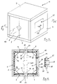
- FIG. 1 represents a box according to the invention intended to protect a valve against fire.
- This box comprises a series of elements placed in relation to each other, so that a side wall of an element touches a surface of an adjacent element.
- the box 1 comprises a lower element 2 resting on a foot not shown, an element 3 and side elements 4,5,6,7,8 and 9.
- the side elements 6,7,8,9 are connected in pairs to form two partitions opposite one another. These elements have in the vicinity of one of their edges 61,71,81,91 a recessed part 62,72,82,92.
- the parties in withdrawal 62.72; 82.92 of two adjacent elements 6.7; 8, 9 form a passage in said partitions for the conduit 10 on which the valve 101 to be protected is mounted.
- the elements extend between a first face 11 intended to form an internal face of the box and a second face 12 intended to form an external face of the box (see FIG. 4). These elements have lateral faces 13a, 13b, 13c, 13d which extend between said first and second faces 11,12. These lateral faces have, between an edge 14 of the first face 11 and an edge 15 of the second face 12, a shape having at least two parts 18, 20 extending in different directions.
- the lateral faces 13a, 13b, 13c, 13d extend between the flat faces 11,12 which are parallel to each other and have three flat parts, namely a first part 18 adjacent to the internal face 11, a second part 19 adjacent to the external face 12 and a third part 20 extending between said first and second parts in a plane orthogonal to these said first and second parts.
- the first and second parts 18, 19 extend in a plane orthogonal to the planes in which the internal and external faces 11, 12 extend and therefore the edges thereof.
- the side faces therefore have a staircase shape.
- the height h of the steps, that is to say of the parts 18, 19 is advantageously substantially equal to the width 1 of the part 20 which extends between the parts 18,19. This allows a correct fitting of a lateral face of a element with a side face of an adjacent element.
- the various elements include a support 21, a fire-resistant layer 22 such as, for example, a layer of concrete or epoxy resin and an insulating layer 23, such as, for example, a layer of resin, polyurethane. , layer based on rock wool, etc.
- a fire-resistant layer 22 such as, for example, a layer of concrete or epoxy resin
- an insulating layer 23 such as, for example, a layer of resin, polyurethane. , layer based on rock wool, etc.
- the supports of the elements have tabs 24, a rod 25 extending between two tabs of two supports of adjacent elements so as to join them.
- the support 21 is provided on the face opposite to that carrying the tabs 24 with an insulating layer 23, a layer which extends beyond the support 21 so that part of the layer 23 overhangs the support 21, for example over a distance greater than h over the entire periphery of the support. This possibly prevents the support of an element from touching the fire-resistant layer, for example concrete 22 of an adjacent element.
- This insulating layer covers the face of the fire-resistant layer 22 which faces the support 21.
- the layer 22 is for example made of a porous concrete containing a binder and a filler capable of releasing binding water, such as Al (OH) 3, or is a layer of resin, for example epoxy, loaded with various materials.
- concrete contains from 10 to 60% of filler based on Al (OH) 3 and fibrous materials and from 10 to 30% by volume of polymeric binder, the rest being made up of cement, sand, etc.
- Two adjacent elements have interlocking side faces.
- the lateral face 13a of element 5 touches the lateral face 13d of element 6 so that part 20 and part 19 of the lateral face 13a of element 5 rest on part 18 and part 20 of the lateral face 13d of element 6 (see Figure 4).
- the elements 5,6,7,4,8,9 thus form a conduit having on its lower part and on its upper part a recessed part intended to serve as a support for parts of the lateral face of the elements 2 and 3.
- the upper element 3 can simply be placed on the frame or recessed part formed by the elements 4,5,6,7,8 and 9 so as to be able to serve as a door for the box for the maintenance of the valve, one (4) of the elements is advantageously provided with an opening 26 which can be closed by a door 27.
- Said opening 26 is pierced in the element 4 and therefore extends between the internal face 11 and the external face 12 of the element 4.
- This opening is defined by four lateral faces 28. These faces 28 which extend between a edge 29 of the opening 26 to the second face 12 (external) and an edge 30 of the opening 26 to the first face 11 (internal) have a shape having at least two parts 31, 32 extending in orthogonal directions (orthogonal plans).
- the passage surface of the opening 26 to the external face 12 is greater than that of the opening 26 to the internal face.
- the faces 28 comprise three parts, namely a part 31 adjacent to the internal face 11 and extending in a plane perpendicular to this face 11, a part 33 adjacent to the external face 12 and extending in a plane perpendicular to this face 12, and a part 32 extending between said parts 31, 33 and in a plane parallel to the internal face 11 or external face 12.
- the door 27 is an element according to the invention, the lateral faces 34 which extend between the face 35 intended to be turned towards the outside of the box and the face 36 intended to be turned towards the inside of the box have a shape intended to match the shapes of the faces 28 defining the opening 26.
- This door is advantageously provided with a handle 27.
- This handle is for example obtained by welding the free ends of a U-shaped part on the support 21 of the door.
- the box or housing is advantageously provided with a drain and a vent.
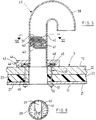
- a vent for a fire-resistant box is shown on a larger scale in FIG. 5.
- This vent 37 comprises a duct 38 whose end is bent.
- This conduit is provided with a series of plates 39, 40, 41 containing an intumescent material.
- the duct 38 has in cross section a circular passage section.
- the plates 39, 40, 41 have a circular shape corresponding to the passage section of the conduit 38 but from which a segment or part 41 has been removed. Each plate 39, 40, 41 therefore partially blocks the passage section of the conduit 38.
- the plates 39, 40, 41 are placed one above the other so that the channel formed by a plate and the internal wall of the conduit 38 communicates with the channel of adjacent plates.
- a substantially helical channel 42 is formed between the end plates.
- the conduit 38 is integral with a support block 43 consisting of a plate 44 on which the conduit 38 is fixed, for example by welding, an insulating layer 45 covering the plate 44, and a fire-resistant layer 46 covering the face of the insulating layer 45 opposite that adjacent to the plate 44 as well as the lateral faces of the insulating layer 45 and of the plate 44.
- the fixing of the support block 43 on the element 3 is obtained by bolts 47 whose head 48 is supported on the plate 44 and whose rod 49 is engaged in a hole in the plate 44 and in a channel which s extends between the outer face 12 and the inner face 11 of the element 3.
- the end 50 of the rod 49 is threaded and extends out of the channel formed in the element 3, so that by means of a nut 51 screwed onto said end, it is possible to tighten the support block 43 against the element 3.
Landscapes
- Chemical & Material Sciences (AREA)
- Engineering & Computer Science (AREA)
- Structural Engineering (AREA)
- Architecture (AREA)
- Ceramic Engineering (AREA)
- Organic Chemistry (AREA)
- Materials Engineering (AREA)
- Physics & Mathematics (AREA)
- Electromagnetism (AREA)
- Civil Engineering (AREA)
- Chemical Kinetics & Catalysis (AREA)
- Inorganic Chemistry (AREA)
- Special Wing (AREA)
- Building Environments (AREA)
Applications Claiming Priority (2)
| Application Number | Priority Date | Filing Date | Title |
|---|---|---|---|
| BE9101023A BE1005488A5 (fr) | 1991-11-06 | 1991-11-06 | Barriere et boitier antifeu. |
| BE9101023 | 1991-11-06 |
Publications (2)
| Publication Number | Publication Date |
|---|---|
| EP0541506A2 true EP0541506A2 (de) | 1993-05-12 |
| EP0541506A3 EP0541506A3 (en) | 1993-12-22 |
Family
ID=3885796
Family Applications (1)
| Application Number | Title | Priority Date | Filing Date |
|---|---|---|---|
| EP19920870186 Withdrawn EP0541506A3 (en) | 1991-11-06 | 1992-11-06 | Element and box used for fire protection |
Country Status (2)
| Country | Link |
|---|---|
| EP (1) | EP0541506A3 (de) |
| BE (1) | BE1005488A5 (de) |
Cited By (4)
| Publication number | Priority date | Publication date | Assignee | Title |
|---|---|---|---|---|
| FR2721680A1 (fr) * | 1994-06-28 | 1995-12-29 | Udd Fim | Caisson de protection thermique d'un équipement. |
| WO2000029685A1 (de) * | 1998-11-17 | 2000-05-25 | Otto Lampertz Gmbh & Co. Kg | Sicherheitsraum für informationstechnische einrichtungen |
| EP1964592A1 (de) * | 2007-02-27 | 2008-09-03 | IZEG Informationszentrum Entwässerungstechnik Guss e.V. | Vorrichtung zur Durchführung eines Kunststoffrohres durch eine Decke |
| WO2025151173A1 (en) * | 2024-01-12 | 2025-07-17 | Thermal Designs, Inc. | Improved fire retardant enclosure |
Family Cites Families (9)
| Publication number | Priority date | Publication date | Assignee | Title |
|---|---|---|---|---|
| US4413683A (en) * | 1980-10-20 | 1983-11-08 | Thermal Designs, Inc. | Fireproof enclosure for valve actuator |
| GB2110987B (en) * | 1981-10-06 | 1985-08-14 | Scott Bader Co | Laminates containing inorganic structural materials |
| DE3227500A1 (de) * | 1982-07-23 | 1984-01-26 | Monheimius, Manfred, 5657 Haan | Transportabler einbaukanal mit feuerschutz-klassifikation |
| GB2149300A (en) * | 1983-11-10 | 1985-06-12 | Insulation & Perlite Services | A heatshield housing and a method of assembling and making a heatshield housing |
| WO1985002430A1 (fr) * | 1983-12-02 | 1985-06-06 | Shikoku Kaken Kogyo Kabushiki Kaisha | Procede d'application de revetements ignifuges sur une structure en acier |
| DE3826183A1 (de) * | 1988-08-02 | 1990-02-08 | Britz Bernhard | Flammwidriger bis nichtbrennbarer kunststoffmodifizierter dispersionsputz und flammwidriges modifiziertes waermedaemmsystem aus dispersionsputz-, kleber- und fueller mit flexiblem armierungsgewebe auf polystrol-und/oder anderen waermedaemmplatten, fuer innen- und aussenanwendung |
| DE8914770U1 (de) * | 1989-12-15 | 1990-02-08 | Herberts Gmbh, 5600 Wuppertal | Brandschutzvorrichtung für temperaturempfindliche Einrichtungen, insbesondere Gasleitungen aus Blei und Kabelführungen |
| DE4119390C2 (de) * | 1991-06-12 | 1995-09-14 | Johne Patricia Vertreten Durch | Verfahren zum Aufbereiten und auslaugbeständigen Verfestigen von Filterstäuben und Reaktionsprodukten aus der Rauchgasreinigung von Abfall- und Klärschlammverbrennungsanlagen |
| FI99217C (fi) * | 1995-07-03 | 1997-10-27 | Nokia Telecommunications Oy | Menetelmä tukiaseman summausverkon virittämiseksi, kytkentäelin sekä kaistanpäästösuodatin |
-
1991
- 1991-11-06 BE BE9101023A patent/BE1005488A5/fr not_active IP Right Cessation
-
1992
- 1992-11-06 EP EP19920870186 patent/EP0541506A3/fr not_active Withdrawn
Cited By (5)
| Publication number | Priority date | Publication date | Assignee | Title |
|---|---|---|---|---|
| FR2721680A1 (fr) * | 1994-06-28 | 1995-12-29 | Udd Fim | Caisson de protection thermique d'un équipement. |
| WO2000029685A1 (de) * | 1998-11-17 | 2000-05-25 | Otto Lampertz Gmbh & Co. Kg | Sicherheitsraum für informationstechnische einrichtungen |
| US6789363B1 (en) | 1998-11-17 | 2004-09-14 | Otto Lampertz Gmbh & Co. Kg | Security room for information technology facilities |
| EP1964592A1 (de) * | 2007-02-27 | 2008-09-03 | IZEG Informationszentrum Entwässerungstechnik Guss e.V. | Vorrichtung zur Durchführung eines Kunststoffrohres durch eine Decke |
| WO2025151173A1 (en) * | 2024-01-12 | 2025-07-17 | Thermal Designs, Inc. | Improved fire retardant enclosure |
Also Published As
| Publication number | Publication date |
|---|---|
| EP0541506A3 (en) | 1993-12-22 |
| BE1005488A5 (fr) | 1993-08-10 |
Similar Documents
| Publication | Publication Date | Title |
|---|---|---|
| FR2507594A1 (fr) | Ensemble modulaire en fibres ceramiques pour le garnissage des fours et son mode de mise en oeuvre | |
| EP0856117B1 (de) | Modulare manschette zum schutz zur reparatur oder zur auskleidung einer rohrleitung | |
| EP0541506A2 (de) | Brandschutzelement und Kastenkonstruktion | |
| EP0087350A1 (de) | Einrichtung zum Neutronenschutz für ein radioaktives Produkt | |
| WO2012010773A1 (fr) | Bloc de coffrage isolant | |
| FR2813624A1 (fr) | Profile de raccord et d'etancheite, dispositif de raccord, panneau a structure sandwich, et ensemble de facade, de cloison ou de couverture | |
| FR3101936A1 (fr) | Equipement pour raccorder à l’air extérieur au moins un appareil thermodynamique à air | |
| EP0593362B1 (de) | Profileinrichtung für die Verkabelung elektrischer Apparate, und geeignetes Skelett und Rinne um eine solche Einrichtung zu bauen | |
| FR2719699A3 (fr) | Encastrement intérieur de container pour le transport et le stockage de combustible nucléaire. | |
| FR2742181A1 (fr) | Reservoir a mortier pour joints d'elements de construction prefabriques utilises en maconnerie | |
| FR2771224A1 (fr) | Procede de montage d'une boite d'encastrement dans une cloison creuse et boitier pour la mise en oeuvre d'un tel procede | |
| EP1001213A1 (de) | Schutzschalen gegen Korrosion und/oder Abrieb von einer Röhrenplatte und Verfahren zur Befestigung | |
| BE1003206A7 (fr) | Procede pour fermer un canal de gaz dans un systeme de refroidissement de coke a sec et dispositif pour la mise en oeuvre du procede. | |
| EP0210899B1 (de) | Entfernbare Abdeckplatte für eine Öffnung, die nur über einen engen Zugang zugänglich ist | |
| EP1452648B1 (de) | Wasserdichte Verschlussvorrichtung für eine Öffnung, insbesondere eine Schachtabdeckung | |
| EP1566591B1 (de) | Heizkessel mit Flammeumkehrung | |
| FR2895425A1 (fr) | Equipement de voirie coupe-feu. | |
| EP1983242A1 (de) | Vorrichtung zur Aufrechterhaltung der Entlüftungsleitungen von Gehäusen von Armaturenelementen vom Ventiltyp | |
| EP2805332B1 (de) | Sicherheitsventil und strahlungsschutzvorrichtung | |
| FR2920522A1 (fr) | Dispositif pour auto verrouiller les elements d'un poele a accumulation. | |
| EP1571273A1 (de) | Fussleiste zur Schützung eines Mauers oder einer Wand und Verfahren zum Herstellen dieser Leiste | |
| FR2957375A1 (fr) | Abri de piscine compose de plusieurs modules | |
| FR2558204A1 (fr) | Panneau de construction pour la protection de locaux bancaires ou analogues | |
| EP0924352B1 (de) | Inspektionskammer für unterirdisches Leitungssystem | |
| EP0967338B1 (de) | Spülkasten und sein Wasserzulauf |
Legal Events
| Date | Code | Title | Description |
|---|---|---|---|
| PUAI | Public reference made under article 153(3) epc to a published international application that has entered the european phase |
Free format text: ORIGINAL CODE: 0009012 |
|
| AK | Designated contracting states |
Kind code of ref document: A2 Designated state(s): AT BE CH DE DK ES FR GB GR IE IT LI LU MC NL PT SE |
|
| PUAL | Search report despatched |
Free format text: ORIGINAL CODE: 0009013 |
|
| AK | Designated contracting states |
Kind code of ref document: A3 Designated state(s): AT BE CH DE DK ES FR GB GR IE IT LI LU MC NL PT SE |
|
| 18D | Application deemed to be withdrawn |
Effective date: 19950127 |