EP2805332B1 - Sicherheitsventil und strahlungsschutzvorrichtung - Google Patents
Sicherheitsventil und strahlungsschutzvorrichtung Download PDFInfo
- Publication number
- EP2805332B1 EP2805332B1 EP12706876.5A EP12706876A EP2805332B1 EP 2805332 B1 EP2805332 B1 EP 2805332B1 EP 12706876 A EP12706876 A EP 12706876A EP 2805332 B1 EP2805332 B1 EP 2805332B1
- Authority
- EP
- European Patent Office
- Prior art keywords
- face
- shield
- opening
- radiation
- cavity
- Prior art date
- Legal status (The legal status is an assumption and is not a legal conclusion. Google has not performed a legal analysis and makes no representation as to the accuracy of the status listed.)
- Not-in-force
Links
- 230000003471 anti-radiation Effects 0.000 title claims description 16
- 239000012530 fluid Substances 0.000 claims description 27
- 239000000463 material Substances 0.000 claims description 23
- 230000005855 radiation Effects 0.000 claims description 22
- 239000012528 membrane Substances 0.000 claims description 9
- 238000000638 solvent extraction Methods 0.000 claims description 6
- 230000000694 effects Effects 0.000 claims description 4
- 238000005192 partition Methods 0.000 claims description 2
- 230000001902 propagating effect Effects 0.000 claims description 2
- 230000001681 protective effect Effects 0.000 claims 2
- 229910000831 Steel Inorganic materials 0.000 description 2
- 239000007788 liquid Substances 0.000 description 2
- 239000010959 steel Substances 0.000 description 2
- 230000004888 barrier function Effects 0.000 description 1
- 239000000567 combustion gas Substances 0.000 description 1
- 230000000295 complement effect Effects 0.000 description 1
- 230000006378 damage Effects 0.000 description 1
- 239000011810 insulating material Substances 0.000 description 1
- 239000011133 lead Substances 0.000 description 1
- 230000004048 modification Effects 0.000 description 1
- 238000012986 modification Methods 0.000 description 1
- 239000012188 paraffin wax Substances 0.000 description 1
- 238000003466 welding Methods 0.000 description 1
Images

Classifications
-
- G—PHYSICS
- G21—NUCLEAR PHYSICS; NUCLEAR ENGINEERING
- G21F—PROTECTION AGAINST X-RADIATION, GAMMA RADIATION, CORPUSCULAR RADIATION OR PARTICLE BOMBARDMENT; TREATING RADIOACTIVELY CONTAMINATED MATERIAL; DECONTAMINATION ARRANGEMENTS THEREFOR
- G21F7/00—Shielded cells or rooms
- G21F7/005—Shielded passages through walls; Locks; Transferring devices between rooms
-
- G—PHYSICS
- G21—NUCLEAR PHYSICS; NUCLEAR ENGINEERING
- G21F—PROTECTION AGAINST X-RADIATION, GAMMA RADIATION, CORPUSCULAR RADIATION OR PARTICLE BOMBARDMENT; TREATING RADIOACTIVELY CONTAMINATED MATERIAL; DECONTAMINATION ARRANGEMENTS THEREFOR
- G21F7/00—Shielded cells or rooms
- G21F7/005—Shielded passages through walls; Locks; Transferring devices between rooms
- G21F7/01—Transferring by fluidic means
Definitions
- the present invention relates to the field of valves or safety valves intended to be implemented in a partitioning element or closing and anti-radiation opening of the partition, wall or door leaf, anti-radiation and has the purpose a safety valve and anti-radiation device.
- a partitioning or closing and opening element hereinafter referred to as an element, comprises two opposite faces each extending, in the closed and / or partitioning state of said element, in one of the spaces situated one side or the other of the latter.
- Such an element can also be designed to fight against fires or be sealed to a fluid, liquid or gaseous.
- Such a safety valve is designed to be closed in the rest position and to be opened exceptionally when the pressure of the fluid under pressure in one of the spaces is greater than the calibration pressure of the valve, which has the effect of opening the passage cavity and pass said fluid through it and the element for its evacuation in the other space. It is equipped for this purpose with a shutter, such as for example a valve or a tear-off membrane respectively capable of being moved or torn under the effect of the overpressure of the fluid.
- WO 00/40880 A1 discloses a safety valve for a combustion gas chamber comprising a frame comprising a base plate and an intermediate clevis parallel to the plate and fixed thereto by means of four lower legs.
- the valve also includes a shutter slidably mounted and closing an opening through the plate.
- the intermediate clevis is formed by four beams radial support on the feet and has the function of preventing any ejection of the shutter beyond the cage.
- the shutter comprises a steel upper support and a lower layer of high temperature insulating material attached to the lower face of the latter.
- an anti-radiation element has a structure thickness of anti-radiation protection material, comprising one or more radiation protection material (s), for example steel, lead or paraffin, extending between the two opposite faces of the element.
- the structure of the radiation shielding material has the effect of allowing the element, in the closed and / or partitioning state, to stop or block the radiation propagating towards the latter, preventing them from cross and pass from one space to another.
- the thickness of the material structure is either substantially equal to the thickness of the element, or less than the latter.
- an anti-radiation element comprises a fluidic passage cavity closed by a safety valve
- said cavity also passes through the thickness of the radiation protection material structure.
- the length of radiation protection material structure cut by said axis is equal to the thickness of said structure, whereas in the case of a propagation axis inclined relative to said normal, the length of radiation protection material structure cut by said axis is greater than the thickness of said structure.
- the axis of propagation can, according to its angle of inclination and its point of entry into said cavity cut a length of radiation protection material structure less than the thickness of said structure and therefore a quantity of insufficient protection material to stop or block the corresponding radiation which then passes through the cavity and the element with possibly a greater or lesser attenuation.
- the present invention aims to overcome these disadvantages.
- the present invention relates to a safety valve and radiation protection device according to claim 1.
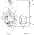
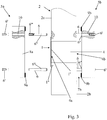
- the figures show a safety valve and radiation protection device comprising a safety valve 1 and an element 2 for partitioning or closing and anti-radiation opening, said element 2 comprising two opposite faces 2a and 2b, with namely a first face 2a and a second face 2b, a main material structure 3 of anti-radiation protection extending between said opposite faces and a cavity 4 of fluid passage closed by said valve 1 in the rest position, said cavity 4 passing through said element 2 and said structure 3 opening on the first face 2a by a first opening 4a and on the second face 1b by a second opening 4b so as to allow the evacuation of a fluid, not shown, overpressure through said cavity 4 during the exceptional opening of said valve 1.
- such a device further comprises one or two shield (s) 5a and / or 5b each comprising an additional material structure or complementary 3 'or 3 "of radiation protection and the shield or shields (s) ) 5a and / or 5b is (are) adapted to be fixed (s), by means of fastening means 6, respectively, on the first and / or second face 2a and / or 2b by covering a portion of the latter and covering the first and / or second opening 4a and / or 4b corresponding while leaving a gap 7a and / or 7b forming a fluid passage space between the or each shield and the first and / or second face 2a and / or 2b correspondingly, so, firstly, to stop or block any radiation likely to pass through the cavity 4 and / or the element 1 and, secondly, to allow the passage of fluid under pressure by the interstice 7a or 7b concerned for its evacuation through said cavity and said el ement.
- each shield 5a or 5b may comprise at least one cover face 8a or 8b, preferably flat, substantially flat or curved, capable of covering, in the attachment state of the latter or the latter, the part of the first or second face 2a or 2b including the first or the second opening 4a or 4b.
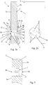
- each shield 5a or 5b may have a generally cylindrical right shape ( Figures 2a and 2b ) or right prismatic ( Figures 1a and 1b ) comprising two opposite base faces, for example two square base faces ( Figures 1a, 1b ), round ( Figures 2a and 2b ), rectangular or triangular.
- the height or thickness of the or each shield 5a or 5b may then be the distance separating said opposite base faces.
- one of said base faces may advantageously form the covering face 8a or 8b.
- the generally cylindrical shape will also be understood to be a form of disk or cylinder section ( Figures 2a and 2b ).
- the present invention can provide that the gap 7a or 7b is determined so that the lateral surface S ( figure 1a ) surrounding the portion of said gap 7a or 7b located in the axial extension of the fluid flow cavity 4, being greater than or equal to the area of the corresponding first or second opening 4a or 4b of said cavity. It will be understood that such a portion of the gap forms a reference gap that can be confused with the gap 7a or 7b in the case where the covering surface of the shield 5a or 5b, capable of covering the first or second opening 4a or 4b, is substantially identical to the surface of the latter.
- This reference gap then makes it possible to define the gap 7a or 7b to be respected between the shield 5a or 5b and the corresponding first or second face 2a or 2b to guarantee an efficient fluid passage between the shield 5a or 5b and the first or second face 2a or 2b, to the cavity 4 of fluid passage for evacuation of the fluid.
- Effective fluid passage will be understood to mean a fluidic passage making it possible, in spite of the presence of the shield (s) 5a and / or 5b, to evacuate the fluid from one space to another through the substantially identical fluidic passage cavity 4 or close to an evacuation obtained without the presence of said shields.
- the main material 3 and additional 3 'or 3 "structures may comprise one or more radiation protection material (s) may be, with respect to the nature of the materials (x) from which they are made, identical or different from each other.
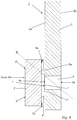
- the thickness and the surface extension of the or each shield 5a or 5b can be determined according to the present invention. invention so that any axis of propagation X ( figure 4 ) a radiation capable of passing through the cavity 4 and the element 1, whatever the angle of incidence of said axis, intersects a length of the main material structure 3 and / or additional 3 'and / or 3 "greater than or equal to the thickness of said main structure 3.
- the main material structures 3 and / or additional (s) 3 'and / or 3" are identical with respect to the nature of the or materials (x) from which they are made.
- an intumescent firearm seal 9a or 9b for example of annular shape, can be attached to the cover face 8a or 8b of the or at least one of said shield (s) 5a and / or 5b or on the first or second face 2a or 2b around the corresponding first or second opening 4a or 4b so as to be able to expand ( figure 6 ) in case of fire between the shield 5a or 5b concerned and the corresponding first or second face 2a or 2b by closing the fluid passage in the corresponding gap 7a or 7b and preferably in the aforementioned reference gap.
- the safety valve 1 may comprise a shutter in the form of a tear-off membrane ( Figures 1, 1a , 2, 2a , 3 , 4 and 6 ) and or flapper ( figure 5 ).
- a shutter 1 'of the membrane type said valve may be fixed on one of the opposite faces 2a or 2b of the element 2 by closing the corresponding first or second opening 4a or 4b.
- the safety valve 1 can be fixed on the side of the latter opposite its cover face 8a or 8b.
- such a shutter of the membrane type will preferably be positioned on the overpressure side, that is to say on the first or second face 2a or 2b located in the space containing a fluid likely to be in overpressure or to reach a maximum pressure greater than the calibration pressure of the valve, so that the membrane can open completely in the cavity 4 of fluid passage.
- the fixing of the membrane-type safety valve can be fixed on the first or second face 2a or 2b for example by means of screws 1 ".
- the fastening means of the or each shield 5a or 5b may consist of a plurality of connecting pins 6 spaced apart from each other and capable of ensuring, on the one hand, the rigid attachment or connection of said shield, more particularly of its covering face 8a or 8b, with the first or second face 2a or 2b of the element 2, this around the first or second opening 4a or 4b, and, secondly, the spacing between said shield and the first or second face 2a or 2b to form, preferably from the reference gap, the gap 7a or 7b.
- Each connecting pin 6 can be fixed by one of its free ends to the first or second face 2a or 2b, for example by welding or screwing, and by its other free end in the shield 5a or 5b, more particularly in its covering face 8a or 8b and crossing all or part of its thickness.
- the or each shield 5a or 5b may comprise a plurality of bores 10 made axially, preferably co-axially, in its overlapping face 8a or 8b, over all or part of its thickness, and the or each piercing 10 may be adapted to receive one of the free ends of one of said connecting pins 6 with holding and locking in said bore 10, for example by means of a screw 6 'screwed into a hole 6 "', threaded or not, practiced axially in said free end.
- the or each piercing 10 can be made in the overlap face 8a or 8b by passing right through the corresponding thickness of the shield 5a or 5b and opening on the face opposite to said cover face.
- Each screw 6 'making it possible to hold and lock the free end of the corresponding connecting pin 6 in the bore 10 in question can then be introduced into the opening opening on said face opposite to the covering face 8a or 8b.
- each axis 6 may comprise a shoulder 6 "forming an abutment coming against the covering face 8a or 8b so as to keep the shield 5a or 5b concerned away from the corresponding first or second face 2a or 2b in order to form, preferably from the reference gap, the gap 7a or 7b.
Landscapes
- Physics & Mathematics (AREA)
- Engineering & Computer Science (AREA)
- General Engineering & Computer Science (AREA)
- High Energy & Nuclear Physics (AREA)
- Safety Valves (AREA)
- Infusion, Injection, And Reservoir Apparatuses (AREA)
Claims (11)
- Sicherheitsventil- und Strahlungsschutzvorrichtung gebildet aus einem Ventil (1) und aus einem strahlungsabschirmenden Element (2) als Abtrennung oder zum Schließen und Öffnen vom Typ strahlungsabschirmende Trennwand, Wand oder Türblatt, wobei dieses Element (2) zwei sich gegenüberliegende Flächen (2a) und (2b) aufweist, nämlich eine erste Fläche (2a) und eine zweite Fläche (2b), die sich in einem geschlossenen und/oder abtrennenden Zustand des Elements (2) jeweils in einen der Räume auf der einen oder der anderen Seite des letzteren erstrecken, eine Hauptstruktur aus Material (3) zum Schutz gegen Strahlung, welche Struktur über ihre Dicke einen oder mehrere Strahlungsschutz-Werkstoff(e) aufweist, der oder die sich zwischen den sich gegenüberliegende Flächen und einem Hohlraum (4) zum Durchlassen von Fluid erstreckt oder erstrecken, welcher Hohlraum (4) durch das Ventil (1) in einer Ruhestellung geschlossen ist, welche Struktur die Funktion hat, es dem Element (2) in dem geschlossenen und/oder abtrennenden Zustand zu ermöglichen, Strahlung, beispielsweise vom Typ α, die sich auf letzteres zu bewegt, zu stoppen oder zu blockieren, indem es die Strahlung daran hindert, es zu durchqueren und vom einen Raum in den anderen zu gelangen, wobei der Hohlraum (4) das Element (2) und die Struktur (3) durchdringt und auf der ersten Fläche (2a) mittels einer ersten Öffnung (4a) sowie auf der zweiten Fläche (2b) mittels einer zweiten Öffnung (4b) mündet, um zu ermöglichen, dass bei der ausnahmsweisen Öffnung des Ventils der Ablauf eines Fluids unter Überdruck durch den Hohlraum (4) erfolgt,
welche Vorrichtung zusätzlich einen Schild oder zwei Schilde (5a) und/oder (5b) aufweist, die jeweils eine zusätzliche oder ergänzende Werkstoffstruktur (3') oder (3") zum Strahlungsschutz aufweisen, wobei der Schild oder die zwei Schilde (5a) und/oder (5b) durch Befestigungs- oder Verbindungsmittel (6) jeweils an der ersten und/oder der zweiten Fläche (2a) und/oder (2b) befestigt ist, wobei ein Teil letzterer abgedeckt ist und wobei die erste und/oder zweite entsprechende Öffnung (4a) und/oder (4b) abgedeckt ist, während ein Zwischenraum (7a) und/oder (7b) verbleibt, der einen Raum zum Durchlassen von Fluid bildet zwischen dem Schild oder jedem Schild und der entsprechenden ersten und/oder zweiten Fläche (2a) und/oder (2b), sodass einerseits die Strahlung, die den Hohlraum (4) und/oder das Element (2) durchqueren könnte, gestoppt oder blockiert wird, und andererseits der Durchlass des Fluids unter Überdruck zwecks dessen Ableitung durch den Zwischenraum ermöglicht ist. - Vorrichtung nach Anspruch 1, dadurch gekennzeichnet, dass die Dicke und die Flächenerstreckung des Schilds oder jedes der Schilde (5a) und/oder (5b) derart bestimmt ist oder sind, dass jede Ausbreitungsachse (X) einer Strahlung, die den Hohlraum (4) und das Element (1) durchqueren könnte, unabhängig vom Einfallswinkel der besagten Achse eine Länge der Hauptstruktur (3) und/oder der Zusatzstruktur (3') und/oder (3") schneidet, die größer oder gleich der Dicke der Hauptstruktur (3) ist.
- Vorrichtung nach Anspruch 1 oder Anspruch 2, dadurch gekennzeichnet, dass der Schild oder jeder der Schilde (5a) und/oder (5b) mindestens eine Deckfläche (8a) und/oder (8b) aufweist, die eben oder im Wesentlichen eben oder gekrümmt ausgebildet und geeignet ist, im befestigten Zustand des Schilds oder der Schilde denjenigen Abschnitt der ersten und/oder der zweiten Fläche (2a) und/oder (2b) abzudecken, der die erste und/oder die zweite Öffnung (4a) und/oder (4b) enthält.
- Vorrichtung nach Anspruch 3, dadurch gekennzeichnet, dass der oder jeder Schild (5a) und/oder (5b) eine im Wesentlichen zylindrische oder gerade prismatische Form aufweist, die zwei sich gegenüberliegende Basisflächen aufweist, und dadurch, dass im befestigten Zustand des Schildes oder der Schilde (5a) und/oder (5b) eine der Basisflächen die Deckfläche (8a) und/oder (8b) bildet.
- Vorrichtung nach einem der Ansprüche 1 bis 4, dadurch gekennzeichnet, dass der Zwischenraum (7a) oder (7b) so bestimmt ist, dass die seitliche Fläche (S), die denjenigen Abschnitt des Zwischenraumes umgibt, der in der axialen Verlängerung des Hohlraumes (4) zum Durchlassen von Fluid angeordnet ist, größer oder gleich der Fläche der ersten oder zweiten entsprechenden Öffnung (4a) oder (4b) des Hohlraumes ist.
- Vorrichtung nach einem der Ansprüche 1 bis 5, dadurch gekennzeichnet, dass die Hauptstruktur und die Zusatzstruktur(en), die ein Material oder mehrere Materialien zum Schutz gegen Strahlung aufweisen, bezüglich der Art dieses Materials oder dieser Materialen, aus dem oder aus denen sie hergestellt sind, identisch oder voneinander verschieden sind.
- Vorrichtung nach einem der Ansprüche 3 bis 6, dadurch gekennzeichnet, dass eine aufquellende Brandschutz-Dichtung (9a) oder (9b) an der Deckfläche (8a) oder (8b) des einen Schildes oder mindestens eines der Schilde (5a) oder (5b) oder an der ersten oder zweiten Fläche (2a) oder (2b) um die erste oder zweite entsprechende Öffnung (4a) oder (4b) herum angebracht ist, sodass die Dichtung im Falle eines Brandes sich zwischen dem betreffenden Schild (5a) oder (5b) und der entsprechenden ersten oder zweiten Fläche (2a) oder (2b) ausdehnen kann, und so den Fluiddurchlass in dem entsprechenden Zwischenraum (7a) oder (7b) verschließt.
- Vorrichtung nach einem der Ansprüche 1 bis 7, dadurch gekennzeichnet, dass das Sicherheitsventil (1) einen Verschluss (1') in Form einer Membran aufweist, und dadurch, dass das Ventil an einer der sich gegenüberliegenden Flächen (2a) oder (2b) des Elements (2) angebracht ist, wodurch die entsprechende erste oder zweite Öffnung (4a) oder (4b) verschlossen ist.
- Vorrichtung nach einem der Ansprüche 3 bis 8, dadurch gekennzeichnet, dass die Befestigungsmittel des Schildes oder jedes der Schilde (5a) und/oder (5b) im Wesentlichen aus einer Mehrzahl von Verbindungsachsen (6) gebildet sind, die voneinander beabstandet angeordnet und dazu ausgebildet sind, einerseits die Befestigung oder die starre Verbindung des Schildes mit der ersten oder der zweiten Fläche (2a) oder (2b) zu gewährleisten, und dies um die erste oder die zweite Öffnung (4a) oder (4b) herum, und andererseits den Abstand zwischen dem Schild und der ersten oder zweiten Fläche (2a) oder (2b) zu gewährleisten, um den entsprechenden Zwischenraum (7a) oder (7b) auszubilden.
- Vorrichtung nach Anspruch 9, dadurch gekennzeichnet, dass jede Verbindungsachse (6) eine Schulter (6") umfasst, die einen Anschlag bildet, welcher Anschlag mit der entsprechenden Deckfläche (8a) und/oder (8b) in Kontakt kommt, sodass ein Abstand zwischen dem betreffenden Schild (5a) oder (5b) und der entsprechende ersten und/oder zweiten Fläche (2a) und/oder (2b) erhalten bleibt, um den Zwischenraum (7a) und/oder (7b) auszubilden.
- Vorrichtung nach Anspruch 9 oder Anspruch 10, dadurch gekennzeichnet, dass der Schild oder jeder Schild (5a) und/oder (5b) eine Mehrzahl von axial ausgebildeten Bohrungen (10) in seiner Deckfläche (8a) und/oder (8b) über die gesamte oder einen Teil seiner Dicke aufweist, und dadurch, dass die oder jede Bohrung (10) dazu ausgebildet ist, das freie Ende einer der Achsen mit Befestigung und Blockierung in der Bohrung (10) aufzunehmen, wobei das andere freie Ende jeder Achse an der entsprechende ersten oder zweiten Fläche (2a) oder (2b) befestigt ist.
Applications Claiming Priority (1)
| Application Number | Priority Date | Filing Date | Title |
|---|---|---|---|
| PCT/FR2012/050091 WO2013107950A1 (fr) | 2012-01-16 | 2012-01-16 | Dispositif de soupape de securite et de protection anti-rayonnement |
Publications (2)
| Publication Number | Publication Date |
|---|---|
| EP2805332A1 EP2805332A1 (de) | 2014-11-26 |
| EP2805332B1 true EP2805332B1 (de) | 2017-03-01 |
Family
ID=45787228
Family Applications (1)
| Application Number | Title | Priority Date | Filing Date |
|---|---|---|---|
| EP12706876.5A Not-in-force EP2805332B1 (de) | 2012-01-16 | 2012-01-16 | Sicherheitsventil und strahlungsschutzvorrichtung |
Country Status (3)
| Country | Link |
|---|---|
| EP (1) | EP2805332B1 (de) |
| CN (1) | CN104137188B (de) |
| WO (1) | WO2013107950A1 (de) |
Family Cites Families (6)
| Publication number | Priority date | Publication date | Assignee | Title |
|---|---|---|---|---|
| US4431018A (en) * | 1982-01-28 | 1984-02-14 | Bs&B Safety Systems, Ltd. | Reverse buckling rupture disk apparatus and manufacturing methods |
| US4552553A (en) * | 1983-06-30 | 1985-11-12 | Pudenz-Schulte Medical Research Corp. | Flow control valve |
| DE19743333C2 (de) * | 1997-09-30 | 2002-02-28 | Framatome Anp Gmbh | Abblasevorrichtung und Verfahren zum Abblasen von Dampf |
| FR2788097B1 (fr) * | 1998-12-30 | 2001-03-23 | Electricite De France | Clapet d'obturation d'une enceinte de gaz de combustion |
| CN100573735C (zh) * | 2005-07-29 | 2009-12-23 | 同方威视技术股份有限公司 | 一种阀式放射源屏蔽装置 |
| CN102222529B (zh) * | 2011-03-28 | 2013-05-01 | 扬州锦江有色金属有限公司 | 放射管道屏蔽套的生产方法 |
-
2012
- 2012-01-16 CN CN201280070143.9A patent/CN104137188B/zh not_active Expired - Fee Related
- 2012-01-16 WO PCT/FR2012/050091 patent/WO2013107950A1/fr not_active Ceased
- 2012-01-16 EP EP12706876.5A patent/EP2805332B1/de not_active Not-in-force
Non-Patent Citations (1)
| Title |
|---|
| None * |
Also Published As
| Publication number | Publication date |
|---|---|
| CN104137188B (zh) | 2017-07-21 |
| WO2013107950A1 (fr) | 2013-07-25 |
| CN104137188A (zh) | 2014-11-05 |
| EP2805332A1 (de) | 2014-11-26 |
Similar Documents
| Publication | Publication Date | Title |
|---|---|---|
| EP0122851A1 (de) | Sicherheitsberstscheibe mit Messer zum Begrenzen des Drucks eines Fluidums | |
| EP2904613B1 (de) | Verpackung für den transport und/oder die lagerung von radioaktiven materialien mit verbesserter vorrichtung zum befestigen einer stossdämpfenden abdeckung | |
| EP4112129A1 (de) | Anordnung aus einer struktur und einem behälter, der an der struktur befestigt ist und eine löschflüssigkeit enthält | |
| EP1344227B1 (de) | Verpackungseinrichtung für den massentransport von uranhaltigen spaltbaren materialien | |
| FR3020173A1 (fr) | Emballage pour le transport et/ou l'entreposage de matieres radioactives, comprenant un amortisseur d'angle a efficacite renforcee | |
| EP2805332B1 (de) | Sicherheitsventil und strahlungsschutzvorrichtung | |
| EP1580763B1 (de) | Speichervorrichtung zum Einschluss in einem für den Transport von radioaktiven Stoffen bestimmten Behälter | |
| EP1525591B1 (de) | Schutzwand mit einer panzerung gegen eindringen für einen behälter und behälter mit einer solchen wand | |
| EP2239015B1 (de) | Brandschutzklappe | |
| FR3064605A1 (fr) | Systeme de joints feu metalliques pour une attache moteur d'un aeronef | |
| WO2021144531A1 (fr) | Double trappe d'accès pour une cuve de transport de gaz liquéfié | |
| WO2020229777A1 (fr) | Cuve de transport et/ou de stockage pour gaz sous forme liquide | |
| EP4450398A1 (de) | Anordnung für ein flugzeug, besagte anordnung mit einer matte und einem tank mit einem löschmittel | |
| EP2864001A1 (de) | Brandschutzklappenventilsystem mit einer dichtung und anordnung aus zwei solchen systemen | |
| EP3552215A1 (de) | Verpackung zum transport und/oder zur lagerung von radioaktiven substanzen mit einem verbesserten system zur fluidischen kommunikation zwischen dem inneren und dem äusseren des behälters | |
| WO2014162065A1 (fr) | Conteneur de stockage coupe-feu et etouffe-feu | |
| FR3147617A1 (fr) | Dispositif pare-flammes comprenant un dispositif de dépressurisation | |
| WO2025114648A1 (fr) | Dispositif coupe-feu de passage à travers une paroi et paroi équipée d'au moins un tel dispositif | |
| FR3007498A1 (fr) | Bloc isolant sous vide | |
| WO2024088764A1 (fr) | Siphon de sol résistant au feu et à garde d'eau | |
| FR2943043A1 (fr) | Panneau de protection pour enceinte contenant des gaz pressurises et enceinte equipee d'un tel panneau | |
| EP0541506A2 (de) | Brandschutzelement und Kastenkonstruktion | |
| FR3065777B1 (fr) | Systeme d'adaptation comportant un bouchon, pour un clapet anti-retour monte sur un carter | |
| FR3001079A1 (fr) | Emballage pour le transport et/ou l'entreposage de matieres radioactives comprenant une protection anti-feu amelioree | |
| EP2614205B1 (de) | Gegenüber einem flüssig- und/oder gasfluid undurchlässige und beständige tür mit einem öffnungssystem für den durchlass dieses fluids |
Legal Events
| Date | Code | Title | Description |
|---|---|---|---|
| PUAI | Public reference made under article 153(3) epc to a published international application that has entered the european phase |
Free format text: ORIGINAL CODE: 0009012 |
|
| 17P | Request for examination filed |
Effective date: 20140715 |
|
| AK | Designated contracting states |
Kind code of ref document: A1 Designated state(s): AL AT BE BG CH CY CZ DE DK EE ES FI FR GB GR HR HU IE IS IT LI LT LU LV MC MK MT NL NO PL PT RO RS SE SI SK SM TR |
|
| DAX | Request for extension of the european patent (deleted) | ||
| 17Q | First examination report despatched |
Effective date: 20151113 |
|
| REG | Reference to a national code |
Ref country code: DE Ref legal event code: R079 Ref document number: 602012029183 Country of ref document: DE Free format text: PREVIOUS MAIN CLASS: G21F0007005000 Ipc: G21F0007010000 |
|
| RIC1 | Information provided on ipc code assigned before grant |
Ipc: G21F 7/005 20060101ALI20160422BHEP Ipc: G21F 7/01 20060101AFI20160422BHEP |
|
| GRAP | Despatch of communication of intention to grant a patent |
Free format text: ORIGINAL CODE: EPIDOSNIGR1 |
|
| INTG | Intention to grant announced |
Effective date: 20160616 |
|
| GRAJ | Information related to disapproval of communication of intention to grant by the applicant or resumption of examination proceedings by the epo deleted |
Free format text: ORIGINAL CODE: EPIDOSDIGR1 |
|
| INTC | Intention to grant announced (deleted) | ||
| GRAS | Grant fee paid |
Free format text: ORIGINAL CODE: EPIDOSNIGR3 |
|
| GRAP | Despatch of communication of intention to grant a patent |
Free format text: ORIGINAL CODE: EPIDOSNIGR1 |
|
| INTG | Intention to grant announced |
Effective date: 20161202 |
|
| GRAA | (expected) grant |
Free format text: ORIGINAL CODE: 0009210 |
|
| AK | Designated contracting states |
Kind code of ref document: B1 Designated state(s): AL AT BE BG CH CY CZ DE DK EE ES FI FR GB GR HR HU IE IS IT LI LT LU LV MC MK MT NL NO PL PT RO RS SE SI SK SM TR |
|
| REG | Reference to a national code |
Ref country code: GB Ref legal event code: FG4D Free format text: NOT ENGLISH |
|
| REG | Reference to a national code |
Ref country code: CH Ref legal event code: EP Ref country code: AT Ref legal event code: REF Ref document number: 872184 Country of ref document: AT Kind code of ref document: T Effective date: 20170315 |
|
| REG | Reference to a national code |
Ref country code: IE Ref legal event code: FG4D Free format text: LANGUAGE OF EP DOCUMENT: FRENCH |
|
| REG | Reference to a national code |
Ref country code: DE Ref legal event code: R096 Ref document number: 602012029183 Country of ref document: DE |
|
| REG | Reference to a national code |
Ref country code: NL Ref legal event code: MP Effective date: 20170301 |
|
| REG | Reference to a national code |
Ref country code: LT Ref legal event code: MG4D |
|
| REG | Reference to a national code |
Ref country code: AT Ref legal event code: MK05 Ref document number: 872184 Country of ref document: AT Kind code of ref document: T Effective date: 20170301 |
|
| PG25 | Lapsed in a contracting state [announced via postgrant information from national office to epo] |
Ref country code: NO Free format text: LAPSE BECAUSE OF FAILURE TO SUBMIT A TRANSLATION OF THE DESCRIPTION OR TO PAY THE FEE WITHIN THE PRESCRIBED TIME-LIMIT Effective date: 20170601 Ref country code: FI Free format text: LAPSE BECAUSE OF FAILURE TO SUBMIT A TRANSLATION OF THE DESCRIPTION OR TO PAY THE FEE WITHIN THE PRESCRIBED TIME-LIMIT Effective date: 20170301 Ref country code: LT Free format text: LAPSE BECAUSE OF FAILURE TO SUBMIT A TRANSLATION OF THE DESCRIPTION OR TO PAY THE FEE WITHIN THE PRESCRIBED TIME-LIMIT Effective date: 20170301 Ref country code: GR Free format text: LAPSE BECAUSE OF FAILURE TO SUBMIT A TRANSLATION OF THE DESCRIPTION OR TO PAY THE FEE WITHIN THE PRESCRIBED TIME-LIMIT Effective date: 20170602 Ref country code: HR Free format text: LAPSE BECAUSE OF FAILURE TO SUBMIT A TRANSLATION OF THE DESCRIPTION OR TO PAY THE FEE WITHIN THE PRESCRIBED TIME-LIMIT Effective date: 20170301 |
|
| PG25 | Lapsed in a contracting state [announced via postgrant information from national office to epo] |
Ref country code: LV Free format text: LAPSE BECAUSE OF FAILURE TO SUBMIT A TRANSLATION OF THE DESCRIPTION OR TO PAY THE FEE WITHIN THE PRESCRIBED TIME-LIMIT Effective date: 20170301 Ref country code: ES Free format text: LAPSE BECAUSE OF FAILURE TO SUBMIT A TRANSLATION OF THE DESCRIPTION OR TO PAY THE FEE WITHIN THE PRESCRIBED TIME-LIMIT Effective date: 20170301 Ref country code: SE Free format text: LAPSE BECAUSE OF FAILURE TO SUBMIT A TRANSLATION OF THE DESCRIPTION OR TO PAY THE FEE WITHIN THE PRESCRIBED TIME-LIMIT Effective date: 20170301 Ref country code: AT Free format text: LAPSE BECAUSE OF FAILURE TO SUBMIT A TRANSLATION OF THE DESCRIPTION OR TO PAY THE FEE WITHIN THE PRESCRIBED TIME-LIMIT Effective date: 20170301 Ref country code: BG Free format text: LAPSE BECAUSE OF FAILURE TO SUBMIT A TRANSLATION OF THE DESCRIPTION OR TO PAY THE FEE WITHIN THE PRESCRIBED TIME-LIMIT Effective date: 20170601 Ref country code: RS Free format text: LAPSE BECAUSE OF FAILURE TO SUBMIT A TRANSLATION OF THE DESCRIPTION OR TO PAY THE FEE WITHIN THE PRESCRIBED TIME-LIMIT Effective date: 20170301 |
|
| PG25 | Lapsed in a contracting state [announced via postgrant information from national office to epo] |
Ref country code: NL Free format text: LAPSE BECAUSE OF FAILURE TO SUBMIT A TRANSLATION OF THE DESCRIPTION OR TO PAY THE FEE WITHIN THE PRESCRIBED TIME-LIMIT Effective date: 20170301 |
|
| PG25 | Lapsed in a contracting state [announced via postgrant information from national office to epo] |
Ref country code: CZ Free format text: LAPSE BECAUSE OF FAILURE TO SUBMIT A TRANSLATION OF THE DESCRIPTION OR TO PAY THE FEE WITHIN THE PRESCRIBED TIME-LIMIT Effective date: 20170301 Ref country code: EE Free format text: LAPSE BECAUSE OF FAILURE TO SUBMIT A TRANSLATION OF THE DESCRIPTION OR TO PAY THE FEE WITHIN THE PRESCRIBED TIME-LIMIT Effective date: 20170301 Ref country code: RO Free format text: LAPSE BECAUSE OF FAILURE TO SUBMIT A TRANSLATION OF THE DESCRIPTION OR TO PAY THE FEE WITHIN THE PRESCRIBED TIME-LIMIT Effective date: 20170301 Ref country code: SK Free format text: LAPSE BECAUSE OF FAILURE TO SUBMIT A TRANSLATION OF THE DESCRIPTION OR TO PAY THE FEE WITHIN THE PRESCRIBED TIME-LIMIT Effective date: 20170301 |
|
| PG25 | Lapsed in a contracting state [announced via postgrant information from national office to epo] |
Ref country code: IS Free format text: LAPSE BECAUSE OF FAILURE TO SUBMIT A TRANSLATION OF THE DESCRIPTION OR TO PAY THE FEE WITHIN THE PRESCRIBED TIME-LIMIT Effective date: 20170701 Ref country code: SM Free format text: LAPSE BECAUSE OF FAILURE TO SUBMIT A TRANSLATION OF THE DESCRIPTION OR TO PAY THE FEE WITHIN THE PRESCRIBED TIME-LIMIT Effective date: 20170301 Ref country code: PT Free format text: LAPSE BECAUSE OF FAILURE TO SUBMIT A TRANSLATION OF THE DESCRIPTION OR TO PAY THE FEE WITHIN THE PRESCRIBED TIME-LIMIT Effective date: 20170703 Ref country code: PL Free format text: LAPSE BECAUSE OF FAILURE TO SUBMIT A TRANSLATION OF THE DESCRIPTION OR TO PAY THE FEE WITHIN THE PRESCRIBED TIME-LIMIT Effective date: 20170301 |
|
| REG | Reference to a national code |
Ref country code: DE Ref legal event code: R097 Ref document number: 602012029183 Country of ref document: DE |
|
| PLBE | No opposition filed within time limit |
Free format text: ORIGINAL CODE: 0009261 |
|
| STAA | Information on the status of an ep patent application or granted ep patent |
Free format text: STATUS: NO OPPOSITION FILED WITHIN TIME LIMIT |
|
| PG25 | Lapsed in a contracting state [announced via postgrant information from national office to epo] |
Ref country code: DK Free format text: LAPSE BECAUSE OF FAILURE TO SUBMIT A TRANSLATION OF THE DESCRIPTION OR TO PAY THE FEE WITHIN THE PRESCRIBED TIME-LIMIT Effective date: 20170301 |
|
| 26N | No opposition filed |
Effective date: 20171204 |
|
| PG25 | Lapsed in a contracting state [announced via postgrant information from national office to epo] |
Ref country code: IT Free format text: LAPSE BECAUSE OF FAILURE TO SUBMIT A TRANSLATION OF THE DESCRIPTION OR TO PAY THE FEE WITHIN THE PRESCRIBED TIME-LIMIT Effective date: 20170301 Ref country code: SI Free format text: LAPSE BECAUSE OF FAILURE TO SUBMIT A TRANSLATION OF THE DESCRIPTION OR TO PAY THE FEE WITHIN THE PRESCRIBED TIME-LIMIT Effective date: 20170301 |
|
| REG | Reference to a national code |
Ref country code: DE Ref legal event code: R119 Ref document number: 602012029183 Country of ref document: DE |
|
| REG | Reference to a national code |
Ref country code: CH Ref legal event code: PL |
|
| GBPC | Gb: european patent ceased through non-payment of renewal fee |
Effective date: 20180116 |
|
| PG25 | Lapsed in a contracting state [announced via postgrant information from national office to epo] |
Ref country code: MT Free format text: LAPSE BECAUSE OF FAILURE TO SUBMIT A TRANSLATION OF THE DESCRIPTION OR TO PAY THE FEE WITHIN THE PRESCRIBED TIME-LIMIT Effective date: 20170301 |
|
| PG25 | Lapsed in a contracting state [announced via postgrant information from national office to epo] |
Ref country code: LU Free format text: LAPSE BECAUSE OF NON-PAYMENT OF DUE FEES Effective date: 20180116 Ref country code: DE Free format text: LAPSE BECAUSE OF NON-PAYMENT OF DUE FEES Effective date: 20180801 Ref country code: FR Free format text: LAPSE BECAUSE OF NON-PAYMENT OF DUE FEES Effective date: 20180131 |
|
| REG | Reference to a national code |
Ref country code: IE Ref legal event code: MM4A |
|
| REG | Reference to a national code |
Ref country code: FR Ref legal event code: ST Effective date: 20180928 |
|
| REG | Reference to a national code |
Ref country code: BE Ref legal event code: MM Effective date: 20180131 |
|
| PG25 | Lapsed in a contracting state [announced via postgrant information from national office to epo] |
Ref country code: CH Free format text: LAPSE BECAUSE OF NON-PAYMENT OF DUE FEES Effective date: 20180131 Ref country code: LI Free format text: LAPSE BECAUSE OF NON-PAYMENT OF DUE FEES Effective date: 20180131 Ref country code: BE Free format text: LAPSE BECAUSE OF NON-PAYMENT OF DUE FEES Effective date: 20180131 Ref country code: GB Free format text: LAPSE BECAUSE OF NON-PAYMENT OF DUE FEES Effective date: 20180116 |
|
| PG25 | Lapsed in a contracting state [announced via postgrant information from national office to epo] |
Ref country code: IE Free format text: LAPSE BECAUSE OF NON-PAYMENT OF DUE FEES Effective date: 20180116 |
|
| PG25 | Lapsed in a contracting state [announced via postgrant information from national office to epo] |
Ref country code: MC Free format text: LAPSE BECAUSE OF FAILURE TO SUBMIT A TRANSLATION OF THE DESCRIPTION OR TO PAY THE FEE WITHIN THE PRESCRIBED TIME-LIMIT Effective date: 20170301 |
|
| PG25 | Lapsed in a contracting state [announced via postgrant information from national office to epo] |
Ref country code: TR Free format text: LAPSE BECAUSE OF FAILURE TO SUBMIT A TRANSLATION OF THE DESCRIPTION OR TO PAY THE FEE WITHIN THE PRESCRIBED TIME-LIMIT Effective date: 20170301 |
|
| PG25 | Lapsed in a contracting state [announced via postgrant information from national office to epo] |
Ref country code: HU Free format text: LAPSE BECAUSE OF FAILURE TO SUBMIT A TRANSLATION OF THE DESCRIPTION OR TO PAY THE FEE WITHIN THE PRESCRIBED TIME-LIMIT; INVALID AB INITIO Effective date: 20120116 |
|
| PG25 | Lapsed in a contracting state [announced via postgrant information from national office to epo] |
Ref country code: CY Free format text: LAPSE BECAUSE OF FAILURE TO SUBMIT A TRANSLATION OF THE DESCRIPTION OR TO PAY THE FEE WITHIN THE PRESCRIBED TIME-LIMIT Effective date: 20170301 Ref country code: MK Free format text: LAPSE BECAUSE OF NON-PAYMENT OF DUE FEES Effective date: 20170301 |
|
| PG25 | Lapsed in a contracting state [announced via postgrant information from national office to epo] |
Ref country code: AL Free format text: LAPSE BECAUSE OF FAILURE TO SUBMIT A TRANSLATION OF THE DESCRIPTION OR TO PAY THE FEE WITHIN THE PRESCRIBED TIME-LIMIT Effective date: 20170301 |