EP0542190B1 - Procédé d'impression en relief et applicateur - Google Patents
Procédé d'impression en relief et applicateur Download PDFInfo
- Publication number
- EP0542190B1 EP0542190B1 EP92119198A EP92119198A EP0542190B1 EP 0542190 B1 EP0542190 B1 EP 0542190B1 EP 92119198 A EP92119198 A EP 92119198A EP 92119198 A EP92119198 A EP 92119198A EP 0542190 B1 EP0542190 B1 EP 0542190B1
- Authority
- EP
- European Patent Office
- Prior art keywords
- bonding agent
- screen
- coating apparatus
- roller
- cup
- Prior art date
- Legal status (The legal status is an assumption and is not a legal conclusion. Google has not performed a legal analysis and makes no representation as to the accuracy of the status listed.)
- Revoked
Links
Images



Classifications
-
- B—PERFORMING OPERATIONS; TRANSPORTING
- B41—PRINTING; LINING MACHINES; TYPEWRITERS; STAMPS
- B41N—PRINTING PLATES OR FOILS; MATERIALS FOR SURFACES USED IN PRINTING MACHINES FOR PRINTING, INKING, DAMPING, OR THE LIKE; PREPARING SUCH SURFACES FOR USE AND CONSERVING THEM
- B41N7/00—Shells for rollers of printing machines
- B41N7/06—Shells for rollers of printing machines for inking rollers
-
- B—PERFORMING OPERATIONS; TRANSPORTING
- B05—SPRAYING OR ATOMISING IN GENERAL; APPLYING FLUENT MATERIALS TO SURFACES, IN GENERAL
- B05C—APPARATUS FOR APPLYING FLUENT MATERIALS TO SURFACES, IN GENERAL
- B05C1/00—Apparatus in which liquid or other fluent material is applied to the surface of the work by contact with a member carrying the liquid or other fluent material, e.g. a porous member loaded with a liquid to be applied as a coating
- B05C1/04—Apparatus in which liquid or other fluent material is applied to the surface of the work by contact with a member carrying the liquid or other fluent material, e.g. a porous member loaded with a liquid to be applied as a coating for applying liquid or other fluent material to work of indefinite length
- B05C1/08—Apparatus in which liquid or other fluent material is applied to the surface of the work by contact with a member carrying the liquid or other fluent material, e.g. a porous member loaded with a liquid to be applied as a coating for applying liquid or other fluent material to work of indefinite length using a roller or other rotating member which contacts the work along a generating line
- B05C1/0808—Details thereof, e.g. surface characteristics
-
- B—PERFORMING OPERATIONS; TRANSPORTING
- B05—SPRAYING OR ATOMISING IN GENERAL; APPLYING FLUENT MATERIALS TO SURFACES, IN GENERAL
- B05C—APPARATUS FOR APPLYING FLUENT MATERIALS TO SURFACES, IN GENERAL
- B05C1/00—Apparatus in which liquid or other fluent material is applied to the surface of the work by contact with a member carrying the liquid or other fluent material, e.g. a porous member loaded with a liquid to be applied as a coating
- B05C1/04—Apparatus in which liquid or other fluent material is applied to the surface of the work by contact with a member carrying the liquid or other fluent material, e.g. a porous member loaded with a liquid to be applied as a coating for applying liquid or other fluent material to work of indefinite length
- B05C1/08—Apparatus in which liquid or other fluent material is applied to the surface of the work by contact with a member carrying the liquid or other fluent material, e.g. a porous member loaded with a liquid to be applied as a coating for applying liquid or other fluent material to work of indefinite length using a roller or other rotating member which contacts the work along a generating line
- B05C1/0813—Apparatus in which liquid or other fluent material is applied to the surface of the work by contact with a member carrying the liquid or other fluent material, e.g. a porous member loaded with a liquid to be applied as a coating for applying liquid or other fluent material to work of indefinite length using a roller or other rotating member which contacts the work along a generating line characterised by means for supplying liquid or other fluent material to the roller
-
- B—PERFORMING OPERATIONS; TRANSPORTING
- B41—PRINTING; LINING MACHINES; TYPEWRITERS; STAMPS
- B41F—PRINTING MACHINES OR PRESSES
- B41F31/00—Inking arrangements or devices
- B41F31/02—Ducts, containers, supply or metering devices
- B41F31/027—Ink rail devices for inking ink rollers
-
- B—PERFORMING OPERATIONS; TRANSPORTING
- B41—PRINTING; LINING MACHINES; TYPEWRITERS; STAMPS
- B41F—PRINTING MACHINES OR PRESSES
- B41F31/00—Inking arrangements or devices
- B41F31/02—Ducts, containers, supply or metering devices
- B41F31/08—Ducts, containers, supply or metering devices with ink ejecting means, e.g. pumps, nozzles
-
- B—PERFORMING OPERATIONS; TRANSPORTING
- B41—PRINTING; LINING MACHINES; TYPEWRITERS; STAMPS
- B41M—PRINTING, DUPLICATING, MARKING, OR COPYING PROCESSES; COLOUR PRINTING
- B41M1/00—Inking and printing with a printer's forme
- B41M1/02—Letterpress printing, e.g. book printing
-
- B—PERFORMING OPERATIONS; TRANSPORTING
- B41—PRINTING; LINING MACHINES; TYPEWRITERS; STAMPS
- B41M—PRINTING, DUPLICATING, MARKING, OR COPYING PROCESSES; COLOUR PRINTING
- B41M7/00—After-treatment of prints, e.g. heating, irradiating, setting of the ink, protection of the printed stock
- B41M7/0081—After-treatment of prints, e.g. heating, irradiating, setting of the ink, protection of the printed stock using electromagnetic radiation or waves, e.g. ultraviolet radiation, electron beams
-
- B—PERFORMING OPERATIONS; TRANSPORTING
- B41—PRINTING; LINING MACHINES; TYPEWRITERS; STAMPS
- B41N—PRINTING PLATES OR FOILS; MATERIALS FOR SURFACES USED IN PRINTING MACHINES FOR PRINTING, INKING, DAMPING, OR THE LIKE; PREPARING SUCH SURFACES FOR USE AND CONSERVING THEM
- B41N2207/00—Location or type of the layers in shells for rollers of printing machines
- B41N2207/02—Top layers
-
- B—PERFORMING OPERATIONS; TRANSPORTING
- B41—PRINTING; LINING MACHINES; TYPEWRITERS; STAMPS
- B41P—INDEXING SCHEME RELATING TO PRINTING, LINING MACHINES, TYPEWRITERS, AND TO STAMPS
- B41P2251/00—Details or accessories of printing machines not otherwise provided for
- B41P2251/10—Pumps
- B41P2251/112—Peristaltic pumps
Definitions
- the invention relates to a method for applying binder systems, especially printing ink on web material according to the high pressure technology according to the preamble of claim 1 and an application device the preamble of claim 7 and an anilox roller for implementation of the procedure.
- the invention thus relates to a method for applying Binder systems, especially printing inks (with the characteristics of Claim 1.
- Advantageous embodiments of this method are in the Claims 2 to 6 indicated.
- the invention also relates to an application device with the features of claim 7 for performing the aforementioned method.
- Appropriate developments of the application device according to the invention are listed in claims 8 to 18.
- An embodiment of an anilox roller according to the invention for implementation of the method according to the invention is defined in claim 19.
- Solvent-free printing inks are, for example, radiation-curing printing inks, where UV-curing printing inks based on acrylate or methacrylate or based on epoxy resin are preferred.
- Such inks are under the Name UVAFLEX (Zeller & Gmelin GmbH, Eislingen), UVA temp (Hostmann-Steinberg, Celle) or SUNCURE (Sun Chemical, Brussels) im Available commercially.
- suitable solvent-free adhesives are radiation-curable Hot melt adhesive based on acrylate or methacrylate or on epoxy resin. These serve e.g. for the production of composite films.
- the method of the invention has various advantages. Because the conventional The inks release the solvent as part of the drying process complex changes such as shrinkage, Porosity, pigment changes or "knocking away" of the binders. In contrast, solvent-free systems are much more stable over time from application to hardening. Only the shrinkage behavior is currently known of radiation-curable systems; can be here by a suitable Molecular weight distribution to minimize shrinkage when curing. There the ink does not contain any solvents, there is no drying out, i.e. the thickness of the wet film is equal to the thickness of the dry film.
- Binder systems e.g. Printing inks or hot melt glue can be used Room temperature, i.e. 20 - 25 ° C.
- Room temperature i.e. 20 - 25 ° C.
- this can be easy problems arise because the viscosity of the binder is too high, and certain binders can be put into practice at room temperature do not process at all. It is therefore preferable to the Processing temperatures of common solvent-based inks with around 5 - 60 ° C elevated temperatures worked. Based on the above At room temperature this means a processing range of 25 - 85 ° C, preferably 30-65 ° C. Temperatures of 35-45 are preferred ° C, with temperatures in the practical implementation around 40 ° C have proven particularly effective.
- the selected working temperature it is to be guaranteed a uniform printing process required, a tempering over the entire application work of an application device, e.g. Printing device, to perform, where appropriate also the impression cylinder and the High pressure rollers are to be heated.
- an application device e.g. Printing device
- binder systems can be processed which have viscosities (at shear rates of 25-400 s -1 ) of 0.01-2 Pa ⁇ s.
- the printing ink viscosities are generally in the range from 0.02 to 0.5, preferably 0.05 to 0.15, with viscosities from 0.08 to 0.12 being particularly preferred.
- the pigment content generally bears 20-50% by weight.
- the processing temperatures and the viscosities are generally higher.
- a particular advantage of the radiation-curable binder systems is that that - due to the lack of solvents - no drying is necessary and moreover the curing (crosslinking) of the binder so quickly it is done that the multi-color overprinting work without problems can.
- Solvent-based systems sometimes cause difficulties because of incomplete ones Drying and / or incomplete cross-linking occur.
- the cleaning of cylinders, clichés, cleaning cloths, dirty clothes etc. can e.g. with aqueous surfactant-containing alkaline solutions or using solvents.
- the UV-hardened printing inks are also exceptionally stable, with chemicals, Resistance to temperature, scratching, creasing and adhesion are to be mentioned.
- a radiation-curable laminating adhesive on a first web material applied and a second web material fed and concealed is called solvent free Binder system a radiation-curable laminating adhesive on a first web material applied and a second web material fed and concealed.
- this can trigger a reaction (hardening) by the influence of radiation (UV light or electron beams) both before can also be used after lamination.
- An advantage of this procedure consists in the fact that the adhesive is applied immediately after the lamination process is cured so that the composite material is immediately cutable while the hardening in processes according to the prior art 3 - 10 days lasts.
- the Glue application only in the area of the benefit, so that after punching out the Use the adhesive-free film residues can be reused.
- a important application for this is the recovery of composite film waste, e.g. B. leadframe recycling.
- the method according to the invention is carried out with a Application device with a counter-pressure cylinder and one or more Application rollers, each with a binder application unit with a Anilox roller with the binder system, preferably the printing ink, be supplied, the anilox roller a cup grid with one opposite conventional anilox rollers (40 ⁇ m) significantly reduced well depth of ⁇ 15 ⁇ m.
- the depth of the cells is in the range of 1 - 10 ⁇ m, preferably in the range of 5-8 ⁇ m.
- the cups are geometric designed as a cylinder, dome or truncated pyramid. Furthermore have well geometries with high loss of skin, i.e., it comes when printing only to a small well emptying, as special proven advantageous.
- a screen size of 100 L / cm (a screen size customary for conventional screen rollers) means, for example, that there are 100 cells per cm or 10,000 cells per cm 2 .
- the screen rollers according to the invention have considerably larger screen widths, generally in the range from 170-280, preferably 180-240 and in particular 190-200 L / cm, the screen width of 200 L / cm corresponding to 40,000 cells / cm 2 .
- N / S ratio Another important parameter of anilox rollers is the well / web ratio (N / S ratio), whereby, as with the screen ruling, in the Line is measured (see Fig. 2).
- the N / S ratios are 8: 1 to 1: 1, preferably 5: 1 to 2: 1 and in particular 3: 1 to 2: 1.
- the measurement in the line at the N / S ratio entails that with the same N / S ratio, the area of the webs in relation to the area the well openings are larger for round wells than for square ones. This difference would have to be taken into account if necessary, since it is always based on area is printed or laminated.
- the web surfaces are partially deepened between the wells, but the depths are less than in the wells, e.g. only 5 ⁇ m deep at a well depth of 10 ⁇ m.
- the partial deepening of the web surfaces may refer to the entire web area, only go so far that there is still enough contact area for the squeegee is available, otherwise the anilox roller will no longer work properly can be supplied with printing ink or binder.
- the partial deepening of the web surfaces offers an advantage in the full surface Pressure, because here the better area filling means better area filling and thus better print products are obtained.
- the application device are located on the outer circumference the impression cylinder one or more devices for Release of high-energy radiation to the printed web material.
- these radiation devices are designed as UV lamps. Because of The high energy density of the UV lamps (about 150 W / cm) are the lamps water-cooled, whereby a water-cooled housing has proven itself.
- water-cooled reflectors provided, which in the event of malfunctions, especially at standstill, automatically between the radiation source and push the impression cylinder so that the substrate overheats and system parts is avoided.
- the radiator output increases a minimum of e.g. reduced about 40 W / cm.
- the application unit advantageously supplies the anilox roller Binder system or printing ink a chambered doctor blade with binder level regulator on, the chamber doctor blade being fed and emptied by a Binder container, which is via a fore / return pump via a single line is connected to the doctor blade.
- the line ends in the chambered doctor blade at the lowest point of the binder filling, so that the fresh Binder is fed from below.
- the chambered doctor blade is a heatable doctor blade elastic sealing profiles on both sides as well as inlets and outlets educated.
- the viscosity is controlled via the Solvent content not possible. A desired reduction in viscosity can therefore only be achieved by increasing the temperature.
- the adjustment and fixing the doctor arm can e.g. done via steel springs.
- the side Sealing profiles are made of an elastomeric material, e.g. from swell-resistant Rubber. By pulling off the side sealing profiles the doctor blade can be easily cleaned.
- the chambered doctor blade advantageously contains at a distance from the lateral sealing profiles one or more additional sealing profiles, the resulting chambers formed its own ink supply and one Own level control. This makes it possible to use the individual chambers to feed different printing inks, so that at the same time printed multicolored can be.
- the impression cylinder and / or the binder application unit in the axial direction in several thermal Zones can be divided, the individually controllable temperature control devices exhibit. This makes it possible for solvent-free binders the viscosity of which is temperature-dependent, specific changes or measurements the amount of binder or paint applied.
- the anilox roller according to the invention consists e.g. made of steel and has one Ceramic or titanium nitride surface.
- the engraving generation of the grid geometry) can be done using laser beams.
- a web material (polyethylene film 20 ⁇ m thick) runs at a web speed of 300 m / min over an impression cylinder 11 and is printed on by means of a high-pressure roller 12.
- the high-pressure roller 12 is supplied via an inking unit 17, which comprises an anilox roller 13 with a doctor blade 14 and an inking roller 15 with an ink pan 16.
- the anilox roller 13 has a well depth t of 6 ⁇ 1 ⁇ m (see FIG. 2).
- the anilox roller 13 has a geometry according to FIG. 2A with a raster width of 180 L / cm corresponding to 32,400 cells / cm 2 , and an N / S ratio of approximately 2: 1.
- a solvent-free (100% solid) UV-curable acrylate printing ink with a pigment content of 20% by weight is used. This has a viscosity of 0.1 Pa ⁇ s at 40 ° C.
- the high-pressure roller 12 is a conventional high-pressure cliché. It is printed with an application thickness of 1.5 ⁇ m, whereby there is practically no difference between wet and dry film thickness.
- the curing of the printing ink takes place by means of two UV lamps (see the description of FIG. 6 for details on the outer circumference of the impression cylinder).
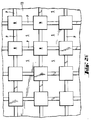
- FIG. 2 shows details of the surface condition of the anilox roller 13 2A, 2B, 2C and 2D show in the said Order of cup geometries in the form of domes, stump pyramids, pyramids and cylinders, the cell-bridge ratio being approximately 2: 1 (FIG. 2A) to is about 3: 1 ( Figure 2D).
- 2E shows (in plan view) a variant of FIG. 2B with partial bar recess. At a depth t of the well N of 10 ⁇ m there are partial depressions P of 5 ⁇ m in the web surfaces S. Depth, so that on the one hand the well N through the partial recesses P are connected to each other, but on the other hand still enough web area S as Contact surface for the ink squeegee is available. With the embodiment according to FIG. 2E, a better surface profile and thus achieve a better area filling, which increases the print quality means.
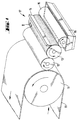
- FIG. 3 shows a perspective illustration of a heatable doctor blade 52, which is closed on both sides by elastic sealing profiles 32, 32 '.
- the sealing doctor is another sealing profile 32 '', 32 '' 'attached inside 52 divided into three separate chambers 35, 35 ', 35' ', each with its own Ink supply 56, 56 ', 56' 'and its own color level controller 53, 53', 53 '' have.
- the subdivision of the chambered doctor blade enables the separate chambers to feed with different inks, so that at the same time multicolored can be printed.
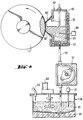
- FIG. 4 shows a section through the chambered doctor blade 52 from FIG. 3, fed via an ink tank 58, which via a fore / back pump 57 via a single Ink line 56 is connected to the doctor blade 52.
- the ink line 56 opens into the chambered doctor blade 52 at the lowest point of the ink filling 65 ', so that the fresh printing ink is always updated from below.
- the supply of the ink container 58 takes place via a feed line 59 Agitator 60 maintains the homogeneity of the ink 65.
- the Chamber squeegee 52 has ventilation devices 66 to avoid blistering in the ink filling 65 '.
- Both the ink tank 58 and the chambered doctor blade 52 can be heated by means of temperature control devices 69 and 67, keeping the temperature constant via control devices 70 and 68.
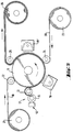
- a web material 10 (polyethylene, 20 .mu.m) is drawn off from a roll 21 and fed to an impression cylinder 11 via a deflection roll 22.
- a UV-curable laminating adhesive is applied to the web material 10 by means of a high-pressure roller 12.
- the supply of the high-pressure roller 12 with laminating adhesive takes place by means of an anilox roller 13 with a heatable doctor blade 52.
- a further web material 20 (polyamide, 60 ⁇ m) is then applied to the web material 10 coated with the reaction laminating adhesive, which is pulled off a roller 23 and by means of a Laminating roller 24 is applied to the adhesive-coated web material 10.
- the laminated composite material is then taken up on a roller 26 via a deflection roller 25.
- UV lamps 18, 18 ' are provided on the outer circumference of the impression cylinder 11 for curing the reaction laminating adhesive.
- the UV lamp 18 pre-hardens the reaction adhesive, care being taken to ensure that sufficient tack is still available when the second web material 20 is applied to achieve adhesive lamination.
- post-curing is then carried out by means of the UV lamp 18 '. It works with a web speed of the impression cylinder 11 of 150 m / min.
- a solvent-free UV-curable laminating adhesive based on epoxy resin with a viscosity at the working temperature of 60 ° C of 0.6 Pa ⁇ s is used.
- the application takes place over the entire area in an amount of 3 g / m 2 , which corresponds to an application thickness of approximately 3 ⁇ m.
- An anilox roller 13 with a geometry according to FIG. 2E is used, with a raster width of 170 and an N / S ratio of 3: 1 (here the web depressions are calculated as a web).
- the entire system is kept at a working temperature of 60 ° C by appropriate temperature control devices.
- Such one UV lamp 61 has a UV radiation source 63 with an energy density of 150 W / cm (axial), which is housed in a water-cooled housing 62.
- a water-cooled housing 62 in the Inside the housing are movable, also water-cooled reflectors 64, 64 ' provided that automatically in the event of faults, especially when the system is at a standstill between the radiation source 63 and the impression cylinder 11 (see FIG 5) so that overheating of the web material 10 or 10 and 20 (cf. Figure 5) is avoided.
- a control device (not shown) provided when the web speed of the counterpressure cylinder changes 11 causes an automatic adjustment of the radiation power.
Landscapes
- Printing Methods (AREA)
- Inking, Control Or Cleaning Of Printing Machines (AREA)
- Inks, Pencil-Leads, Or Crayons (AREA)
- Electrical Discharge Machining, Electrochemical Machining, And Combined Machining (AREA)
- Application Of Or Painting With Fluid Materials (AREA)
- Photosensitive Polymer And Photoresist Processing (AREA)
- Printing Plates And Materials Therefor (AREA)
- Manufacture Or Reproduction Of Printing Formes (AREA)
- Coating Apparatus (AREA)
Claims (19)
- Procédé pour appliquer des systèmes de liant, notamment de l'encre d'imprimerie sur une bande de matériau en typographie, l'application du système de liant sur la forme typographique d'un rouleau imprimeur s'effectuant au moyen d'un rouleau de trame,
caractérisé en ce queon applique un système de liant sans solvant au moyen d'un rouleau de trame qui comporte une trame de petits creux d'une profondeur ≤ 15 µm. - Procédé selon la revendication 1, caractérisé en ce que l'on utilise une encre d'imprimerie durcissable par rayonnement.
- Procédé selon la revendication 1, caractérisé en ce que l'on utilise une encre d'imprimerie durcissable par ultraviolet.
- Procédé selon la revendication 3, caractérisé en ce que l'on utilise une encre d'imprimerie à base d'acrylate ou de méthacrylate.
- Procédé selon la revendication 4, caractérisé en ce que l'on utilise une encre d'imprimerie ayant une teneur en pigment de 20 à 50 % en poids et une viscosité à 40 °C de 0,08 à 0,12 Pa.s et en ce que l'on traite cette encre à une température de 40 à 60 °C.
- Procédé selon la revendication 1, caractérisé en ce que l'on utilise comme liant sans solvant un adhésif de contrecollage durcissable par rayonnement, une seconde bande de matériau étant contrecollée sur la bande de matériau munie de l'adhésif et le durcissement par rayonnement de l'adhésif s'effectuant avant et/ou après l'opération de contrecollage.
- Dispositif d'application pour la typographie avec un cylindre à contre-pression (11) et un ou plusieurs rouleaux imprimeurs (12) qui sont alimentés en système de liant sans solvant chacun par l'intermédiaire d'une unité d'application de liant (17) avec un rouleau de trame (13),
caractérisé en ce quele rouleau de trame (13) comporte une trame de petits creux d'une profondeur (t) de 1 à 10 µm,le rouleau de trame (13) a un rapport petits creux / traverses de 8:1 à 1:1, et en ce quela largeur de trame du rouleau de trame (13) vaut de 170 à 280 L/cm. - Dispositif d'application selon la revendication 7, caractérisé en ce que la profondeur (t) des petits creux du rouleau de trame (13) vaut de 5 à 8 µm.
- Dispositif d'application selon l'une des revendications 7 à 8, caractérisé en ce que la largeur de trame du rouleau de trame (13) vaut de 180 à 240 L/cm.
- Dispositif d'application selon l'une des revendications 7 à 9, caractérisé en ce qu'un ou plusieurs dispositifs (18) destinés à fournir un rayonnement de grande énergie sur une bande de matériau (10) sont agencés à la périphérie du cylindre à contre-pression (11).
- Dispositif d'application selon la revendication 10, caractérisé en ce que les dispositifs (18) sont construits comme des émetteurs d'ultraviolets (61).
- Dispositif d'application selon la revendication 11, caractérisé en ce que les émetteurs d'ultraviolets (61) sont refroidis.
- Dispositif d'application selon la revendication 12, caractérisé en ce que les émetteurs d'ultraviolets (61) sont munis d'un boítier (62) refroidi par eau et de réflecteurs (64, 64') mobiles et refroidis par eau.
- Dispositif d'application selon l'une des revendications 7 à 13, caractérisé en ce que l'unité d'application (17) pour l'alimentation du rouleau de trame (13) en liant comporte une racle à compartiments (52) avec un régulateur de niveau de liant (53) et alimentée et vidée par un récipient (58) qui est relié à la racle à compartiments (52) par l'intermédiaire d'une pompe alternative (57) par un seul conduit de liant (56).
- Dispositif d'application selon la revendication 14, caractérisé en ce que le conduit de liant (56) débouche dans la racle à compartiments (52) au point le plus bas du remplissage de liant.
- Dispositif d'application selon la revendication 14 ou 15, caractérisé en ce que la racle à compartiments est construite comme une racle chauffante avec des profils d'étanchéité (32, 32') élastiques des deux côtés et avec des entrées et des sorties (56).
- Dispositif d'application selon la revendication 16, caractérisé en ce que la racle à compartiments (52) comporte à une certaine distance des profils d'étanchéité latéraux (32, 32') un ou plusieurs autres profils d'étanchéité (32'', 32'''), les compartiments (35, 35', 35'') ainsi formés comportant chacun une entrée de liant (56, 56', 56'') particulière et un régulateur de niveau (53, 53', 53'') particulier.
- Dispositif d'application selon l'une des revendications 14 à 17, caractérisé en ce que la racle à compartiments (52) comporte des dispositifs d'élimination d'air (66, 66', 66'') pour éviter la formation de bulles dans le liant.
- Rouleau de trame avec une trame de petits creux pour la mise en oeuvre du procédé selon l'une des revendications 1 à 6, caractérisé en ce quele rouleau de trame (13) comporte une trame de petits creux d'une profondeur (t) de 1 à 10 µm,le rouleau de trame (13) a un rapport petits creux / traverses de 8:1 à 1:1, et en ce quela largeur de trame du rouleau de trame (13) vaut de 170 à 280 L/cm.
Applications Claiming Priority (2)
| Application Number | Priority Date | Filing Date | Title |
|---|---|---|---|
| DE4137337A DE4137337A1 (de) | 1991-11-13 | 1991-11-13 | Hochdruckverfahren und auftragsvorrichtung zu seiner durchfuehrung |
| DE4137337 | 1991-11-13 |
Publications (3)
| Publication Number | Publication Date |
|---|---|
| EP0542190A2 EP0542190A2 (fr) | 1993-05-19 |
| EP0542190A3 EP0542190A3 (en) | 1993-08-11 |
| EP0542190B1 true EP0542190B1 (fr) | 1998-03-04 |
Family
ID=6444721
Family Applications (1)
| Application Number | Title | Priority Date | Filing Date |
|---|---|---|---|
| EP92119198A Revoked EP0542190B1 (fr) | 1991-11-13 | 1992-11-10 | Procédé d'impression en relief et applicateur |
Country Status (8)
| Country | Link |
|---|---|
| US (1) | US5671678A (fr) |
| EP (1) | EP0542190B1 (fr) |
| JP (1) | JP3270543B2 (fr) |
| AT (1) | ATE163597T1 (fr) |
| CA (1) | CA2082723A1 (fr) |
| DE (2) | DE4137337A1 (fr) |
| DK (1) | DK0542190T3 (fr) |
| ES (1) | ES2116305T3 (fr) |
Families Citing this family (62)
| Publication number | Priority date | Publication date | Assignee | Title |
|---|---|---|---|---|
| CA2122089A1 (fr) * | 1993-04-30 | 1994-10-31 | Glen H. Bayer, Jr. | Methode et dispositif pour l'application d'un revetement sur un substrat |
| FR2720976B1 (fr) * | 1994-06-08 | 1996-07-12 | Pechiney Emballage Alimentaire | Procédé d'impression par héliogravure avec des encres sans solvants. |
| WO1997019762A1 (fr) * | 1995-11-27 | 1997-06-05 | Ecosil Ecological Siliconize System P-200, S.L. | Dispositif d'application d'une pellicule de produit sur un support |
| DE19623349A1 (de) * | 1996-06-12 | 1997-12-18 | Baldwin Gegenheimer Gmbh | Temperierte Flüssigkeits-Übertragungsvorrichtung der graphischen Industrie |
| DE29702629U1 (de) * | 1997-02-15 | 1997-04-10 | Voith Sulzer Papiermaschinen GmbH, 89522 Heidenheim | Vorrichtung zum indirekten ein- oder beidseitigen Auftragen eines flüssigen Mediums auf eine laufende Warenbahn |
| JPH10226148A (ja) * | 1997-02-17 | 1998-08-25 | Heidelberger Druckmas Ag | 非吸収性の物質を多色印刷する方法 |
| DE19717524C2 (de) * | 1997-04-25 | 2002-04-04 | Roland Man Druckmasch | Farbwerk für eine Druckmaschine |
| EP0930161B1 (fr) * | 1998-01-19 | 2003-05-07 | Mohndruck Graphische Betriebe GmbH | Méthode et dispositf pour le revêtement de produits imprimés |
| IT1299142B1 (it) * | 1998-03-12 | 2000-02-29 | Innovapack Di Bagalini Giulio | Apparecchiatura di stampa flexografica du legno, pannello di fibra- legno e/o similari |
| EP0958920A1 (fr) * | 1998-05-22 | 1999-11-24 | Fischer & Krecke Gmbh & Co. | Machine à imprimer |
| GB9817194D0 (en) * | 1998-08-07 | 1998-10-07 | Hayneswood Engineering Sales L | Coating apparatus |
| IT1310184B1 (it) * | 1999-03-05 | 2002-02-11 | Ronflette Sa | Apparecchiatura per la deposizione di strati di smalto e simili susupporti ceramici. |
| JP2003502152A (ja) * | 1999-06-18 | 2003-01-21 | ボイス ペ−パ− パテント ゲ−エムベ−ハ− | コーティング装置用ロール |
| JP3473513B2 (ja) * | 1999-07-27 | 2003-12-08 | 東洋製罐株式会社 | 缶胴への印刷方法 |
| DE19937468A1 (de) * | 1999-08-07 | 2001-03-08 | Roland Man Druckmasch | Vorrichtung zum Temperieren von Beschichtungsmedien |
| LU90470B1 (fr) * | 1999-10-29 | 2001-04-30 | Cabinet Erman S A R L | Outillage d'impression |
| DE10001764A1 (de) * | 2000-01-18 | 2001-08-02 | Koenig & Bauer Ag | Farbauftrageinrichtung |
| GB0020279D0 (en) * | 2000-08-18 | 2000-10-04 | Mead Corp | Substrate coating |
| US6626096B1 (en) * | 2000-11-09 | 2003-09-30 | Stephen P. Shoemaker, Jr. | Redemption ticket maker |
| DE10152461B4 (de) * | 2000-11-10 | 2012-05-03 | Heidelberger Druckmaschinen Ag | Verfahren zur Aufbereitung von Druckfarbe einer Druckmaschine und entsprechende Verwendungen einer Druckmaschine |
| US20030091807A1 (en) * | 2001-11-05 | 2003-05-15 | The Procter & Gamble Company | Stretch composites and methods of making the composite |
| JP2004058611A (ja) * | 2002-07-31 | 2004-02-26 | Denso Corp | スパークプラグ用絶縁碍子の印刷装置及び印刷方法 |
| DE10236781B4 (de) * | 2002-08-14 | 2009-11-19 | Manroland Ag | Beschichtungseinrichtung für eine Druck- oder Beschichtungsmaschine |
| JP4007335B2 (ja) * | 2003-04-17 | 2007-11-14 | 株式会社村田製作所 | グラビアロール、グラビア印刷機および積層セラミック電子部品の製造方法 |
| US20040209197A1 (en) * | 2003-04-17 | 2004-10-21 | Murata Manufacturing Co., Ltd. | Photogravure press and method for manufacturing multilayer-ceramic electronic component |
| US7658811B2 (en) * | 2004-03-29 | 2010-02-09 | The Procter & Gamble Company | Letterpress application of elastomeric compositions |
| US7820875B2 (en) | 2004-03-29 | 2010-10-26 | The Procter & Gamble Company | Disposable absorbent articles being adaptable to wearer's anatomy |
| US8198200B2 (en) | 2004-03-29 | 2012-06-12 | The Procter & Gamble Company | Web materials having both plastic and elastic properties |
| US20050215972A1 (en) * | 2004-03-29 | 2005-09-29 | Roe Donald C | Disposable absorbent articles with zones comprising elastomeric components |
| US8568382B2 (en) | 2004-03-29 | 2013-10-29 | The Procter & Gamble Company | Disposable absorbent articles having co-elongation |
| TWI332438B (en) * | 2004-07-08 | 2010-11-01 | Murata Manufacturing Co | Photogravure printing machine, manufacturing method of multilayer ceramic electronic device using the photogravure printing machine and gravure roll |
| DE102004042266A1 (de) * | 2004-09-01 | 2006-03-02 | Koenig & Bauer Ag | Verfahren zum Betreiben eines Kurzfarbwerkes eine Druckmaschine |
| DE102004063190A1 (de) * | 2004-12-29 | 2006-07-13 | Man Roland Druckmaschinen Ag | Vorrichtung zum Kleberauftrag für Kaltfolienprägung |
| US7520978B2 (en) * | 2005-06-17 | 2009-04-21 | Philips Lumileds Lighting Co., Llc | Fluid purification system with ultra violet light emitters |
| DE102006048487A1 (de) * | 2006-10-11 | 2008-04-17 | Heidelberger Druckmaschinen Ag | Farbkasten einer Druckmaschine |
| DE102007018130B4 (de) * | 2007-04-16 | 2010-06-17 | Fischer & Krecke Gmbh | Farbbehälter |
| JP2008279680A (ja) * | 2007-05-11 | 2008-11-20 | Kyodo Printing Co Ltd | フレキソ印刷方法、該方法に用いる印刷装置及び該方法で製造された印刷物 |
| JP5284603B2 (ja) * | 2007-05-31 | 2013-09-11 | 株式会社小森コーポレーション | 枚葉印刷機 |
| DE102007027384A1 (de) * | 2007-06-11 | 2009-03-12 | Windmöller & Hölscher Kg | Farbkammerrakel in einem Farbwerk einer Rotationsdruckmaschine sowie Verfahren zur Herstellung einer Farbkammerrakel |
| DE102007030197A1 (de) * | 2007-06-27 | 2009-01-02 | Hauni Maschinenbau Ag | Druckwerk einer Maschine der Tabak verarbeitenden Industrie |
| DE102008028949B4 (de) * | 2007-06-28 | 2012-04-12 | Ryobi Ltd. | Oberflächenbehandlungsvorrichtung für ein bedrucktes Blatt |
| DK176626B1 (da) * | 2007-08-21 | 2008-12-01 | Tresu Anlaeg As | Pakning til kammerrakel |
| DE102007052767A1 (de) * | 2007-11-06 | 2009-05-07 | Manroland Ag | Verfahren und Vorrichtung zum Verarbeiten von unter Strahlung härtenden Farben und Lacken in einer Verarbeitungsmaschine |
| JP4960215B2 (ja) * | 2007-12-28 | 2012-06-27 | パナソニック株式会社 | 金属箔負極集電体加工用ローラ及び金属箔負極集電体加工方法 |
| DE102008019434B4 (de) * | 2008-04-17 | 2013-08-22 | Hauni Maschinenbau Ag | Beleimung von Materialstreifen der Tabak verarbeitenden Industrie |
| US20100144080A1 (en) * | 2008-06-02 | 2010-06-10 | Solexel, Inc. | Method and apparatus to transfer coat uneven surface |
| US8002936B2 (en) * | 2008-10-23 | 2011-08-23 | Xerox Corporation | Dual-web method for fixing a radiation-curable gel-ink image on a substrate |
| US8152290B2 (en) | 2008-11-26 | 2012-04-10 | Xerox Corporation | Customization of curable ink prints by molding |
| CN102264545B (zh) * | 2008-12-22 | 2015-05-20 | 技术解决顾问有限公司 | 可进行湿压湿印刷的柔性版印刷方法 |
| JP2010012790A (ja) * | 2009-08-28 | 2010-01-21 | Mitsubishi Plastics Inc | ポリ乳酸系2軸延伸積層フィルム |
| US20110192297A1 (en) * | 2010-02-11 | 2011-08-11 | Mikhail Laksin | Printing system having a raised image printing cylinder |
| DE102010019468A1 (de) * | 2010-05-05 | 2011-11-10 | Giesecke & Devrient Gmbh | Flexodruckwerk, Flexodruckverfahren und daraus erhältliches Druckerzeugnis |
| US20120249669A1 (en) * | 2011-04-01 | 2012-10-04 | Merritt Jr James Howard | System and method for printing on tape |
| DE102013218961A1 (de) * | 2013-09-20 | 2015-03-26 | Dietmar Neuhaus | Vorrichtung und Verfahren zum Übertragen von fließfähigen Drucksubstanzen auf einen Bedruckstoff |
| EP3074233B1 (fr) * | 2013-11-27 | 2017-11-22 | Merck Patent GmbH | Procédé d'impression par rotative |
| US10471752B2 (en) * | 2016-08-08 | 2019-11-12 | Palo Alto Research Center Incorporated | Anilox patterns and doctor blades for metering high viscosity pigmented inks |
| JP7118403B2 (ja) * | 2018-05-10 | 2022-08-16 | 株式会社タカゾノ | インクジェット印刷装置 |
| JP7426067B2 (ja) * | 2019-10-28 | 2024-02-01 | 日本電子精機株式会社 | インク供給ロールの洗浄方法とそれに使用するクリーニングシート |
| EP4182170B1 (fr) | 2021-02-18 | 2024-03-06 | Koenig & Bauer AG | Systèmes d'alimentation en encre et procédés pour alimenter en encre d'impression une unité d'encrage d'un groupe d'impression en creux, et groupe d'impression en creux et procédé de fonctionnement d'un système d'alimentation en encre |
| DE102021103845A1 (de) | 2021-02-18 | 2022-08-18 | Koenig & Bauer Ag | Vorrichtung zur Bereitstellung von Druckfarbe sowie Druckwerk mit einer solchen Vorrichtung |
| GB2631676A (en) * | 2023-04-12 | 2025-01-15 | Short Brothers Plc | Apparatus and method for the manufacture of noodles |
| DE102024119062A1 (de) * | 2024-07-04 | 2026-01-08 | Matthews International GmbH | Rasterwalze, Druckwerk mit Rasterwalze und Verfahren zur Herstellung einer Rasterwalze |
Family Cites Families (20)
| Publication number | Priority date | Publication date | Assignee | Title |
|---|---|---|---|---|
| GB1307166A (en) * | 1971-07-07 | 1973-02-14 | Pamarco Inc | Flexographic printing press |
| US3950650A (en) * | 1974-03-25 | 1976-04-13 | Thermogenics Of New York, Inc. | Ink curing and drying apparatus |
| US4007682A (en) * | 1974-04-24 | 1977-02-15 | Xerox Corporation | Reverse angle mounted ink-splitting doctor blade |
| US4009657A (en) * | 1975-02-25 | 1977-03-01 | Scott Paper Company | Apparatus for applying fluid to an intaglio roll for transfer to a soft, absorbent fibrous web |
| US4113895A (en) * | 1976-11-19 | 1978-09-12 | American Can Company | Method for producing multilayered coated substrate |
| US4158333A (en) * | 1978-05-01 | 1979-06-19 | Anpa Research Institute | Inking baffle for rotary newspaper presses |
| US4301583A (en) * | 1979-02-15 | 1981-11-24 | Consolidated Engravers Corporation | Fluid metering roller |
| JPS5714663A (en) * | 1980-06-30 | 1982-01-25 | Dainippon Printing Co Ltd | Offset printing ink and offset printing process |
| JPS5759968A (en) * | 1980-09-27 | 1982-04-10 | Dainippon Printing Co Ltd | Screen printing ink and screen color printing method |
| JPS5759967A (en) * | 1980-09-27 | 1982-04-10 | Dainippon Printing Co Ltd | Screen printing ink and screen printing method |
| JPS57152992A (en) * | 1981-03-19 | 1982-09-21 | Kamaya Kagaku Kogyo Kk | Decoration of brilliant metallic letter and picture, etc. |
| JPS59199886A (ja) * | 1983-04-22 | 1984-11-13 | 中塚株式会社 | 布帛に複合模様を形成する方法 |
| US4569864A (en) * | 1983-06-30 | 1986-02-11 | Acumeter Laboratories, Inc. | Roll coating applicator and adhesive coatings and the like and process of coating |
| US4860652A (en) * | 1986-05-24 | 1989-08-29 | Kabushikigaisha Tokyo Kikai Seisakusho | Mesh roller for planography |
| DE3787895T2 (de) * | 1987-10-05 | 1994-05-19 | Kinyosha Kk | Tintenrolle für druckpressen und verfahren zur herstellung. |
| US4862799A (en) * | 1987-11-13 | 1989-09-05 | Rockwell International Corporation | Copper coated anodized aluminum ink metering roller |
| GB8801537D0 (en) * | 1988-01-23 | 1988-02-24 | Crown Wallcoverings Ltd | Engraved printing rolls |
| DE3832216C1 (fr) * | 1988-09-22 | 1990-05-31 | Man Roland Druckmaschinen Ag, 6050 Offenbach, De | |
| US5093180A (en) * | 1989-05-02 | 1992-03-03 | Union Carbide Coatings Service Technology Corporation | Liquid transfer articles and method for producing them |
| DE3938449A1 (de) * | 1989-11-18 | 1991-05-23 | Roland Man Druckmasch | Druckwerk |
-
1991
- 1991-11-13 DE DE4137337A patent/DE4137337A1/de not_active Withdrawn
-
1992
- 1992-11-10 DE DE59209214T patent/DE59209214D1/de not_active Expired - Fee Related
- 1992-11-10 ES ES92119198T patent/ES2116305T3/es not_active Expired - Lifetime
- 1992-11-10 DK DK92119198T patent/DK0542190T3/da active
- 1992-11-10 EP EP92119198A patent/EP0542190B1/fr not_active Revoked
- 1992-11-10 AT AT92119198T patent/ATE163597T1/de not_active IP Right Cessation
- 1992-11-12 CA CA002082723A patent/CA2082723A1/fr not_active Abandoned
- 1992-11-13 JP JP30364292A patent/JP3270543B2/ja not_active Expired - Fee Related
-
1995
- 1995-10-11 US US08/541,090 patent/US5671678A/en not_active Expired - Fee Related
Also Published As
| Publication number | Publication date |
|---|---|
| ATE163597T1 (de) | 1998-03-15 |
| DE4137337A1 (de) | 1993-05-19 |
| US5671678A (en) | 1997-09-30 |
| CA2082723A1 (fr) | 1993-05-14 |
| JP3270543B2 (ja) | 2002-04-02 |
| ES2116305T3 (es) | 1998-07-16 |
| DE59209214D1 (de) | 1998-04-09 |
| DK0542190T3 (da) | 1998-12-28 |
| EP0542190A2 (fr) | 1993-05-19 |
| JPH0640141A (ja) | 1994-02-15 |
| EP0542190A3 (en) | 1993-08-11 |
Similar Documents
| Publication | Publication Date | Title |
|---|---|---|
| EP0542190A2 (fr) | Procédé d'impression en relief et applicateur | |
| EP3274174B1 (fr) | Procédé et dispositif d'application d'une feuille | |
| EP2172347B1 (fr) | Film de transfert et procédé de transfert de films à froid | |
| DE10362054B4 (de) | Offsetdruckverfahren und Druckerzeugnis | |
| EP0164001B1 (fr) | Méthode et dispositif d'impression à sec d'un article par l'utilisation d'une feuille à gaufrer à chaud | |
| EP0262475A2 (fr) | Machine pour l'impression | |
| DE102009002228A1 (de) | Lackierwerk einer Rollen-Rotations-Offsetdruckmaschine | |
| EP0963287B1 (fr) | Forme pour la realisation sur rotative d'une impression, d'un recouvrement ou d'une empreinte sur des materiaux en forme de bandes, et procede de realisation d'une telle forme | |
| CH694582A5 (de) | Kurzfarbwerk. | |
| EP0844100B1 (fr) | Blanchet d'impression offset | |
| EP0339409A2 (fr) | Procédé et appareil pour l'impression flexographique | |
| DE102009007002A1 (de) | Bogendruckmaschine | |
| DE102008047096A1 (de) | Drucktuch für ein Kaltfolientransferverfahren | |
| DE19750259B4 (de) | Verfahren und Druckmaschine zum mehrfarbigen Bedrucken von nichtsaugendem Material | |
| DE102012218840A1 (de) | Folientransferverfahren | |
| DE10360050B3 (de) | Offsetdruckverfahren und Druckerzeugnis | |
| EP0352520B1 (fr) | Procédé d'impression offset | |
| DE102008054411A1 (de) | Beschichtungseinrichtung mit Kurzfarbwerk | |
| EP1798033A2 (fr) | Laminage avec un dispositif de gaufrage | |
| DE102007059915A1 (de) | Vorrichtung und Verfahren zum Beschichten von Bedruckstoffen in einer Rotationsdruckmaschine | |
| DE3535993A1 (de) | Flexodruckmaschine oder zeitungsrotationsmaschine | |
| EP0051710B1 (fr) | Procédé de préparation de revêtement de paroi ou de sol ayant un relief et dispositif pour la mise en oeuvre du procédé | |
| DE10106385A1 (de) | Foliendruckverfahren und Vorrichtung hierzu | |
| DE102009002822A1 (de) | Betrieb eines Kaltfolienaggregates mit Kleberauftrag | |
| EP1211067B1 (fr) | Procédé pour créer des impressions avec apparence plastique dans des machines d'impression offset |
Legal Events
| Date | Code | Title | Description |
|---|---|---|---|
| PUAI | Public reference made under article 153(3) epc to a published international application that has entered the european phase |
Free format text: ORIGINAL CODE: 0009012 |
|
| AK | Designated contracting states |
Kind code of ref document: A2 Designated state(s): AT BE CH DE DK ES FR GB GR IE IT LI LU NL PT SE |
|
| PUAL | Search report despatched |
Free format text: ORIGINAL CODE: 0009013 |
|
| AK | Designated contracting states |
Kind code of ref document: A3 Designated state(s): AT BE CH DE DK ES FR GB GR IE IT LI LU NL PT SE |
|
| 17P | Request for examination filed |
Effective date: 19931223 |
|
| 17Q | First examination report despatched |
Effective date: 19951019 |
|
| RIN1 | Information on inventor provided before grant (corrected) |
Inventor name: DRILLER, FRANZ-JOSEF Inventor name: BOLTE, GEORG, DR. |
|
| RAP1 | Party data changed (applicant data changed or rights of an application transferred) |
Owner name: DRILLER, FRANZ-JOSEF Owner name: NOELLE, LUTZ Owner name: BOLTE, GEORG, DR. |
|
| GRAG | Despatch of communication of intention to grant |
Free format text: ORIGINAL CODE: EPIDOS AGRA |
|
| GRAH | Despatch of communication of intention to grant a patent |
Free format text: ORIGINAL CODE: EPIDOS IGRA |
|
| GRAH | Despatch of communication of intention to grant a patent |
Free format text: ORIGINAL CODE: EPIDOS IGRA |
|
| GRAA | (expected) grant |
Free format text: ORIGINAL CODE: 0009210 |
|
| AK | Designated contracting states |
Kind code of ref document: B1 Designated state(s): AT BE CH DE DK ES FR GB GR IE IT LI LU NL PT SE |
|
| REF | Corresponds to: |
Ref document number: 163597 Country of ref document: AT Date of ref document: 19980315 Kind code of ref document: T |
|
| REG | Reference to a national code |
Ref country code: CH Ref legal event code: EP |
|
| REF | Corresponds to: |
Ref document number: 59209214 Country of ref document: DE Date of ref document: 19980409 |
|
| ITF | It: translation for a ep patent filed | ||
| GBT | Gb: translation of ep patent filed (gb section 77(6)(a)/1977) |
Effective date: 19980522 |
|
| ET | Fr: translation filed | ||
| REG | Reference to a national code |
Ref country code: IE Ref legal event code: FG4D Free format text: 79100 |
|
| REG | Reference to a national code |
Ref country code: ES Ref legal event code: FG2A Ref document number: 2116305 Country of ref document: ES Kind code of ref document: T3 |
|
| REG | Reference to a national code |
Ref country code: PT Ref legal event code: SC4A Free format text: AVAILABILITY OF NATIONAL TRANSLATION Effective date: 19980520 |
|
| REG | Reference to a national code |
Ref country code: CH Ref legal event code: NV Representative=s name: LUCHS & PARTNER PATENTANWAELTE |
|
| PLBQ | Unpublished change to opponent data |
Free format text: ORIGINAL CODE: EPIDOS OPPO |
|
| PLBQ | Unpublished change to opponent data |
Free format text: ORIGINAL CODE: EPIDOS OPPO |
|
| PLBI | Opposition filed |
Free format text: ORIGINAL CODE: 0009260 |
|
| PLAV | Examination of admissibility of opposition |
Free format text: ORIGINAL CODE: EPIDOS OPEX |
|
| REG | Reference to a national code |
Ref country code: DK Ref legal event code: T3 |
|
| PLAV | Examination of admissibility of opposition |
Free format text: ORIGINAL CODE: EPIDOS OPEX |
|
| 26 | Opposition filed |
Opponent name: PRAXAIR SURFACE TECHNOLOGIES (EUROPE) S.A. Effective date: 19981202 Opponent name: SENGEWALD VERPACKUNGEN GMBH Effective date: 19981204 |
|
| PLBF | Reply of patent proprietor to notice(s) of opposition |
Free format text: ORIGINAL CODE: EPIDOS OBSO |
|
| NLR1 | Nl: opposition has been filed with the epo |
Opponent name: PRAXAIR SURFACE TECHNOLOGIES (EUROPE) S.A. Opponent name: SENGEWALD VERPACKUNGEN GMBH |
|
| PLBF | Reply of patent proprietor to notice(s) of opposition |
Free format text: ORIGINAL CODE: EPIDOS OBSO |
|
| PLBF | Reply of patent proprietor to notice(s) of opposition |
Free format text: ORIGINAL CODE: EPIDOS OBSO |
|
| PGFP | Annual fee paid to national office [announced via postgrant information from national office to epo] |
Ref country code: GB Payment date: 20000509 Year of fee payment: 8 |
|
| REG | Reference to a national code |
Ref country code: FR Ref legal event code: ST |
|
| REG | Reference to a national code |
Ref country code: FR Ref legal event code: RN |
|
| PG25 | Lapsed in a contracting state [announced via postgrant information from national office to epo] |
Ref country code: GB Free format text: LAPSE BECAUSE OF NON-PAYMENT OF DUE FEES Effective date: 20001110 |
|
| REG | Reference to a national code |
Ref country code: FR Ref legal event code: FC |
|
| PGFP | Annual fee paid to national office [announced via postgrant information from national office to epo] |
Ref country code: AT Payment date: 20010528 Year of fee payment: 9 |
|
| GBPC | Gb: european patent ceased through non-payment of renewal fee |
Effective date: 20001110 |
|
| PLAW | Interlocutory decision in opposition |
Free format text: ORIGINAL CODE: EPIDOS IDOP |
|
| APAC | Appeal dossier modified |
Free format text: ORIGINAL CODE: EPIDOS NOAPO |
|
| APAE | Appeal reference modified |
Free format text: ORIGINAL CODE: EPIDOS REFNO |
|
| APAC | Appeal dossier modified |
Free format text: ORIGINAL CODE: EPIDOS NOAPO |
|
| PGFP | Annual fee paid to national office [announced via postgrant information from national office to epo] |
Ref country code: DE Payment date: 20020510 Year of fee payment: 10 |
|
| PGFP | Annual fee paid to national office [announced via postgrant information from national office to epo] |
Ref country code: PT Payment date: 20020513 Year of fee payment: 10 Ref country code: ES Payment date: 20020513 Year of fee payment: 10 |
|
| PGFP | Annual fee paid to national office [announced via postgrant information from national office to epo] |
Ref country code: IE Payment date: 20020514 Year of fee payment: 10 Ref country code: CH Payment date: 20020514 Year of fee payment: 10 |
|
| PGFP | Annual fee paid to national office [announced via postgrant information from national office to epo] |
Ref country code: DK Payment date: 20020515 Year of fee payment: 10 |
|
| PGFP | Annual fee paid to national office [announced via postgrant information from national office to epo] |
Ref country code: SE Payment date: 20020516 Year of fee payment: 10 Ref country code: GR Payment date: 20020516 Year of fee payment: 10 |
|
| PGFP | Annual fee paid to national office [announced via postgrant information from national office to epo] |
Ref country code: FR Payment date: 20020527 Year of fee payment: 10 Ref country code: BE Payment date: 20020527 Year of fee payment: 10 |
|
| PGFP | Annual fee paid to national office [announced via postgrant information from national office to epo] |
Ref country code: NL Payment date: 20020531 Year of fee payment: 10 |
|
| PGFP | Annual fee paid to national office [announced via postgrant information from national office to epo] |
Ref country code: LU Payment date: 20020604 Year of fee payment: 10 |
|
| PG25 | Lapsed in a contracting state [announced via postgrant information from national office to epo] |
Ref country code: LU Free format text: LAPSE BECAUSE OF NON-PAYMENT OF DUE FEES Effective date: 20021110 Ref country code: AT Free format text: LAPSE BECAUSE OF NON-PAYMENT OF DUE FEES Effective date: 20021110 |
|
| PG25 | Lapsed in a contracting state [announced via postgrant information from national office to epo] |
Ref country code: SE Free format text: LAPSE BECAUSE OF NON-PAYMENT OF DUE FEES Effective date: 20021111 Ref country code: IE Free format text: LAPSE BECAUSE OF NON-PAYMENT OF DUE FEES Effective date: 20021111 Ref country code: ES Free format text: LAPSE BECAUSE OF NON-PAYMENT OF DUE FEES Effective date: 20021111 |
|
| PG25 | Lapsed in a contracting state [announced via postgrant information from national office to epo] |
Ref country code: LI Free format text: LAPSE BECAUSE OF NON-PAYMENT OF DUE FEES Effective date: 20021130 Ref country code: CH Free format text: LAPSE BECAUSE OF NON-PAYMENT OF DUE FEES Effective date: 20021130 Ref country code: BE Free format text: LAPSE BECAUSE OF NON-PAYMENT OF DUE FEES Effective date: 20021130 |
|
| PG25 | Lapsed in a contracting state [announced via postgrant information from national office to epo] |
Ref country code: DK Free format text: LAPSE BECAUSE OF NON-PAYMENT OF DUE FEES Effective date: 20021231 |
|
| BERE | Be: lapsed |
Owner name: *DRILLER FRANZ-JOSEF Effective date: 20021130 Owner name: *NOLLE LUTZ Effective date: 20021130 Owner name: *BOLTE GEORG Effective date: 20021130 |
|
| PG25 | Lapsed in a contracting state [announced via postgrant information from national office to epo] |
Ref country code: PT Free format text: LAPSE BECAUSE OF NON-PAYMENT OF DUE FEES Effective date: 20030531 |
|
| PG25 | Lapsed in a contracting state [announced via postgrant information from national office to epo] |
Ref country code: NL Free format text: LAPSE BECAUSE OF NON-PAYMENT OF DUE FEES Effective date: 20030601 |
|
| PG25 | Lapsed in a contracting state [announced via postgrant information from national office to epo] |
Ref country code: DE Free format text: LAPSE BECAUSE OF NON-PAYMENT OF DUE FEES Effective date: 20030603 |
|
| PG25 | Lapsed in a contracting state [announced via postgrant information from national office to epo] |
Ref country code: GR Free format text: LAPSE BECAUSE OF NON-PAYMENT OF DUE FEES Effective date: 20030609 |
|
| EUG | Se: european patent has lapsed | ||
| REG | Reference to a national code |
Ref country code: DK Ref legal event code: EBP |
|
| REG | Reference to a national code |
Ref country code: CH Ref legal event code: PL |
|
| PG25 | Lapsed in a contracting state [announced via postgrant information from national office to epo] |
Ref country code: FR Free format text: LAPSE BECAUSE OF NON-PAYMENT OF DUE FEES Effective date: 20030731 |
|
| NLV4 | Nl: lapsed or anulled due to non-payment of the annual fee |
Effective date: 20030601 |
|
| REG | Reference to a national code |
Ref country code: PT Ref legal event code: MM4A Free format text: LAPSE DUE TO NON-PAYMENT OF FEES Effective date: 20030531 |
|
| REG | Reference to a national code |
Ref country code: IE Ref legal event code: MM4A |
|
| REG | Reference to a national code |
Ref country code: FR Ref legal event code: ST |
|
| PLBQ | Unpublished change to opponent data |
Free format text: ORIGINAL CODE: EPIDOS OPPO |
|
| PLAB | Opposition data, opponent's data or that of the opponent's representative modified |
Free format text: ORIGINAL CODE: 0009299OPPO |
|
| PLBI | Opposition filed |
Free format text: ORIGINAL CODE: 0009260 |
|
| 26 | Opposition filed |
Opponent name: PRAXAIRSURFACETECHNOLOGIES (EUROPE) S.A. Effective date: 19981202 Opponent name: KOBUSCH-SENGEWALD GMBH & CO.KG. Effective date: 20030401 |
|
| REG | Reference to a national code |
Ref country code: ES Ref legal event code: FD2A Effective date: 20031213 |
|
| APBU | Appeal procedure closed |
Free format text: ORIGINAL CODE: EPIDOSNNOA9O |
|
| PLBQ | Unpublished change to opponent data |
Free format text: ORIGINAL CODE: EPIDOS OPPO |
|
| PLAB | Opposition data, opponent's data or that of the opponent's representative modified |
Free format text: ORIGINAL CODE: 0009299OPPO |
|
| R26 | Opposition filed (corrected) |
Opponent name: PRAXAIRSURFACETECHNOLOGIES (EUROPE) S.A. Effective date: 19981202 Opponent name: KOBUSCH-SENGEWALD GMBH & CO.KG. Effective date: 20030401 |
|
| RDAF | Communication despatched that patent is revoked |
Free format text: ORIGINAL CODE: EPIDOSNREV1 |
|
| RDAG | Patent revoked |
Free format text: ORIGINAL CODE: 0009271 |
|
| STAA | Information on the status of an ep patent application or granted ep patent |
Free format text: STATUS: PATENT REVOKED |
|
| APAH | Appeal reference modified |
Free format text: ORIGINAL CODE: EPIDOSCREFNO |
|
| 27W | Patent revoked |
Effective date: 20050520 |