EP0542431A1 - Dispositif pour enrouler une couche en forme de bande - Google Patents
Dispositif pour enrouler une couche en forme de bande Download PDFInfo
- Publication number
- EP0542431A1 EP0542431A1 EP92309479A EP92309479A EP0542431A1 EP 0542431 A1 EP0542431 A1 EP 0542431A1 EP 92309479 A EP92309479 A EP 92309479A EP 92309479 A EP92309479 A EP 92309479A EP 0542431 A1 EP0542431 A1 EP 0542431A1
- Authority
- EP
- European Patent Office
- Prior art keywords
- drum
- rocking
- axis
- base
- attaching roller
- Prior art date
- Legal status (The legal status is an assumption and is not a legal conclusion. Google has not performed a legal analysis and makes no representation as to the accuracy of the status listed.)
- Granted
Links
Images


Classifications
-
- B—PERFORMING OPERATIONS; TRANSPORTING
- B29—WORKING OF PLASTICS; WORKING OF SUBSTANCES IN A PLASTIC STATE IN GENERAL
- B29C—SHAPING OR JOINING OF PLASTICS; SHAPING OF MATERIAL IN A PLASTIC STATE, NOT OTHERWISE PROVIDED FOR; AFTER-TREATMENT OF THE SHAPED PRODUCTS, e.g. REPAIRING
- B29C70/00—Shaping composites, i.e. plastics material comprising reinforcements, fillers or preformed parts, e.g. inserts
- B29C70/04—Shaping composites, i.e. plastics material comprising reinforcements, fillers or preformed parts, e.g. inserts comprising reinforcements only, e.g. self-reinforcing plastics
- B29C70/28—Shaping operations therefor
- B29C70/30—Shaping by lay-up, i.e. applying fibres, tape or broadsheet on a mould, former or core; Shaping by spray-up, i.e. spraying of fibres on a mould, former or core
- B29C70/32—Shaping by lay-up, i.e. applying fibres, tape or broadsheet on a mould, former or core; Shaping by spray-up, i.e. spraying of fibres on a mould, former or core on a rotating mould, former or core
-
- B—PERFORMING OPERATIONS; TRANSPORTING
- B29—WORKING OF PLASTICS; WORKING OF SUBSTANCES IN A PLASTIC STATE IN GENERAL
- B29C—SHAPING OR JOINING OF PLASTICS; SHAPING OF MATERIAL IN A PLASTIC STATE, NOT OTHERWISE PROVIDED FOR; AFTER-TREATMENT OF THE SHAPED PRODUCTS, e.g. REPAIRING
- B29C53/00—Shaping by bending, folding, twisting, straightening or flattening; Apparatus therefor
- B29C53/80—Component parts, details or accessories; Auxiliary operations
- B29C53/8008—Component parts, details or accessories; Auxiliary operations specially adapted for winding and joining
- B29C53/8016—Storing, feeding or applying winding materials, e.g. reels, thread guides, tensioners
-
- B—PERFORMING OPERATIONS; TRANSPORTING
- B29—WORKING OF PLASTICS; WORKING OF SUBSTANCES IN A PLASTIC STATE IN GENERAL
- B29C—SHAPING OR JOINING OF PLASTICS; SHAPING OF MATERIAL IN A PLASTIC STATE, NOT OTHERWISE PROVIDED FOR; AFTER-TREATMENT OF THE SHAPED PRODUCTS, e.g. REPAIRING
- B29C70/00—Shaping composites, i.e. plastics material comprising reinforcements, fillers or preformed parts, e.g. inserts
- B29C70/04—Shaping composites, i.e. plastics material comprising reinforcements, fillers or preformed parts, e.g. inserts comprising reinforcements only, e.g. self-reinforcing plastics
- B29C70/28—Shaping operations therefor
- B29C70/30—Shaping by lay-up, i.e. applying fibres, tape or broadsheet on a mould, former or core; Shaping by spray-up, i.e. spraying of fibres on a mould, former or core
- B29C70/38—Automated lay-up, e.g. using robots, laying filaments according to predetermined patterns
- B29C70/386—Automated tape laying [ATL]
-
- B—PERFORMING OPERATIONS; TRANSPORTING
- B29—WORKING OF PLASTICS; WORKING OF SUBSTANCES IN A PLASTIC STATE IN GENERAL
- B29D—PRODUCING PARTICULAR ARTICLES FROM PLASTICS OR FROM SUBSTANCES IN A PLASTIC STATE
- B29D30/00—Producing pneumatic or solid tyres or parts thereof
- B29D30/06—Pneumatic tyres or parts thereof (e.g. produced by casting, moulding, compression moulding, injection moulding, centrifugal casting)
- B29D30/08—Building tyres
- B29D30/20—Building tyres by the flat-tyre method, i.e. building on cylindrical drums
- B29D30/30—Applying the layers; Guiding or stretching the layers during application
- B29D30/3035—Applying the layers; Guiding or stretching the layers during application by feeding a continuous band and moving it back and forth (zig-zag) to form an annular element
-
- B—PERFORMING OPERATIONS; TRANSPORTING
- B29—WORKING OF PLASTICS; WORKING OF SUBSTANCES IN A PLASTIC STATE IN GENERAL
- B29D—PRODUCING PARTICULAR ARTICLES FROM PLASTICS OR FROM SUBSTANCES IN A PLASTIC STATE
- B29D30/00—Producing pneumatic or solid tyres or parts thereof
- B29D30/06—Pneumatic tyres or parts thereof (e.g. produced by casting, moulding, compression moulding, injection moulding, centrifugal casting)
- B29D30/52—Unvulcanised treads, e.g. on used tyres; Retreading
- B29D30/58—Applying bands of rubber treads, i.e. applying camel backs
- B29D30/60—Applying bands of rubber treads, i.e. applying camel backs by winding narrow strips
-
- B—PERFORMING OPERATIONS; TRANSPORTING
- B29—WORKING OF PLASTICS; WORKING OF SUBSTANCES IN A PLASTIC STATE IN GENERAL
- B29D—PRODUCING PARTICULAR ARTICLES FROM PLASTICS OR FROM SUBSTANCES IN A PLASTIC STATE
- B29D30/00—Producing pneumatic or solid tyres or parts thereof
- B29D30/06—Pneumatic tyres or parts thereof (e.g. produced by casting, moulding, compression moulding, injection moulding, centrifugal casting)
- B29D30/70—Annular breakers
Definitions
- the present invention relates to a narrow belt-shaped member winding apparatus for winding a narrow belt-shaped member in zigzag around a drum by supplying to the rotating drum the belt-shaped member being swung in axial directions of the drum.
- an apparatus for winding a rubber-coated cord sheet in zigzag around a drum has been known, for example, as disclosed in United States Patent Specification No. 3,721,599.
- the disclosed apparatus includes a guide tube extending along a normal to the outer surface of a drum and having a forward end adjacent the outer surface of the drum, and reciprocative motion means for reciprocatively moving the guide tube in the axial directions of the drum.
- a rubber-coated cord sheet is supplied through the guide tube which is swung or reciprocatively moved to wind the sheet in zigzag around the drum.
- the proposed apparatus comprises a support base, and moving means for moving the support base substantially along an axis of the semimanufactured tire to maintain a distance from it at a constant value.
- the apparatus further comprises an attaching roller supported on the support base rotatably about an axis substantially in parallel with the axis of the semimanufactured tire for urging and attaching a supplied cord to the semimanufactured tire after being wound partially around the attaching roller.
- a cord is supplied to the attaching roller moved by the moving means and is urged against the rotating semimanufactured tire by the attaching roller so as to be spirally wound around the semimanufactured tire.
- a narrow belt-shaped member for example, a layer made of rubber coated parallel cords is wound in zigzag around a drum by the use of the first mentioned known apparatus, the layer is likely to be deformed and wrongly wound around the drum. This is because the layer is subjected to a large external force in its width direction from the guide tube owing to the great difference in direction between the supply direction and winding direction of the layer.
- the apparatus in order to accomplish this object, in a narrow belt-shaped member winding apparatus for winding a narrow belt-shaped member in zigzag around a drum by supplying to said rotating drum the belt-shaped member being swung in axial directions of said drum within a predetermined region, the apparatus according to the invention comprises a support base, reciprocative motion means for reciprocatively moving said support base substantially along an axis of said drum between both ends of the predetermined region to maintain a distance between said drum and said support base at a constant value, a rocking base supported by said support base rockably about a rocking axis which is a normal to the outer surface of said drum, rocking means for rocking said rocking base, and an attaching roller supported on said rocking base rotatably about an axis substantially in parallel with said axis of the drum for urging and attaching the supplied belt-shaped member to said drum after being wound partially around said attaching roller, thereby causing the rotating axis of the attaching roller to intersect perpendicularly a straight line
- the rocking base has been rocked about its rocking axis by means of the rocking means so that the straight line in parallel with the winding direction of the belt-shaped member perpendicularly intersects the rotating axis of the attaching roller. Consequently, the supply direction and the winding direction of the belt-shaped member are coincident with each other, so that the narrow belt-shaped member is not subjected to any external force in its width direction by the attaching roller in winding, with the result that the narrow belt-shaped member is perfectly wound around the drum.
- the support base is moved from the other side to the one side of the drum in its axial direction, the inclined direction of the narrow belt-shaped member becomes opposite to that described above.
- the rocking base is rocked by means of the rocking means in the same manner as described above so that the straight line in parallel with the winding direction of the belt-shaped member perpendicularly intersects the rotating axis of the attaching roller.
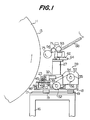
- a drum 11 is provided whose radii from the axis 12 to the outer surface 13 change depending upon axial positions of the surface.
- the radii progressively decrease from the axial center to both the axial ends to form the arcuate outer surface 13 in a sectional plane including a meridian of the drum.
- the drum 11 is rotatively driven about the horizontal axis 12 by means of a motor (not shown).
- An encoder (not shown ) is provided which is adapted to detect rotated amounts of the drum 11.
- a base frame 16 on which are provided a pair of rails 17 extending perpendicularly to the axis of the drum 11.
- a horizontal base plate 18 is provided on its underside with a plurality of slide bearings 19 which are slidably engaged on the rails 17.
- the inner periphery of the guide plate 23 has a center of the curvature positioned at the center of the curvature of the outer surface 13 of the drum 11.
- a traverse frame 27 rotatably carries at its bottom a pair of rollers 28 and 29 arranged spaced from each other by a predetermined distance in the longitudinal direction of the guide plate 23 and rotatable about their vertical axes such that these rollers 28 and 29 are in rotating contact with the outer periphery of the guide plate 23.
- a horizontal arm 30 is arranged on the opposite side of the rollers 28 and 29 with respect to the guide plate 23 and has one end pivotally connected to the traverse frame 27.
- a roller 31 is supported by the horizontal arm 30 substantially at its longitudinal center so as to be rotatable about a vertical axis and in rolling contact with the inner periphery of the guide plate 23.
- a cylinder 32 is rockably supported on the bottom of the traverse frame 27 so as to extend perpendicular to the rotating axis of the drum 11.
- the cylinder 32 includes a piston rod 33 whose outer end is pivotally connected to the other end of the horizontal arm 30.
- the roller 31 is urged against the inner periphery of the guide plate 23 to embrace the guide plate 23 on its inner and outer sides in cooperation with the rollers 28 and 29.
- the vertical axes of these rollers form an imaginary isosceles triangle whose median orthogonally intersect a straight line in parallel with the axis of the drum 11.
- Balls 35 are supported on the bottom of the traverse frame 27 to roll on the upper surface of the base plate 18.
- a pair of bearings 38 spaced in the axial direction of the drum 11 from each other for rotatably supporting both ends of a screw shaft 39 extending in parallel with the axis 12 of the drum 11.
- Slide rails 40 and 41 are arranged on both sides of the screw shaft 39 on the base plate 18 and extend in parallel with the screw shaft 39.
- the screw shaft 39 is threadedly engaged in a movable block 42 to which are fixed slide bearings 43 and 44 slidably engaging the slide rails 40 and 41, respectively.
- a horizontal arcuate chain guide 45 is mounted on blocks 46 fixed on the base plate 18 and arranged below the guide plate 23 immediately in front of the guide plate 23.
- the outer periphery of the chain guide 45 extends along and substantially directly below the inner periphery of the guide plate 23 and has a center of the curvature positioned at the center of the curvature of the outer surface 13 of the drum 11 in the same manner as in the inner periphery of the guide plate 23.
- Receiving bases 47 are arranged on the base plate 18 for rotatably supporting sprockets 48 which are rotated about their vertical axes, respectively.
- An endless chain 49 extend around these sprockets 48, running in sliding contact with the outer periphery of the chain guide 45.
- the movable block 42 is connected to the chain 49 at a point thereon, and the bottom of the traverse frame 27 is connected to the chain 49 at two points thereon spaced equal distances in opposite directions from the point connected to the movable block 42.
- a timing pulley 52 is fixed to one end of the screw shaft 39.
- a timing belt 56 extends around the timing pulley 52 and a timing pulley 55 fixed to the rotating shaft 54 of a motor 53 fixed to the base plate 18.
- An encoder 58 is secured to the other end of the screw shaft 39 to detect rotated amounts of the screw shaft 39, thereby detecting axial positions of the traverse frame 27 and hence the attaching roller later described.
- a pair of guide rails 61 are arranged on the upper surface of the traverse frame 27 to extend in the direction perpendicular to the axis of the drum 11.
- Slide bearings 63 mounted on the underside of a support base 62 slidably engage the guide rails 61.
- the reciprocative motion means is thus constructed from the guide plate 23, the traverse frame 27, the rollers 28, 29 and 31, the arm 30, the cylinder 32, the balls 35, the screw shaft 39, the slide rails 41, the movable block 42, the chain guide 45, the sprockets 48, the endless chain 49 and the motor 53 for reciprocatively moving the support base 62 substantially along the axis 12 of the drum 11, in more exactly along the outer surface 13 of the drum 11 in this case, to maintain the distance between the drum 11 and the support base 62 at a constant value.
- a cylinder 64 is mounted on the upper surface of the traverse frame 27 by means of a bracket 65 to extend in the direction perpendicular to the axis of the drum 11.
- the cylinder 64 includes a piston rod 66 whose rod end is connected to the support base 62.
- a pair of bearings 69 are spaced from each other in the direction perpendicular to the axis of the drum 11 and mounted on the upper surface of the support base 62 for rotatably supporting both the ends of a horizontal shaft 70 also extending in the direction perpendicular to the axis of the drum 11.
- a rocking base 71 is provided with a block 72 into which the horizontal shaft 70 is inserted. On the forward end of the rocking base 71 is mounted a shaft 73 extending at the same level as and in parallel with the axis 12 of the drum 11.
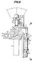
- a pair of bearings 74 are inserted between the shaft 73 and an attaching roller 75 surrounding it (Fig. 8). Consequently, the attaching roller 75 is rotatable about an axis P substantially in parallel with the axis 12 of the drum 11.
- the rocking axis Y of the rocking base 71 or the center axis of the shaft 70 is coincident with the normal K to the outer surface 13 of the drum 11 at the contact point S between the outer surface 13 of the drum 11 and the outer circumferential surface of the attaching roller 75 at the center of its width.
- a pair of vertically extending cylinders 77 and 78 are integrally connected to each other by means of a bracket 79 and arranged on the side of the rocking base 71.
- the cylinder 77 has a piston rod 80 whose rod end is connected to the lower end of the support base 62, while the other cylinder 78 has a piston rod 81 whose rod end is connected to the rocking base 71.
- the rocking base 71 and the attaching roller 75 are rocked about the rocking axis Y through an angle G in the clockwise direction as shown in Fig. 6.
- the cylinders 77 and 78 and the bracket 79 form as a whole the rocking means 82 for rocking the rocking base 71.
- the rocking axis Y of the rocking base 71 is coincident with the normal K passing through the contact point S. Therefore, the contact point S at which the attaching roller 75 contacts the drum 11 will remain unchanged, no matter what directions the rocking base 71 and attaching roller 75 may rock.
- a shaft 85 is vertically extended and rotatably supported on the upper end of the rocking base 71 by means of a pair of bearings 86.
- the upper end of a bracket 87 is secured to the lower end of the shaft 85, while the lower end of the bracket 87 is connected to the forward end of a guide unit 88 extending in the rearward direction by means of a horizontal shaft 92.
- Pairs of guide rollers 89 and 90 spaced vertically from each other are rotatably supported by the guide unit 88.
- a layer L as a narrow belt-shaped member, for example, a rubber coated cord sheet whose cords are arranged parallel to one another is continuously payed out of a winding drum or layer forming device (not shown) which is arranged rearward of the guide unit 88 and fed into the guide unit 88.
- the fed layer is forward supplied through the guide rollers 89 and 90.
- the guide unit 88 is rockable about the shaft 85 in the horizontal directions. Therefore, if the payed-out position of the layer L changes or the support base 62 moves along the outer surface 13 of the drum 11, the guide unit 88 can be directed to the payed-out position of the layer L to ensure that the layer L is reliably guided and supplied.
- a supply roller 93 is rotatably supported by the shaft 92 at the lower end of the bracket 87.
- the supply roller 93 has at the axial ends flanges 94 and is bulged between the flanges to have diameters larger as they are near to the axial center of the roller 93 to form a barrel-shaped roller.
- the layer L After passing through the guide unit 88, the layer L is forwardly supplied by winding partially around the outer peripheral surface 95 of the supply roller 93.
- the layer L is subjected to a centering action to be forwardly fed by the supply roller 93 in a stable condition, inasmuch as its bulged circumferential surface 95.
- a supply roller 96 is rotatably supported by a shaft 97 on the rocking base 71 between the supply roller 93 and the attaching roller 75.
- the axis of the supply roller 96 and hence the shaft 97 is in parallel with the center axis of the shaft 73.
- the layer L which has passed the supply roller 93 is turned into a different direction by winding partially around the outer circumferential surface of the supply roller 96. Thereafter, the layer L is fed to the attaching roller 75.
- the center axis C of the vertical shaft 85 extends through the center of the forward end of the outer peripheral surface 95 of the supply roller 93. Therefore, if the guide unit 88 and the supply roller 93 are rocked, the position of the layer L where it leaves the supply roller 93 remains constant. As a result, the layer L does not deflect from the supply roller 93 in spite of the rocking movement of the guide unit 88 and the supply roller 93.
- the rocking movement of the guide unit 88 is accommodated by the twisting of the layer L between the supply rollers 93 and 96.
- the attaching roller 75 is formed in its outer peripheral surface with a guide groove 99 having a depth less than the thickness t of the layer L and extending in the circumferential direction of the attaching roller 75.
- the layer L fed from the supply roller 96 is guided into the guide groove 99 of the attaching roller 75 and then wound around the circumference of the attaching roller 75 over a predetermined angle. Thereafter, the layer L is fed to the contact point S shown in Fig. 5 by the rotation of the attaching roller 75.
- the layer L is urged at the contact point S to the outer surface of the drum 11 and attached to it by means of the attaching roller 75.
- reference numeral 100 denotes a sequencer which receives detection signals from the encoder at the drum 11 and the encoder 58 and outputs control signals to the motor for the drum 11, the motor 53 and the cylinders 77 and 78.
- the sequencer 100 has memorized various data such as annular positions where the drum 11 should stop and start, extreme positions of reciprocative movements of the support base 62 and the attaching roller 75, rotating speeds and total rotating numbers of the drum 11.
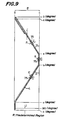
- a layer L is progressively attached to the outer surface 13 of the drum 11 in a zigzag pattern in a range as shown in Fig.
- the degree (d) is 360° plus a predetermined angle J, for example, a value calculated from the width of the layer L and belt angles.
- a predetermined angle J for example, a value calculated from the width of the layer L and belt angles.
- the memorization is effected such that it is rotated at constant high speeds between the angles (d) and (a), between angles (b) and (c) and between the initial zero angle and the angle (a), while at constant low speeds between the angles (a) and (b) and between the angles (c) and (d).
- the drum 11 is rotated at high speeds when the layer L is attached at inclined angles, while the drum 11 is rotated at low speeds when the layer L is attached in the circumferential direction.
- the rotating number of the drum 11 for completely attaching the layer L to the aforementioned region is memorized as a value of one section. In the case that the layer is further attached onto the attached layer L, the laminated number is multiplied by the value and the obtained value is memorized.
- a layer L is wound around the outer surface 13 of the drum 11 in a zigzag pattern in the predetermined region R between the points g and h (Fig. 9)
- the layer L is introduced through the supply rollers 93 and 96 into the guide groove 99 of the attaching roller 75.
- the base plate 18 is then advanced along the guide rails 17 and fixed at the advanced position.
- the cylinder 64 is then actuated to extend its piston rod 66 so that the support base 62, the rocking base 71 and the attaching roller 75 are in unison advanced toward the drum 11, with the result that the layer L on the attaching roller 75 is urged against the drum 11.
- the cylinder 77 is then actuated to extend its piston rod 80 to the full extent so that the rocking base 71 and the attaching roller 75 are rocked about the rocking axis Y through the angle G in the counterclockwise direction viewed in Fig. 6.
- the angle G is substantially equal to an inclined angle H of the layer L to be wound around the drum 11 relative to the circumferential direction of the drum 11.
- a straight line in parallel with the winding direction of the layer L intersects the rotating axis P of the attaching roller 75 at right angles.
- control signals are sent from the sequencer 100 to the motor of the drum 11 and the motor 53 to actuate them, so that the drum 11 is rotated at a predetermined high speed and the screw shaft 39 is rotated.
- the rotation of the screw shaft 39 is converted by means of the movable block 42 into a straight movement which drives the chain 49.
- the traverse frame 27, the support base 62 and the rocking base 71 are moved in unison along the outer surface 13 of the drum 11 from its one axial end to the other axial end, keeping constant the distances from the drum 11. Consequently, the attaching roller 75 is moved from one end to the other end of the region R, that is to say, from the point g to the point h. As a result, the layer L wound partially around the attaching roller 75 is supplied between the attaching roller 75 and the drum 11 so as to be urged against the outer surface 13 of the drum 11 by means of the attaching roller 75.
- the layer L is attached to the outer periphery of the drum 11 at an inclined angle such that the layer L approaches the other axial end of the drum 11 as it advances forward in the rotating direction of the drum 11.
- the supply direction and the winding direction of the layer L are coincident with each other. Consequently, the layer L upon being wound is not subjected to any external force in its width direction from the attaching roller 75 so that the layer L can be wound around the drum 11 in a good condition.
- the drum 11 is then rotated at the high speed and the motor 53 is energized to rotate the screw shaft 39 in the direction opposite to the direction described above.
- the traverse frame 27 and the other members are returned (moved from the other end to the one end of the drum 11) so that the attaching roller 75 is moved from the other end to the one end in the region R or from the point h to the point g, while the attaching roller 75 is rolled on the drum 11.
- the layer 11 is urged against the drum 11 by means of the attaching roller 75 to be attached to the outer circumference of the drum 11 at an inclined angle such that the layer L approaches the one axial end of the drum 11 as it advances forward in the rotating direction of the drum 11.
- the supply direction and the winding direction of the layer L are coincident with each other. Consequently, the layer L upon being wound is not subjected to any external force in its width direction from the attaching roller 75 so that the layer L can be wound around the drum 11 in a good condition.
- the drum 11 When the drum has been rotated through the angle c and the attaching roller 75 has arrived at the point g, the drum 11 is once stopped and the motor 53 is deenergized with control signals from the sequencer 100. The cylinder 78 is then actuated to extend its piston rod 81 to its full extent with a control signal from the sequencer 100. As a result, the attaching roller 75 is rocked until its axis P becomes horizontal. The drum 11 is rotated at the low speed with a control signal from the sequencer 100, while the motor 53 remains in deenergized state so that the layer L is attached to the drum 11 in its circumferential direction, while the attaching roller 75 is in its stopped position.
- the drum 11 When the drum 11 has been rotated through the angle (d), the drum 11 is once stopped and the motor 53 is once deenergized with a control signals from the sequencer 100. Thereafter, the apparatus is returned to the initial state and the operation is again started for attaching a layer L around the drum 11 inclined at the predetermined angle H.
- a layer L is supplied to the drum 11 rotating about its axis 12, while the layer is swung in a constant region R in the axial direction of the drum 11 so that the layer L is wound around the drum in a zigzag pattern.
- the cylinder 64 is actuated to retract its piston rod 66 and the base plate 18 is retracted along the guide rails 17 to its waiting position, whereby moving the support base 62, the rocking base 71 and the attaching roller 75 in unison away from the drum 11.
- drum 11 having the arcuate outer surface 13 is shown onto which a layer L is attached, it will be apparent that the invention is applicable to a drum 11 having a cylindrical outer surface.
- a narrow belt-shaped member can be wound around the drum in a zigzag pattern in a good condition.
Landscapes
- Engineering & Computer Science (AREA)
- Mechanical Engineering (AREA)
- Chemical & Material Sciences (AREA)
- Composite Materials (AREA)
- Robotics (AREA)
- Tyre Moulding (AREA)
Applications Claiming Priority (2)
| Application Number | Priority Date | Filing Date | Title |
|---|---|---|---|
| JP325312/91 | 1991-11-13 | ||
| JP32531291A JP3194765B2 (ja) | 1991-11-13 | 1991-11-13 | 細幅帯状体の巻き付け装置 |
Publications (2)
| Publication Number | Publication Date |
|---|---|
| EP0542431A1 true EP0542431A1 (fr) | 1993-05-19 |
| EP0542431B1 EP0542431B1 (fr) | 1997-01-29 |
Family
ID=18175418
Family Applications (1)
| Application Number | Title | Priority Date | Filing Date |
|---|---|---|---|
| EP92309479A Expired - Lifetime EP0542431B1 (fr) | 1991-11-13 | 1992-10-16 | Dispositif pour enrouler une couche en forme de bande |
Country Status (4)
| Country | Link |
|---|---|
| US (1) | US5395475A (fr) |
| EP (1) | EP0542431B1 (fr) |
| JP (1) | JP3194765B2 (fr) |
| DE (1) | DE69217167T2 (fr) |
Cited By (7)
| Publication number | Priority date | Publication date | Assignee | Title |
|---|---|---|---|---|
| EP1647394A1 (fr) * | 2004-10-14 | 2006-04-19 | Sumitomo Rubber Industries Ltd. | Procédé et dispositif pour la fabrication d'un objet par enroulement d'une bandelette en caoutchouc sur un support |
| EP1785263A1 (fr) * | 2005-11-15 | 2007-05-16 | Sumtiomo Rubber Industries Ltd | Dispositif pour appliquer une bande caoutchoutée |
| EP1967389A1 (fr) * | 2007-03-08 | 2008-09-10 | Continental Aktiengesellschaft | Pneu de véhicule et procédé de fabrication d'un ensemble de nappes d'armature d'un pneu de véhicule |
| EP1815971A4 (fr) * | 2004-10-21 | 2008-12-17 | Bridgestone Corp | Dispositif et procede pour element d' estampage en forme de bande |
| EP2050560A1 (fr) * | 2007-10-18 | 2009-04-22 | Continental Aktiengesellschaft | Dispositif d'application de bandes de matériau sur un pneu cru ou un tambour de fabrication |
| EP2253443A1 (fr) * | 2009-05-19 | 2010-11-24 | Continental Reifen Deutschland GmbH | Procédé de fabrication d'un pneu de véhicule |
| CN101209594B (zh) * | 2006-12-27 | 2011-05-25 | 天津市橡塑机械研究所有限公司 | 轮胎胎面缠绕机组 |
Families Citing this family (24)
| Publication number | Priority date | Publication date | Assignee | Title |
|---|---|---|---|---|
| EP1446280B1 (fr) * | 2001-10-25 | 2005-12-28 | PIRELLI PNEUMATICI Società per Azioni | Procede de production d'elements de renforcement pour pneus de vehicule et pneus obtenus par le biais dudit procede |
| AU2002222530A1 (en) * | 2001-11-22 | 2003-06-10 | Pirelli Pneumatici S.P.A. | Method for making reinforcing structures for vehicles tyres and a tyre obtained thereby |
| EP1541326A4 (fr) * | 2002-07-25 | 2006-04-12 | Bridgestone Corp | Dispositif de fixation de composant de pneumatique |
| KR100553892B1 (ko) * | 2003-10-13 | 2006-02-24 | 삼성전자주식회사 | 디지털 영상 보간 방법 및 장치 |
| EP1533107B1 (fr) * | 2003-11-21 | 2007-01-03 | Société de Technologie Michelin | Appareil et procédé de pose d'une bandelette en continu sur une surface toroidale |
| EP1710188B1 (fr) | 2004-01-28 | 2010-11-24 | Toray Industries, Inc. | Guide de voie du fil, dispositif de va-et-vient d'un faiseau de fibres et dispositif de production de rouleaux de faiseaux de fibres |
| JP4673614B2 (ja) * | 2004-12-02 | 2011-04-20 | 住友ゴム工業株式会社 | タイヤ用ゴム部材の製造方法 |
| JP2006110856A (ja) * | 2004-10-14 | 2006-04-27 | Sumitomo Rubber Ind Ltd | ゴムストリップの貼付装置 |
| JP2007030299A (ja) * | 2005-07-26 | 2007-02-08 | Bridgestone Corp | ピッチ送りローラによるワイヤ配列方法 |
| EP2058114B1 (fr) * | 2006-08-28 | 2012-04-18 | Toyo Tire & Rubber Co. Ltd. | Procédé de fabrication d'un pneu |
| US7957083B2 (en) | 2007-07-23 | 2011-06-07 | Hitachi Global Storage Technologies Netherlands B.V. | Method for early detection of magnetic head degradation due to carbon overcoat wear |
| CN101574853B (zh) * | 2008-05-05 | 2011-07-20 | 天津赛象科技股份有限公司 | 一种特巨型全钢工程子午线轮胎三维缠贴机构 |
| JP4922425B2 (ja) * | 2010-03-19 | 2012-04-25 | 住友ゴム工業株式会社 | ゴムストリップの押付け装置 |
| IT1399702B1 (it) * | 2010-04-26 | 2013-04-26 | Marangoni Meccanica | Metodo e gruppo per la rullatura di uno pneumatico |
| JP5767623B2 (ja) | 2012-12-27 | 2015-08-19 | 住友ゴム工業株式会社 | ゴムストリップの貼付装置 |
| US10307980B2 (en) * | 2013-02-20 | 2019-06-04 | The Goodyear Tire & Rubber Company | Tire building applicator members and systems |
| US20150041067A1 (en) * | 2013-08-07 | 2015-02-12 | The Goodyear Tire & Rubber Company | Component applying/cutting apparatus for a tire building machine |
| JP5797730B2 (ja) | 2013-12-24 | 2015-10-21 | 株式会社ブリヂストン | 帯状部材の巻付け装置 |
| JP5945290B2 (ja) * | 2014-02-24 | 2016-07-05 | 住友ゴム工業株式会社 | タイヤ部材形成装置 |
| JP2015199213A (ja) * | 2014-04-04 | 2015-11-12 | 株式会社ブリヂストン | 帯状部材の巻付け方法および装置 |
| JP6506612B2 (ja) * | 2015-05-11 | 2019-04-24 | 住友ゴム工業株式会社 | モーターサイクル用タイヤ及びモーターサイクル用タイヤの製造方法 |
| US10717225B2 (en) * | 2017-09-07 | 2020-07-21 | The Boeing Company | Drape forming end effector |
| US11040512B2 (en) * | 2017-11-08 | 2021-06-22 | Northrop Grumman Systems Corporation | Composite structures, forming apparatuses and related systems and methods |
| CN116749550B (zh) * | 2023-08-23 | 2023-11-03 | 太原理工大学 | 一种用于回转体构件的纤维自动铺放装置和控制方法 |
Citations (7)
| Publication number | Priority date | Publication date | Assignee | Title |
|---|---|---|---|---|
| US3223572A (en) * | 1959-12-24 | 1965-12-14 | American Mach & Foundry | Machine for building a tread on pneumatic tires |
| US4461669A (en) * | 1983-09-30 | 1984-07-24 | The Boeing Company | Pivotal mount for laminating head |
| US4775433A (en) * | 1985-08-28 | 1988-10-04 | Bridgestone Corporation | Method and apparatus for manufacturing ring-shaped bodies |
| US4822444A (en) * | 1986-04-25 | 1989-04-18 | Rohr Industries, Inc. | Filament winding mechanism for forming and winding a shingled gap free band |
| LU87565A1 (fr) * | 1988-07-28 | 1989-10-26 | Goodyear Tire & Rubber | Procede et appareil d'application de spires pour fabrication d'une bande de roulement |
| US4909880A (en) * | 1988-05-17 | 1990-03-20 | General Dynamics Corporation | Method and apparatus for tape winding on irregular shapes |
| EP0453220A2 (fr) * | 1990-04-20 | 1991-10-23 | Bridgestone Corporation | Dispositif de bobinage de cordages |
Family Cites Families (5)
| Publication number | Priority date | Publication date | Assignee | Title |
|---|---|---|---|---|
| US3721599A (en) | 1968-05-20 | 1973-03-20 | Deering Milliken Res Corp | Method and apparatus for securing a continuous thread on a support surface |
| US3729365A (en) * | 1970-09-03 | 1973-04-24 | Deering Milliken Res Corp | Endless reinforcement and method for producing same |
| FR2579130B1 (fr) * | 1985-03-25 | 1987-10-09 | Aerospatiale | Procede et dispositif pour realiser une piece creuse de forme complexe par enroulement filamentaire au contact |
| JPH04331603A (ja) * | 1990-06-21 | 1992-11-19 | Sumitomo Rubber Ind Ltd | 自動二輪車用バイアスタイヤ |
| JP2628939B2 (ja) * | 1991-02-28 | 1997-07-09 | 住友ゴム工業株式会社 | 空気入りタイヤ |
-
1991
- 1991-11-13 JP JP32531291A patent/JP3194765B2/ja not_active Expired - Lifetime
-
1992
- 1992-10-16 EP EP92309479A patent/EP0542431B1/fr not_active Expired - Lifetime
- 1992-10-16 DE DE69217167T patent/DE69217167T2/de not_active Expired - Lifetime
- 1992-10-20 US US07/963,683 patent/US5395475A/en not_active Expired - Lifetime
Patent Citations (7)
| Publication number | Priority date | Publication date | Assignee | Title |
|---|---|---|---|---|
| US3223572A (en) * | 1959-12-24 | 1965-12-14 | American Mach & Foundry | Machine for building a tread on pneumatic tires |
| US4461669A (en) * | 1983-09-30 | 1984-07-24 | The Boeing Company | Pivotal mount for laminating head |
| US4775433A (en) * | 1985-08-28 | 1988-10-04 | Bridgestone Corporation | Method and apparatus for manufacturing ring-shaped bodies |
| US4822444A (en) * | 1986-04-25 | 1989-04-18 | Rohr Industries, Inc. | Filament winding mechanism for forming and winding a shingled gap free band |
| US4909880A (en) * | 1988-05-17 | 1990-03-20 | General Dynamics Corporation | Method and apparatus for tape winding on irregular shapes |
| LU87565A1 (fr) * | 1988-07-28 | 1989-10-26 | Goodyear Tire & Rubber | Procede et appareil d'application de spires pour fabrication d'une bande de roulement |
| EP0453220A2 (fr) * | 1990-04-20 | 1991-10-23 | Bridgestone Corporation | Dispositif de bobinage de cordages |
Cited By (10)
| Publication number | Priority date | Publication date | Assignee | Title |
|---|---|---|---|---|
| EP1647394A1 (fr) * | 2004-10-14 | 2006-04-19 | Sumitomo Rubber Industries Ltd. | Procédé et dispositif pour la fabrication d'un objet par enroulement d'une bandelette en caoutchouc sur un support |
| US7510616B2 (en) | 2004-10-14 | 2009-03-31 | Sunitomo Rubber Industries, Ltd. | Producing method of rubber strip winding body, and rubber strip winding apparatus |
| EP1815971A4 (fr) * | 2004-10-21 | 2008-12-17 | Bridgestone Corp | Dispositif et procede pour element d' estampage en forme de bande |
| US7947140B2 (en) | 2004-10-21 | 2011-05-24 | Bridgestone Corporation | Strip member application system and method |
| EP1785263A1 (fr) * | 2005-11-15 | 2007-05-16 | Sumtiomo Rubber Industries Ltd | Dispositif pour appliquer une bande caoutchoutée |
| CN1966252B (zh) * | 2005-11-15 | 2012-08-29 | 住友橡胶工业株式会社 | 施加橡胶带的装置 |
| CN101209594B (zh) * | 2006-12-27 | 2011-05-25 | 天津市橡塑机械研究所有限公司 | 轮胎胎面缠绕机组 |
| EP1967389A1 (fr) * | 2007-03-08 | 2008-09-10 | Continental Aktiengesellschaft | Pneu de véhicule et procédé de fabrication d'un ensemble de nappes d'armature d'un pneu de véhicule |
| EP2050560A1 (fr) * | 2007-10-18 | 2009-04-22 | Continental Aktiengesellschaft | Dispositif d'application de bandes de matériau sur un pneu cru ou un tambour de fabrication |
| EP2253443A1 (fr) * | 2009-05-19 | 2010-11-24 | Continental Reifen Deutschland GmbH | Procédé de fabrication d'un pneu de véhicule |
Also Published As
| Publication number | Publication date |
|---|---|
| DE69217167D1 (de) | 1997-03-13 |
| EP0542431B1 (fr) | 1997-01-29 |
| JPH05131565A (ja) | 1993-05-28 |
| US5395475A (en) | 1995-03-07 |
| DE69217167T2 (de) | 1997-07-03 |
| JP3194765B2 (ja) | 2001-08-06 |
Similar Documents
| Publication | Publication Date | Title |
|---|---|---|
| EP0542431B1 (fr) | Dispositif pour enrouler une couche en forme de bande | |
| US4150801A (en) | Automatic winding machine for wire-like object | |
| US5169483A (en) | Tire component member attaching apparatus | |
| CA2005148C (fr) | Methode et appareil de depliage d'elements de pneus | |
| EP1785263A1 (fr) | Dispositif pour appliquer une bande caoutchoutée | |
| AU675489B2 (en) | A control system for a machine for winding electrical cablesand the like, and a method of controlling the machine | |
| JPH0777766B2 (ja) | タイヤ構成部材の巻付け方法および装置 | |
| KR970025931A (ko) | 타이어 제조 방법 및 장치 | |
| RU2127191C1 (ru) | Устройство для автоматического накладывания бесконечной полосы прорезиненной текстильной ткани на барабан для сборки шин | |
| EP1595838B1 (fr) | Procede et dispositif de stockage temporaire d'un corps lineaire | |
| US4775433A (en) | Method and apparatus for manufacturing ring-shaped bodies | |
| US5335415A (en) | Apparatus for winding and pressure-fitting a small width strip to a rotating body | |
| US4877477A (en) | Strip supplying device | |
| MX2010011039A (es) | Metodo y aparato para producir neumaticos verdes. | |
| US6173918B1 (en) | Veneer reeling apparatus | |
| EP0421803A1 (fr) | Procédé et installation d'enduction d'une nappe de fils de chaîne | |
| JP3020993B2 (ja) | コードの巻付け装置 | |
| JPH0348024B2 (fr) | ||
| US5273268A (en) | Sheet member grasping device for supply apparatus | |
| CA2004873C (fr) | Methode et dispositif d'enroulement de courroies | |
| JPH06286022A (ja) | ビードコア形成装置 | |
| KR20030022982A (ko) | 권취기의 강판 유도장치 | |
| CN212268961U (zh) | 一种高速复卷机 | |
| USRE28043E (en) | Method of building a tire casing from a strip op rubber | |
| JP3238273B2 (ja) | 光ファイバ巻取り機とその回転数制御方法 |
Legal Events
| Date | Code | Title | Description |
|---|---|---|---|
| PUAI | Public reference made under article 153(3) epc to a published international application that has entered the european phase |
Free format text: ORIGINAL CODE: 0009012 |
|
| AK | Designated contracting states |
Kind code of ref document: A1 Designated state(s): DE ES FR GB IT |
|
| 17P | Request for examination filed |
Effective date: 19930712 |
|
| 17Q | First examination report despatched |
Effective date: 19941104 |
|
| GRAG | Despatch of communication of intention to grant |
Free format text: ORIGINAL CODE: EPIDOS AGRA |
|
| GRAH | Despatch of communication of intention to grant a patent |
Free format text: ORIGINAL CODE: EPIDOS IGRA |
|
| RBV | Designated contracting states (corrected) |
Designated state(s): DE FR IT |
|
| GRAH | Despatch of communication of intention to grant a patent |
Free format text: ORIGINAL CODE: EPIDOS IGRA |
|
| GRAA | (expected) grant |
Free format text: ORIGINAL CODE: 0009210 |
|
| AK | Designated contracting states |
Kind code of ref document: B1 Designated state(s): DE FR IT |
|
| REF | Corresponds to: |
Ref document number: 69217167 Country of ref document: DE Date of ref document: 19970313 |
|
| ITF | It: translation for a ep patent filed | ||
| ET | Fr: translation filed | ||
| PLBE | No opposition filed within time limit |
Free format text: ORIGINAL CODE: 0009261 |
|
| 26N | No opposition filed | ||
| PGFP | Annual fee paid to national office [announced via postgrant information from national office to epo] |
Ref country code: DE Payment date: 20101013 Year of fee payment: 19 |
|
| PGFP | Annual fee paid to national office [announced via postgrant information from national office to epo] |
Ref country code: IT Payment date: 20101020 Year of fee payment: 19 |
|
| PGFP | Annual fee paid to national office [announced via postgrant information from national office to epo] |
Ref country code: FR Payment date: 20111103 Year of fee payment: 20 |
|
| REG | Reference to a national code |
Ref country code: DE Ref legal event code: R071 Ref document number: 69217167 Country of ref document: DE |
|
| REG | Reference to a national code |
Ref country code: DE Ref legal event code: R071 Ref document number: 69217167 Country of ref document: DE |