EP0543191B1 - Appareil et méthode d'entrée de données de patients - Google Patents
Appareil et méthode d'entrée de données de patients Download PDFInfo
- Publication number
- EP0543191B1 EP0543191B1 EP92118589A EP92118589A EP0543191B1 EP 0543191 B1 EP0543191 B1 EP 0543191B1 EP 92118589 A EP92118589 A EP 92118589A EP 92118589 A EP92118589 A EP 92118589A EP 0543191 B1 EP0543191 B1 EP 0543191B1
- Authority
- EP
- European Patent Office
- Prior art keywords
- film
- information
- card
- assembly
- scanned
- Prior art date
- Legal status (The legal status is an assumption and is not a legal conclusion. Google has not performed a legal analysis and makes no representation as to the accuracy of the status listed.)
- Expired - Lifetime
Links
- 238000000034 method Methods 0.000 title claims description 16
- 238000003384 imaging method Methods 0.000 claims description 39
- 238000012545 processing Methods 0.000 claims description 14
- 230000007246 mechanism Effects 0.000 claims description 10
- 238000004519 manufacturing process Methods 0.000 claims description 5
- 238000013519 translation Methods 0.000 claims description 4
- 230000007723 transport mechanism Effects 0.000 claims description 3
- 238000003860 storage Methods 0.000 description 9
- 230000032258 transport Effects 0.000 description 6
- 238000003491 array Methods 0.000 description 5
- 238000003780 insertion Methods 0.000 description 5
- 230000037431 insertion Effects 0.000 description 5
- 230000005855 radiation Effects 0.000 description 4
- 125000006850 spacer group Chemical group 0.000 description 4
- 238000012937 correction Methods 0.000 description 3
- 230000003287 optical effect Effects 0.000 description 3
- 239000000853 adhesive Substances 0.000 description 2
- 230000001070 adhesive effect Effects 0.000 description 2
- 238000010586 diagram Methods 0.000 description 2
- 238000005286 illumination Methods 0.000 description 2
- 238000003825 pressing Methods 0.000 description 2
- 230000003068 static effect Effects 0.000 description 2
- 230000000903 blocking effect Effects 0.000 description 1
- 238000004364 calculation method Methods 0.000 description 1
- 238000004891 communication Methods 0.000 description 1
- 238000011161 development Methods 0.000 description 1
- 239000000428 dust Substances 0.000 description 1
- 239000011796 hollow space material Substances 0.000 description 1
- 238000012432 intermediate storage Methods 0.000 description 1
- 238000013507 mapping Methods 0.000 description 1
- 238000005259 measurement Methods 0.000 description 1
- 230000000284 resting effect Effects 0.000 description 1
Images



Classifications
-
- G—PHYSICS
- G03—PHOTOGRAPHY; CINEMATOGRAPHY; ANALOGOUS TECHNIQUES USING WAVES OTHER THAN OPTICAL WAVES; ELECTROGRAPHY; HOLOGRAPHY
- G03B—APPARATUS OR ARRANGEMENTS FOR TAKING PHOTOGRAPHS OR FOR PROJECTING OR VIEWING THEM; APPARATUS OR ARRANGEMENTS EMPLOYING ANALOGOUS TECHNIQUES USING WAVES OTHER THAN OPTICAL WAVES; ACCESSORIES THEREFOR
- G03B42/00—Obtaining records using waves other than optical waves; Visualisation of such records by using optical means
- G03B42/02—Obtaining records using waves other than optical waves; Visualisation of such records by using optical means using X-rays
- G03B42/04—Holders for X-ray films
- G03B42/047—Holders for X-ray films provided with marking means
-
- G—PHYSICS
- G03—PHOTOGRAPHY; CINEMATOGRAPHY; ANALOGOUS TECHNIQUES USING WAVES OTHER THAN OPTICAL WAVES; ELECTROGRAPHY; HOLOGRAPHY
- G03B—APPARATUS OR ARRANGEMENTS FOR TAKING PHOTOGRAPHS OR FOR PROJECTING OR VIEWING THEM; APPARATUS OR ARRANGEMENTS EMPLOYING ANALOGOUS TECHNIQUES USING WAVES OTHER THAN OPTICAL WAVES; ACCESSORIES THEREFOR
- G03B42/00—Obtaining records using waves other than optical waves; Visualisation of such records by using optical means
- G03B42/02—Obtaining records using waves other than optical waves; Visualisation of such records by using optical means using X-rays
- G03B42/04—Holders for X-ray films
- G03B42/045—Holders for X-ray films apparatus for loading or unloading the holders
Definitions
- This invention relates to an apparatus and process for scanning input information from patient information cards, processing the information and imaging the processed information on films and, in particular, on X-ray films in automatic daylight film handling systems.
- film sheets and in particular X-ray film sheets, were handled manually by loading the film sheet into a cassette in the dark, exposing it under daylight conditions and then taking the cassette into a darkroom, opening it and placing the film sheet into a processor all in the dark.
- One prior art automatic film handling system includes a direct imaging camera within the system itself.
- Patient information is printed on a card.
- the card is flash illuminated.
- the reflected image is directed by lenses, prisms and mirrors directly onto a previously unexposed area of the film prior to processing.
- Other information such as time and date, can be added by reflecting a light beam onto a representation of the time and date.
- the light reflected from the representation of the time and date is combined with the light reflected from the card such that both the card information and the other information is reflected onto the previously unexposed area of the film prior to development of the film.
- the precharacterizing part of new claim 1 starts from Patent Abstracts of Japan JP-1 072 133 which describes a device for imprinting identification information on an X-ray film.
- This device comprises a scanner apparatus for scanning input information, an electronic control system connected to the scanner apparatus and capable of processing the scanned input information to output information and a camera apparatus connected to the electronic control system for imaging the output information onto the X-ray film.
- the device only allows for the information being imprinted in a standard position under standard conditions. The device does not allow for the patient information being processed to be imaged at a desirable place such that the imaged information is right reading.
- one prior art automatic film handling system with a direct imaging camera within the system itself includes two distinct card holding mechanisms for receiving a patient identification card. One of the mechanisms is accessible from one side of the system and the other mechanism is accessible from another side of the system.
- the patient information card is inserted in the first mechanism if the radiograph was taken with the patient facing towards the X-ray source.
- the patient information card is inserted in the other one of the mechanisms if the radiograph was taken with the patient facing away from the X-ray source.
- This prior art system has a distinct illumination source and a different set of optics for reflecting and directing an image from a card in each one of the two card holding mechanisms to the film to be imaged.
- All prior art automatic X-ray film handling systems which include a direct imaging camera within the system itself only produce a negative image (i.e., white characters on a black background) of patient information on the film.
- a negative image i.e., white characters on a black background
- Light is absorbed by black and reflected by white.
- Patient ID cards are black typing on white background.
- light directed towards the patient ID card by prior art direct image cameras is reflected off the white backgrounds of the cards and absorbed by the black typing on the cards.
- Light imaged on X-ray film makes it black.
- the reflected light from the white background of the card is what exposes the X-ray film producing a black field with clear letters on the radiograph.
- a positive image i.e., black characters on a white background
- prior art automatic X-ray film handling systems can not produce a positive image of the patient information on the film.
- No prior art automatic X-ray film handling system which includes a direct imaging camera within the system is capable of adding information to the reflected images or providing the operator with options to change the size, font and/or format of such information. It is the object of the present invention to propose flexible apparatus and a process for placing patient identification on films and, in particular, on X-ray films in automatic daylight film handling systems. This object is solved according to the invention with the features of claims 1, 7 and 8, respectively.
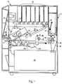
- Figure 1 is a simplified schematic cross sectional view of an automatic daylight film handling apparatus including a schematic representation of an electronic patient information imaging assembly in accordance with the present invention.
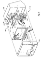
- Figure 2 is a perspective view of the electronic patient information imaging assembly with parts exploded from one another including a scanner apparatus, a camera apparatus and an electronic control system.
- Figure 3 is an enlarged perspective view of the scanner apparatus with parts exploded from one another including a universal card holder, a translation mechanism, a light source, a first lens assembly and a sensor assembly.
- Figure 4 is a schematic illustration showing a plurality of patient information cards and how they insert in the universal card holder.
- Figure 5 is a perspective view of the universal card holder as seen by an operator.
- Figure 5a is an enlarged perspective view of the universal card holder as seen by an operator.
- Figure 6 is an enlarged partially exploded view of the camera apparatus including a cathode ray tube assembly, a second lens assembly and a reflector.
- Figure 7 is an enlarged partially exploded view of the second lens assembly and the reflector.
- Figure 8 is a cross sectional view of the second lens assembly.
- Figure 9 is a functional block diagram showing the flow of signals generated by the sensor assembly of the scanner apparatus through the electronic control system to the CRT assembly.
- Figure 10a schematically illustrates a process for preparing a radiograph where a patient is facing an X-ray source in an exposure step in accordance with the present invention.
- Figure 10b schematically illustrates a process for preparing a radiograph where a patient is facing away from an X-ray source in an exposure step in accordance with the present invention.
- Figure 10c schematically illustrates a process for preparing a radiograph where patient information is imaged onto a bottom half of a previously unexposed area of an X-ray film in accordance with the present invention.
- an automatic daylight film handling apparatus 10 is shown with an electronic patient information imaging assembly 100 of the present invention.
- the electronic patient information imaging assembly 100 comprises a scanner apparatus 102, a camera apparatus 104 and an electronic control system 106.
- the operation of the automatic film handling apparatus 10 begins by an operator inserting a closed cassette having an exposed film into an entrance slot 14 in a substantially light tight housing adjacent a feed tray 16 of the film handling apparatus 10.
- the slot 14 has a light gate (not depicted) which opens and closes to allow the cassette into the light tight housing of the apparatus 10 and yet prevents light from entering into an interior of the apparatus 10.
- a pair of nip rollers 18 inside the entrance slot 14 initially transports the cassette from the feed tray 16.
- a plurality of rollers 20 transports the cassette further into a cassette opening-closing assembly 22.
- the pair of nip rollers 18 and the plurality of rollers 20 comprise an initial transport mechanism for transporting the closed cassette to an initial station within the apparatus 10.
- the cassette is aligned to a front corner of the opening-closing assembly 22.
- the opening-closing assembly 22 opens the cassette by disengaging latches on the cassette and lifting a door of the cassette.
- Exposed film in the opened cassette 24 is removed from the cassette 24 by a vacuum-operated lifting and transporting assembly 26 which lifts and transports the exposed film to a patient identification station adjacent the camera apparatus 104.
- a card with patient identification information and other data written, printed or typed on it corresponding to the patient whose radiograph is adjacent the camera apparatus 104 is inserted in the scanner apparatus 102.
- the scanner apparatus 102 scans the information and other data from the card.
- the electronic control system 106 receives electronic signals representative of the patient identification information and other data from the scanner apparatus 102.
- the electronic control system 106 digitizes the information and other data, potentially modifies the information and other data and drives the camera apparatus 104 to image the patient information, other data and possibly additional information or data on a previously unexposed area of the film.
- the vacuum-operated lifting and transporting assembly 26 transports the film to a first roller 51 and a second roller 52 of a film or sheet diverting apparatus 30.
- the vacuum-operated lifting assembly 26, for example, can be as disclosed in EP-B-0 467 203 and the film or sheet diverting apparatus 30 can be as disclosed in EP-A-0 543 193 concurrently filed herewith and assigned to the assignee of the present invention.
- the automatic daylight film handling apparatus 10 includes film reloading apparatus for reloading the cassette with non-exposed film.
- the operator may input at a console 32 associated with the film handling apparatus 10 the type of film desired for the re-loading of the cassette 24.
- a microcomputer (not depicted) associated with the apparatus 10 can determine the type of film needed from a sensor (not depicted) reading a label on the cassette 24.
- An appropriate fresh, i.e., non-exposed, film is dispensed from one of a plurality of film storage magazines 34 through a dispensing slot 31 onto a first endless belt 33 which is driven by a roller 35.
- a suitable film storage magazine 34 that can be used as stated herein, see U.S.
- Patent 4,482,146 The first belt 33 is moving clockwise in Figure 1 when a fresh film is dispensed so that a leading edge of the fresh film is directed to a nip formed between a top surface or run of the first belt 33 and a roller 37 substantially below the film storage magazine 34 and beside the dispensing slot 31. Since each roller 37 associated with a film storage magazine 34 forms a nip between itself and the top run of the first belt 33, the fresh film is transported on the first belt 33 to a nip formed between the first belt 33 and a second endless belt 39.
- the second belt 39 is driven by frictional contact with the first belt 33 and is moving counter-clockwise in Figure 1.
- each of the first endless belt and the second endless belt can include one or more belts.
- the fresh film travels down the chute 36 to a pair of nip rollers 38 which hold the fresh film and extend in the direction of arrow A in Figure 1 to place the fresh film into the opened cassette 24.
- the opening-closing assembly 22 closes the cassette 24 and secures the latches on the cassette 24.
- the plurality of rollers 20 transports the cassette 24 from the opening-closing assembly 22 and eject the cassette onto the feed tray 16.
- a sensor detects the presence of the exposed film at a nip between the first roller 51 and the second roller 52 of the sheet diverting apparatus 30 and sends the film presence information to the microcomputer.
- the microcomputer also receives information from a second sensor (not shown) on the presence of another film in a feed tray 40 of a processor 42 associated with the film handling apparatus 10.
- the microcomputer determines whether the film can be transported directly into the processor 42 or should be transported into an intermediate film storage apparatus 12 associated with the film handling apparatus 10 for dispensing at a later time, and directs the movement of the sheet diverting apparatus 30 to thereby guide the exposed film to the appropriate path accordingly.
- the film is transported vertically or substantially vertically by the first roller 51 and a third roller 53 of the diverting apparatus 30 into the entrance 46 of the intermediate storage apparatus 12 and to a nip between a pair of rollers 47, such as, within the storage apparatus 12.
- a suitable intermediate film storage apparatus 12 that can be used as stated herein, see EP-A-0 543 192.
- Figure 2 is a perspective view of the electronic patient information imaging assembly 100 with parts exploded from one another.
- the parts of the electronic patient information imaging assembly 100 include the scanner apparatus 102, the camera apparatus 104 and the electronic control system 106.
- FIG 3 is an enlarged perspective view of the scanner apparatus 102 with parts exploded from one another.
- the scanner apparatus 102 includes a universal card holder 108, a translation mechanism 110, a light source 112, a first lens assembly 114 and a sensor assembly 116.
- the universal card holder 108 comprises a card window frame 118 mounted to a card holder 120 defining a slot 122 between the card holder 108 and the card window frame 118 for inserting cards.
- Spring members 124 are in the slot 122 and connected in recesses to the card window frame 118 to hold the inserted card in place against the card holder 120.
- the spring members 124 are connected in recesses to the card holder 120 to hold the inserted card against the card window frame 118.
- the card holder 120 has a passage 126 through which a sensor 128 can sense the presence of a card.
- the card window frame 118 defines a window 130 through which an image to be scanned on an inserted card can be viewed by an operator and scanned by the sensor assembly 116.
- the card holder 120 further has a first abutment surface 131, a second abutment surface 132, a third abutment surface 133, a fourth abutment surface 134, a fifth abutment surface 135, a sixth abutment surface 136, and a seventh abutment surface 137 for contacting edges of different cards inserted into the universal card holder 108.
- the first 131 and second 132 abutment surfaces are parallel to one another and spaced a first distance d 1 from one another.
- the third 133 and fourth 134 abutment surfaces are parallel to one another, parallel to the first 131 and second 132 abutment surfaces, and spaced a second distance d 2 from one another where the second distance d 2 is less than the first distance d 1 .
- the fifth abutment surface 135 is perpendicular to the first through fourth abutment surfaces 131-134 and connects first ends of the third 133 and fourth 134 abutment surfaces.
- the sixth abutment surface 136 is perpendicular to the first through fourth abutment surfaces 131-134 and interconnects an inner end of the first abutment surface 131 and a second end of the third abutment surface 133.
- the seventh abutment surface 137 is perpendicular to the first through fourth abutment surfaces 131-134 and interconnects an inner end of the second abutment surface 132 and a second end of the fourth abutment surface 134.
- the sixth 136 and seventh 137 abutment surfaces are coplanar.
- Joints between connecting abutment surfaces can be curved, right angled, other angled or other shaped.
- the purpose of the first through seventh abutment surfaces 131-137 is to contact edges of different existing standard size patient identification cards thereby aligning and registering the cards within the universal card holder 108 such that areas to be scanned on the cards are positioned under the window 130 when the card is fully inserted in the universal card holder 108 and the card is abutting against an appropriate one or more of the abutment surfaces 131-137.
- FIG. 4 shows a plurality of patient information cards 141-144 and how they insert in the slot 122 of the universal card holder 108.
- the patient information card 141 illustrates the standard Du Pont DayLightTM patient ID card. This card 141 is about 120 millimeters (mm) long by 76 mm wide. This card 141 is properly positioned in the slot 122 of the universal card holder 108 when a first end edge 146 of the card 141 is in contact with the fifth abutment surface 135.
- a first side edge 147 of the card 141 may also be in contact with the third abutment surface 133 and/or a second side edge 148 of the card 141 may also be in contact with the fourth abutment surface 134.
- a scanning area 149 running entirely across a middle section of the card 141 is appropriately aligned under the window 130 so information or data on the scanning area 149 can be scanned by the sensor assembly 116.
- the patient information card 142 illustrates the standard IBM style patient ID punch card.
- This card 142 is about 82 mm long by 187 mm wide.
- This card 142 is properly positioned in the slot 122 of the universal card holder 108 when a first end edge 150 of the card 142 is in contact with the seventh abutment surface 137 and a right side edge 152 of the card 142 is in contact with the second abutment surface 132.
- a scanning area 154 located generally on an upper left corner of the card 142 is appropriately aligned under the window 130 so information or data on the scanning area 154 can be scanned by the sensor assembly 116.
- the patient information card 143 illustrates the standard 3 inch by 5 inch (about 76 mm long by 127 mm wide) Eastman Kodak dark room patient ID card.
- This card 143 is properly positioned in the slot 122 of the universal card holder 108 when a first end edge 156 of the card 143 is in contact with the sixth and seventh abutment surfaces 136,137 and a left side edge 158 of the card 143 is in contact with the first abutment surface 131.
- a scanning area 160 located generally on a middle section adjacent the first end edge 156 of the card 142 is appropriately aligned under the window 130 so information or data on the scanning area 160 can be scanned by the sensor assembly 116.
- the patient information card 144 illustrates other standard size cards similar to the Eastman Kodak dark room patient ID card that register in the universal card holder 108 similar to the Eastman Kodak dark room patient ID card 143, but are not 3 inch by 5 inch cards.
- the card 144 may be 2 inches by 6 inches or other measurements.
- the translation mechanism 110 comprises a linear ball slide 162 with an outer slide part 164 and an inner slide part 166.
- the outer slide part 164 is mounted to the card holder 120.
- the inner slide part 166 is mounted to a first bracket 168 which in turn is mounted to a scanner frame 170 which in turn is mounted to a front door panel 172. See Figure 1.
- a gear rack 174 is fixed to the outer slide part 164.
- the stepper motor assembly 176 is mounted on a second bracket 178 which in turn is connected to the scanner frame 170.
- the stepper motor assembly 176 is electrically connected to the electronic control system 106 such that when instructed to do so the stepper motor assembly 176 linearly moves the universal card holder 108 one step at a time across a scan line of the sensor assembly 116 allowing the scanning areas of the cards to be incrementally scanned one line at a time by the sensor assembly 116 as the scanning area moves under it step by step of the motor assembly 176.
- a sensor 177 is mounted to the scanner frame 170 and is electrically connected to the electronic control system 106.
- the sensor 177 can be a photoreflective sensor or limit switch which generates a signal when the universal card holder 108 is in its fully outward extended or home position.
- the sensor 128 is also mounted on the bracket 168 and is electrically connected to the electronic control system 106.
- the sensor 128 can be a photoreflective sensor or limit switch used to detect and send signals representative of the presence or absence of a card in the universal card holder 108 by sensing through the hole 126.
- the scanner frame 170 and the front door panel 172 have openings in them for receiving the universal card holder 108 such that an operator has access to the slot 122 and visible access to the window 130 when the universal card holder 108 is in its fully outward extended or home position.
- Figure 5 illustrates the front door panel 172 as seen by on operator.
- Figure 5a is an enlarged perspective view the universal card holder 108 as seen by an operator.
- the front door panel 172 has a viewing recess 190 therein to allow the operator to view the area to be scanned through the window 130 when the universal card holder 108 is in its fully outward extended or home position.
- An operator interface 192 which is electrically interconnected to the electronic control system 106 can be mounted on the front door panel 172.
- the operator interface 192 can have a viewing display and input keys.
- a stationary card holder 194 can be provided on the front door panel for holding cards that either already have been scanned or are to be scanned by the scanner apparatus 102.
- the stationary card holder 194 can be a slot with spring members mounted in the slot similar to the spring members 124 positioned in the slot 122 for biasing the cards against the front door panel 172.
- a manual scan control button 196 and an AP/PA toggle switch 198 can be mounted on the front door panel 196 and electrically interconnected to the electronic control system 106. Pressing the manual scan control button 196 causes the scanner apparatus 102 to scan the card which is present in the universal card holder 108.
- Pressing the toggle switch 198 causes the electronic control system 106 to modify the scanned image so it can be either a front reading print or a back reading print when imaged on the film by the camera apparatus 104.
- a front reading print is used when the patient faced the radiation source when the patient was exposed to X-rays.
- a back reading print is used when the patient's back was closest to the radiation source when the patient was exposed to X-rays.
- a pair of lights 199 e.g., LEDs, can be provided with one on when the toggle switch 198 is set to modify the scanned image to be a front reading print and the other one on when the toggle switch 198 is set to modify the scanned image to be a back reading print.
- the front door panel 172 can be mounted to a system mainframe 175.
- the light source 112 preferably comprises a pair of light emitting diode (LED) linear arrays 180 mounted on bar supports 182 which in turn are mounted at their ends to the scanner frame 170.
- the LED arrays 180 are positioned to direct light at an angle with respect to vertical and horizontal which causes a reflected image of the scan line to pass between the LED arrays 180 to the first lens assembly 114 which is mounted on the scanner frame above the bar supports 182.
- a suitable LED array that can be used for the LED arrays 180 is commercially available from Panasonic Industrial Co. with offices in Secaucus, New Jersey, under part number LN483126UN-9.
- the sensor assembly 116 is mounted on the first lens assembly 114 to receive the reflected image of the scan lines as directed and focused by the first lens assembly 114.
- a suitable assembly that can be used for the first lens assembly 114 is commercially available from JML Optical Industries with offices in Rochester, New York, under catalog number 73235.
- the sensor assembly 116 is electrically connected and sends signals representative of the reflected image to the electronic control system 106.
- a suitable CCD linear image sensor that can be used in the sensor assembly 116 is commercially available from Toshiba Semiconductor Co. with offices in Sunnyvale, California under part number TCD 132.
- a cover 200 is attached to the scanner frame 170 to confine light, including light generated by the scanner apparatus 102, from entering the remainder of the automatic daylight film handling apparatus 10. The cover 200 also helps keep dust out of the remainder of the automatic daylight film handling apparatus 10.
- Figure 2 includes an enlarged view of the camera apparatus 104 including a first shield part 202 exploded from the remainder of the camera apparatus 104 thereby uncovering a cathode ray tube (CRT) assembly 204 mounted on a support plate 206 which in turn is mounted on a mounting plate 208.
- the cathode ray tube assembly 204 is preferably a standard curved field CRT display 205.
- a suitable assembly that can be used for the cathode ray tube assembly 204 is commercially available from Dotronix, Inc. with offices in New Brighton, Maine under model number 900946-54.
- a channel shaped mount (not illustrated) is connected under the mounting plate 208 for riding on a bar rail or track 110 mounted on the system mainframe 175 when being inserted in the automatic daylight film handling apparatus 10.
- An end of the mounting plate 208 is press fit in a clamping device 212 when the camera apparatus is fully inserted in the automatic daylight film handling apparatus 10.
- Figure 2 further shows a second shield part 214 mounted to the mounting plate 208. Exploded from the second shield part 214 is a third tubular light shield 216 which interconnects the second shield part 214 with a plate 218 on which the film to be exposed with patient information is resting.
- An optical window 220 is in the plate 216 which allows light directed through an opening 222 through the shields 214 into and though the shield 216 to pass through the window 220 onto the film adjacent the window 220.
- FIG 6 is an enlarged view of the camera apparatus 104 including the second shield part 206 exploded from the remainder of the camera apparatus 104 thereby uncovering a support 224, a second lens assembly 226 and a reflector 228.
- the second lens assembly 226 is cylindrical and held by snap rings 230 to the support 224.
- the second lens assembly 226 is a relay lens assembly which focuses an object image from the CRT display 205 onto the film.
- the mirror or reflector 228 is connected to a mirror holder 232 by a set screw 234.
- the mirror preferably is a first surface reflector.
- the mirror holder 232 is mounted to the support 224 by screws 236.
- FIG 8 is a cross sectional view of the second lens assembly 226.
- the second lens assembly 226 comprises a symmetrical doublet lens assembly. More specifically, preferably the second lens assembly 226 comprises a front doublet lens 240, a lens spacer 242 and a rear doublet lens 244 housed within a cylindrical bore in a cylindrical lens housing 246.
- a lens retainer 248 secures the front doublet lens 240 in contact with one side of the lens spacer 242 and the rear doublet lens 244 in contact with a distal side of the lens spacer within the bore of the lens housing 246.
- Each one of the front doublet lens 240 and the rear doublet lens 244 comprises a pair of lens that can be secured together, such as by an adhesive 249.
- Light from the CRT display 205 is directed and focused by the second lens assembly 226 by passing through, in order, the front doublet lens 240, a hollow space or aperture stop 250 in the lens spacer 242 and then the rear doublet lens 244 to the mirror 228 which reflects the light onto the film.
- Figure 2 shows that the electronic control system 106 resides on a first printed circuit board 107 and a second printed circuit board 109.
- Figure 9 is a functional block diagram showing the flow of signals generated by the sensor assembly 116 of the scanner apparatus 102 through the electronic control system 106 to the CRT assembly 204.
- the sensor assembly 116 includes a CCD linear array which captures each line image of the scanning area on the card as the card is moved one step at a time under the sensor assembly 116 by the motor assembly 176.
- the motor assembly 176 is capable of moving the card 300 steps per inch resulting in 300 scan lines per inch.
- the sensor assembly 116 is capable of capturing 1024 picture elements or pixels for each line that is sensed (i.e., approximately 300 pixels per inch).
- A/D converter 250 converts the analog signals from the sensor assembly 116 to digital signals corresponding to a numeric value between and including 0 and 255.
- the digital signals are directed to a central processing unit (CPU) assembly 252 that sends the digital signals over a data bus 254 for storage in a memory 256, such as a video random access memory (RAM).
- CPU central processing unit
- RAM video random access memory
- address information which specifies where to store the digital signals is sent from the CPU assembly 252 to the memory 256 over an address bus 258 and instructions on whether to read or write the information from or in the addressed location are sent over a read/write line 259.
- the CPU assembly 252 and the memory 256 will interact as is well known in the art of computer processing whereby the CPU assembly 252 will store the digital signals in the memory 256, read signals stored in the memory, manipulate and process the signals, and store new or the same values back in new or the same address locations in the memory for later use.
- a read only memory (ROM) 261 and a static random access memory (RAM) 263 are connected to the CPU assembly 252.
- the ROM stores system operating software and other programs which are used to direct the CPU assembly 252. Data is temporarily stored in the static RAM throughout the process and calculations directed by the programs.
- a latch 262 allows a video controller 264 to send pixels stored in the memory 256 representing a scanned image to a digital to analog (D/A) converter 266 which converts the digital signals to analog signals for driving the CRT assembly 204.
- the CPU assembly 252 is also connected to the D/A converter 266 in a manner that maintains the CRT display 205 blank at all times except when a film is to be exposed.
- Reference numbers 256a and 256b illustrate that a plurality of images can be stored in the memory 256 at the same time by sequentially scanning different cards with different information, such as for different patients.
- a manual reset switch 268 can be connected through a watch-dog timer circuit 270 that automatically restarts the CPU assembly 252 after power-up or a crash.
- a step motor controller assembly 272 interconnects the CPU assembly 252 with the motor assembly 176.
- Drivers and latches 274 interconnect the CPU assembly 252 with the manual scan control button 196, the AP/PA toggle switch 198, the card sensor 128, the universal card holder 108 sensor 177, and the pair of LED linear arrays 180.
- a serial communications interface connector 276 terminates a line from the CPU assembly 252 for interconnecting to a terminal or a computer, such as the microcomputer of the automatic daylight film handling apparatus 10.
- the image data stored in the memory 256 can be accessed by a remote computer system (not shown) through the interface connector 276.
- the remote computer system can be programmed to perform other operations on the image data, such as a character or bar code recognition operation.
- the remote computer system can be connected to an output device, such as a laser imager, for placing patient information on medical recording films other than X-ray films.
- Pertinent lines from an illustrative software embodiment for use by the present invention is included in an Appendix A to this specification.
- the software program is written in the 680X0 Assembly language for the 68000 processor and appears immediately before the claims.
- the electronic patient information imaging assembly 100 of the present invention is programmed to enable the CPU assembly 252 to perform image manipulation operations such as white balance, gray adjust, positive/negative image, text addition, border addition, image rotation and image inversion on image data stored in the memory 256,256a,256b.
- image manipulation operations such as white balance, gray adjust, positive/negative image, text addition, border addition, image rotation and image inversion on image data stored in the memory 256,256a,256b.
- the electronic patient information imaging assembly 100 of the present invention is capable of performing any one or any combination of these operations on any image data stored in the memory 256,256a,256b.
- No prior art automatic X-ray film handling system which includes a direct imaging camera within the system is capable of performing any of these image manipulation operations.
- the white balance operation compensates for nonuniformity between the CCD sensor elements in the sensor assembly 116.
- CCD nonuniformity is due to electrical variations between different cells of the array and variations in light intensity between cells.
- a substantially white card is scanned.
- the white balance operation creates a correction table in memory based on the scan data of the white card. This table is used by a correction algorithm to modify the scan data after future scans.
- the gray adjust operation is a means of mapping a range of input grey levels or values to a different set of output grey values to expand or compress the range of the input values. For instance, a typical ID card is scanned. Assuming the total actual range of input values sensed from the typical card was from 60 to 200. The CPU would generate a look-up table of coefficients that can be used to expand the input values of that typical card and subsequent cards with similar input ranges to an output range of 0-255. This is useful because different hospital ID cards contain variations in print densities and background color. By performing the grey adjust procedure, the CPU assembly 252 will determine the extent to which it can change the contrast of the image to enhance the image on the CRT display 205. This assures repeatable image quality when the processed image data is exposed on the X-ray film. Lines 112-345 and 503-525 of the attached software listing provide a preferred embodiment for implementing the gray adjust operation.
- the image positive/negative image operation utilizes the inverse of the look-up table of coefficients generated for the gray adjust operation to make a positive image from a negative original. This operation allows the operator to choose whether the patient information imaged on the film will be a negative image or a positive image. Lines 508-525 of the attached software listing provide a preferred embodiment for implementing the image positive/negative image operation.
- the text addition operation allows ACSII text information to be added to a processed image to provided additional information, such as, the date and time. This is accomplished by the operator inserting the date and time through the operator interface 192.
- the operator can specify the row and column in the display field to specify the location of the additional information.
- the operator can select from a plurality of sizes, fonts and formats for the additional information.
- a character table is stored for each character in a plurality of sizes and fonts. If a character recognition program is included, the operator can also select from a plurality of sizes, fonts and formats for displaying the information scanned from the patient ID card. Lines 656-770 of the attached software listing provide a preferred embodiment for implementing the text addition operation.
- the CPU assembly 252 can be connected with other computer patient information databases and/or other input devices, such as optical bar code scanners or magnetic card readers to provide additional information to be imaged onto the film.
- the border addition operation allows the operator to add a template of information to the scanned information, rather than requiring standard information to be printed on the ID card.
- the template can include information, such as hospital name, hospital address, decorative borders, etc. Lines 492-502 of the attached software listing provide a preferred embodiment for implementing the border addition operation.
- the image rotation operation is a digital operation that allows an operator to ensure that the patient information image placed on the X-ray film is always "right reading" or readable by a radiologist, i.e., not backwards or a mirror image, when the radiograph is positioned as the radiologist is accustomed.
- a patient may be facing towards or away from an X-ray source when the patient is exposed to the X-rays. Further, a radiologist may prefer to look at a radiograph as if the patient was facing towards or away from the radiologist.
- the toggle switch 198 controls this choice. In one position, the toggle switch 198 allows the CPU assembly 252 to cause the scanned image to be read from the memory 256 left to right in driving the CRT assembly 204. In the other position, the toggle switch 198 causes the scanned image to be read from the memory 256 right to left, rather than left to right, in driving the CRT assembly 204.
- the electronic patient information imaging assembly 100 of the present invention digitally performs this operation on information scanned from cards placed in only one card holder 108 conveniently located on the front side of the automatic daylight film handling apparatus 10.
- Lines 596-650 of the attached software listing provide a preferred embodiment for implementing the image rotation operation.
- the image inversion operation allows patient information to be imaged in a right reading fashion onto the lower half, such as the bottom, of a radiograph.
- the cassette can be rotated 180 degrees such that the blocker is in the lower right corner. With the cassette in this position the patient and then the cassette is exposed to X-rays (rather than exposing the patient and cassette to X-rays with the blocked area on the upper left corner of the cassette). Then the cassette is inserted into the automatic daylight film handling apparatus 10 with the blocker positioned towards the right insertion end of the cassette.
- the operator selects the image inversion operation through the operator interface which places the scanned information on the bottom right corner of the radiograph in a right reading fashion. Selection of this operation causes the CPU to read the scanned image stored in the memory 256 one scan line at a time right to left and from bottom to top, rather than from left to right and from top to bottom. If the blocker was originally on the upper right corner of the cassette, rotating the cassette 180 degrees causes the blocker to be on the lower left corner.
- Figure 10a schematically illustrates a process for preparing a radiograph 300 in accordance with the present invention.
- the first step of the process comprises placing an X-ray film 302 against at least one X-ray intensifying screen 304 in a cassette 306 with an X-ray blocker 308 covering at least one area of the film.
- the cassette 306 can be any light tight X-ray cassette that can be used to hold a sheet of X-ray film 302 during exposure to X-ray radiation whereby light is released or generated within the cassette 306, by causing the enclosed screen 304 to fluoresce, as a result of the X-ray radiation to aid in the exposure of the enclosed X-ray film 302.
- Illustrative cassettes 306 that can be used in the present invention are disclosed in US-A-4,479,232; US-A-4,408,340; US-A-4,380,087; US-A-4,350,248; US-A-4,339,038; US-A-4,264,821; US-A-4,259,586; US-A-4,194,625; US-A-4,166,958; US-A-4,157,474; US-A-4,081,686, US-A-4,032,790; US-A-4,013,890; US-A-3,958,125; US-A-3,884,818; US-A-3,883,746; US-A-3,504,180; and US-A-3,153,145.
- a second step of the process comprises exposing the screens 304 and film 302 to X-rays from an X-ray source 110 which have passed through a patient 312 leaving the blocked area unexposed.
- the patient 312 can be facing towards the X-ray source 310 as illustrated in Figure 10a or facing away from the X-ray source 310 during this step as illustrated in Figure 10b.
- a third step of the process comprises inserting the cassette 306 with the exposed film 302 in it in the entrance slot 14 of the automatic daylight film handling apparatus 10.
- the automatic daylight film handling apparatus 10 is designed to always receive the cassette 306 with the cassette in the same orientation, i.e., so that the cassette can be opened in the same manner by the cassette opening-closing assembly 22.
- a fourth step of the process comprises scanning information about the patient 312 from a patient information card held in a universal card holder 108. This fourth step can be performed before or after the third step of inserting.
- a fifth step of the process is processing the scanned information.
- a sixth step of the process is imaging the processed information onto the previously unexposed area of the film 302 such that the imaged information is right reading.
- the automatic daylight film handling apparatus 10 is preferably designed to image patient information on an area of the film in the leading right insertion corner of the sheet of film.
- Figure 10b schematically illustrates the situation where the patient 312 is facing away from the X-ray source during the exposure step.
- the image rotation operation as previously described is performed on the scanned information during the processing step.
- the scanned image is rotated 180 degrees about the Y axis during the processing step before imaging the processed image onto the radiograph 300a.
- Figure 10c schematically illustrates the process described above except during the exposing step, the blocked area is positioned in the bottom half of the film.
- the cassette 306 is rotated 180 degrees about an axis X 1 before the exposure step locating the blocker 308 in the bottom half of the film.
- an image inversion operation as previously described is performed on the scanned information. This operation inverts the scanned image (or rotates the image 180 degrees about an axis X 2 .
- the imaging step places the processed information on the previously unexposed area right reading and rightside up in the bottom half of the radiograph.
- a software embodiment for use by the present invention is included in the following pages.
Landscapes
- Physics & Mathematics (AREA)
- General Physics & Mathematics (AREA)
- Apparatus For Radiation Diagnosis (AREA)
- Facsimile Scanning Arrangements (AREA)
- Radiography Using Non-Light Waves (AREA)
- Photographic Processing Devices Using Wet Methods (AREA)
- Image Input (AREA)
Claims (11)
- Dispositif électronique de transfert d'informations relatives à un patient pour balayer des informations d'entrée provenant d'une carte d'information d'un patient (141, 142, 143, 144) et transfert de l'image d'information en sortie sur une surface auparavant non exposée d'un film, le dispositif électronique de transfert d'informations relatives à un patient comprenant:caractérisé en ce que le système de commande électronique (106) est adapté à effectuer une rotation de l'image et/ou une inversion de l'image pour fournir une radiographie qui est correctement orientée, indépendamment de l'aspect sous lequel le film a été exposé.un appareil de balayage (102) pour balayer des informations d'entrée provenant d'une carte d'information d'un patient (141, 142, 143, 144);une système de commande électronique (106) relié à l'appareil de balayage (102) et capable de traiter les informations d'entrée balayées pour fournir des informations de sortie; etun dispositif photographique (104) relié au système de commande électronique (106) pour transférer les informations de sortie sur une surface auparavant non exposée du film,
- Le dispositif électronique de transfert d'informations relatives à un patient de la revendication 1, dans lequel le système de commande électronique (106) est susceptible d'effectuer comme opération de manipulation d'image un équilibrage des blancs, un ajustement des gris, une commutation d'image positive-négative, une addition de texte et/ou une addition de bordure.
- Le dispositif électronique de transfert d'informations relatives à un patient selon la revendication 1 ou 2, dans lequel l'appareil de balayage pour balayer l'information d'entrée à partir de la carte (141, 142, 143, 144) comprend:un dispositif de réception universel de carte (108) pour recevoir une carte parmi l'une quelconque d'une pluralité de cartes d'information de patient de différentes tailles (141, 142, 143, 144) contenant des informations de patients destinées à être balayées par l'appareil de balayage (102);un mécanisme de translation linéaire (110) relié au récepteur de carte universel (108) pour déplacer le récepteur de carte universel (108) au-delà d'une ligne de balayage;une source lumineuse (180) pour illuminer la ligne de balayage;un premier ensemble de lentilles (114) pour mettre au point l'image réfléchie d'un segment de balayage de la ligne de balayage sur un segment de ligne réfléchi; etun ensemble de capteurs (116) pour détecter le segment de ligne réfléchi et pour générer des signaux électriques représentatifs de l'information contenue dans le segment balayé, dans lequel le dispositif photographique (104) comprend:un ensemble de tubes cathodiques (202) présentant un dispositif d'affichage à tube cathodique à champ incurvé (204);un deuxième ensemble de lentilles (226) comprenant un ensemble de lentilles relais pour mettre au point l'image-objet provenant du dispositif d'affichage à tube cathodique (204) sur le film ; etun réflecteur (228) pour diriger l'image provenant du second ensemble de lentilles (226) sur le film.
- Le dispositif électronique de transfert d'informations relatives à un patient selon la revendication 3, dans lequel le récepteur de carte universel (108) comprend:un cadre à fenêtre de carte (118) définissant une fenêtre (130) à travers laquelle les informations relatives à un patient destinées à être balayées sur une carte (141, 142,143,144) insérée dans le dispositif peuvent être visualisées par un opérateur et balayées par l'appareil de balayage (102);un récepteur de carte (120) monté sur le cadre de fenêtre de carte (118) et définissant une fente (122) entre le récepteur de carte (120) et la fenêtre de carte (118) pour insérer les cartes (141, 142, 143, 144), le récepteur de carte (120) présentant une première surface d'appui (131), une seconde surface d'appui (132), une troisième surface d'appui (133), une quatrième surface d'appui (134), une cinquième surface d'appui (135), une sixième surface d'appui (136), une septième surface d'appui (137) destinées à entrer en contact avec les bords des cartes (141, 142, 143, 144) insérées dans la fente (122);les première et seconde surfaces d'appui (131, 132) étant parallèles et séparées entre elles d'une première distance d1 ;les troisième et quatrième surfaces d'appui (133, 134) étant parallèles aux première et seconde surfaces d'appui (131, 132) et séparées entre elles d'une seconde distance d2, la seconde distance d2 étant inférieure à la première distance d1 ;la cinquième surface d'appui (135) étant perpendiculaire aux première, deuxième, troisième, quatrième surfaces d'appui (131, 132, 133, 134) et étant reliée aux premières extrémités des troisième et quatrième surfaces d'appui (133, 134),la sixième surface d'appui (136) étant perpendiculaire aux première, deuxième, troisième et quatrième surfaces d'appui (131, 132, 133, 134) et étant reliée à une extrémité interne de la première surface d'appui (131) et à une seconde extrémité de la troisième surface d'appui (133);la septième surface d'appui (137) étant perpendiculaire aux première, deuxième, troisième et quatrième surfaces d'appui (131, 132, 133, 134) et étant reliée à une extrémité interne de la seconde surface d'appui (132) et à une seconde extrémité de la quatrième surface d'appui (134), etles sixième et septième surfaces d'appui (136, 137) étant coplanaires; etdes éléments élastiques (124) dans la fente (122) reliés au cadre de fenêtre de carte (118) pour maintenir les cartes insérées (141, 142, 143, 144) en place, contre le récepteur de carte (120).
- Le dispositif électronique de transfert d'informations relatives à un patient selon la revendication 3 ou 4, comprenant en outre:
un panneau de boítier présentant un retrait de visualisation (190) pour permettre à un opérateur de visualiser la surface à balayer à travers la fenêtre (130) lorsque le récepteur de carte universel (108) est dans sa position complètement en saillie vers l'extérieur ou en position de repos. - Le dispositif électronique de transfert d'informations relatives à un patient selon la revendication 5, dans lequel le panneau de boítier comprend un récepteur de carte fixe (194) pour maintenir les cartes qui ont déjà été balayées ou qui doivent être balayées par l'appareil de balayage (102).
- Un appareil automatique de manipulation de film à la lumière du jour comprenant un mécanisme de transport initial (20) pour transporter une cassette fermée (24) contenant une feuille de film vers une station initiale, un ensemble d'ouverture et de fermeture de cassette (22) pour ouvrir et fermer la cassette (24) une fois qu'elle est positionnée dans la station initiale, un ensemble de soulèvement et de transport fonctionnant au vide (26) pour soulever le film de la cassette ouverte et pour transporter le film vers une station d'identification de patient, puis ensuite vers une autre station, un ensemble de transfert d'informations relatives au patient (100) et transfert de l'image de l'information relative au patient sur une surface auparavant non exposée du film, un boítier sensiblement étanche à la lumière entourant un mécanisme de transport initial, l'ensemble d'ouverture et de fermeture de la cassette (24), l'ensemble de soulèvement et de transport fonctionnant au vide (26), et la station d'identification du patient, et comprenant en outre un ensemble de transfert d'informations relatives au patient selon l'une des revendications 1 à 6.
- Un procédé de préparation d'une radiographie comprenant les étapes consistant à:caractérisé en ce queplacer un film pour rayons-X (302) contre au moins un écran d'intensification des rayons-X (304) dans une cassette (306), avec un bloqueur de rayons-X (308) recouvrant au moins une région du film (302);exposer l'écran et le film à des rayons-X qui ont traversé un patient (312), sans exposer la région bloquée;insérer la cassette (306) contenant le film exposé dans une fente d'ouverture (14) d'un appareil automatique de manipulation de film à la lumière du jour (10);balayer des informations relatives au patient (312) à partir d'une carte d'information de patient (141, 142, 143, 144) disposée dans un récepteur de carte universel (108);traiter les informations balayées, ettransférer l'image des informations traitées sur la surface auparavant non exposée du film (302),pendant le traitement de l'information à balayer, une opération d'inversion d'image et/ou une opération de rotation d'image est effectuée sur l'information balayée, de telle sorte que la radiographie soit visible correctement indépendamment de l'aspect sous lequel le film a été exposé; et en ce que l'étape de transfert d'image place l'information traitée sur la surface auparavant non exposée avec une orientation correcte, et le côté correct vers le haut, sur la moitié inférieure de la radiographie.
- Le procédé selon la revendication 8, comprenant en outre les étapes consistant à:ajouter des informations additionnelles aux informations balayées; etlors de l'étape de transfert, le placement à la fois des informations balayées et des informations additionnelles sur la surface auparavant exposée du film (302).
- Le procédé selon la revendication 8 ou 9, dans lequel l'étape de traitement comprend une opération de manipulation d'image sur l'information balayée choisie parmi l'ensemble d'opérations comprenant une opération d'équilibrage des blancs, une opération de réglage des gris, une opération de commutation d'image positive-négative, une opération d'addition de texte, une opération d'addition de bordure.
- Le procédé selon l'une quelconque des revendications 8 à 10, comprenant en outre avant l'étape de balayage, l'insertion de la carte d'information du patient dans un récepteur de carte universel de telle sorte qu'une région de la carte destinée à être balayée soit visible pour un opérateur.
Applications Claiming Priority (2)
| Application Number | Priority Date | Filing Date | Title |
|---|---|---|---|
| US07/796,206 US5453813A (en) | 1991-11-22 | 1991-11-22 | Patient information apparatus |
| US796206 | 1991-11-22 |
Publications (3)
| Publication Number | Publication Date |
|---|---|
| EP0543191A2 EP0543191A2 (fr) | 1993-05-26 |
| EP0543191A3 EP0543191A3 (en) | 1993-10-13 |
| EP0543191B1 true EP0543191B1 (fr) | 1998-01-21 |
Family
ID=25167612
Family Applications (1)
| Application Number | Title | Priority Date | Filing Date |
|---|---|---|---|
| EP92118589A Expired - Lifetime EP0543191B1 (fr) | 1991-11-22 | 1992-10-30 | Appareil et méthode d'entrée de données de patients |
Country Status (4)
| Country | Link |
|---|---|
| US (2) | US5453813A (fr) |
| EP (1) | EP0543191B1 (fr) |
| JP (1) | JP3338840B2 (fr) |
| DE (1) | DE69224151T2 (fr) |
Families Citing this family (11)
| Publication number | Priority date | Publication date | Assignee | Title |
|---|---|---|---|---|
| DE19637918C2 (de) * | 1996-09-17 | 2002-11-07 | Siemens Ag | Medizinische Röntgeneinrichtung |
| US20030091149A1 (en) * | 2001-06-27 | 2003-05-15 | Nishihara H. Keith | Radiographic imaging cassette employing an optical transmitter |
| US7221488B2 (en) * | 2001-09-21 | 2007-05-22 | Hewlett-Packard Development Company, L.P. | Picture frame scanner |
| EP1298458B1 (fr) * | 2001-09-27 | 2005-07-20 | Agfa-Gevaert AG | Dispositif d'imagerie d'un objet étendu en longueur |
| JP3825759B2 (ja) * | 2002-06-17 | 2006-09-27 | 株式会社リコー | 粉体回収装置、現像装置、画像形成装置、および粉体回収方法 |
| US20040005033A1 (en) * | 2002-07-03 | 2004-01-08 | Nishihara H. Keith | Radiographic imaging cassette employing an optical transmitter |
| US20060028822A1 (en) * | 2004-08-09 | 2006-02-09 | Tanamachi Steven W | Medical image viewing apparatus and method |
| DE102007006133A1 (de) * | 2007-02-03 | 2008-08-07 | Hauni Maschinenbau Ag | Entleermagazin und Verfahren zum Entleeren von mit stabförmigen Produkten gefüllten Schachtschragen |
| US8733641B1 (en) | 2011-06-14 | 2014-05-27 | Digital Processing Systems, LLC. | Electronic kiosk system and method for dispensing medical smart cards and managing healthcare information and services |
| DE102016117051A1 (de) * | 2016-09-12 | 2018-03-15 | DüRR DENTAL AG | System und Verfahren zur Bereitstellung von Aufnahmeparametern |
| CN117170110B (zh) * | 2023-09-05 | 2024-04-19 | 湖南省人民医院(湖南师范大学附属第一医院) | 一种放射科用阅片装置及阅片方法 |
Family Cites Families (19)
| Publication number | Priority date | Publication date | Assignee | Title |
|---|---|---|---|---|
| US3221620A (en) * | 1961-07-18 | 1965-12-07 | Gevaert Photo Prod Nv | Photographic film marking device |
| US3386355A (en) * | 1966-03-08 | 1968-06-04 | Polaroid Corp | Photographic exposure and processing apparatus |
| US3675014A (en) * | 1971-04-09 | 1972-07-04 | Theodore Perl | Light-proofed automatic radiographic cassette unloader-reloader |
| GB1355854A (en) * | 1971-09-29 | 1974-06-05 | England I A | X-ray film identification |
| BE792707A (nl) * | 1971-12-29 | 1973-06-14 | Agfa Gevaert Nv | Rontgenfilmcassette |
| DE2346576B2 (de) * | 1973-09-15 | 1975-09-18 | Siemens Ag, 1000 Berlin Und 8000 Muenchen | Röntgenaufnahmeeinrichtung |
| US3888587A (en) * | 1974-07-11 | 1975-06-10 | Theodore Perl | Light-proofed radiographic cassette unloader and reloader |
| DE2747591C2 (de) * | 1977-10-24 | 1985-09-05 | Siemens AG, 1000 Berlin und 8000 München | Vorrichtung zur Kennzeichnung von Röntgenfilmen |
| DE3066448D1 (en) * | 1979-01-31 | 1984-03-15 | Ciba Geigy Ag | Method and apparatus for identifying a film image |
| JPS57122429A (en) * | 1981-01-23 | 1982-07-30 | Toshiba Corp | X-ray photographing device |
| US4514958A (en) * | 1982-11-24 | 1985-05-07 | E. I. Du Pont De Nemours And Company | Automatic X-ray film cassette unloader and reloader |
| DE3629462C2 (de) * | 1986-08-29 | 1996-05-15 | Agfa Gevaert Ag | Verfahren und Vorrichtung zur elektronischen Bildverarbeitung mit Zwischenspeicherung |
| JPS6472133A (en) * | 1987-09-14 | 1989-03-17 | Hitachi Medical Corp | Device for imprinting film data for x-ray photographing device |
| JPS6476044A (en) * | 1987-09-18 | 1989-03-22 | Hitachi Medical Corp | Information recorder for x-ray photographing device |
| NL8703156A (nl) * | 1987-12-29 | 1989-07-17 | Optische Ind De Oude Delft Nv | Stelsel voor het registreren van gegevens op een in een cassette aangebrachte roentgenfilm. |
| JPH02205839A (ja) * | 1989-02-06 | 1990-08-15 | Yoshida Dental Mfg Co Ltd | 医歯科用x線フィルムに情報を書込む装置 |
| JPH03171041A (ja) * | 1989-11-30 | 1991-07-24 | Hitachi Medical Corp | X線撮影装置のフイルムデータ写し込み装置 |
| JPH03174139A (ja) * | 1989-12-01 | 1991-07-29 | Konica Corp | ネームカードコントローラ |
| DE4005218A1 (de) * | 1990-02-20 | 1991-08-22 | Kodak Ag | Verfahren zum kennzeichnen von roentgenfilmen mit patientendaten sowie roentgenfilmkassette und entlade-ladegeraet fuer roentgenfilmkassetten |
-
1991
- 1991-11-22 US US07/796,206 patent/US5453813A/en not_active Expired - Lifetime
-
1992
- 1992-10-30 DE DE69224151T patent/DE69224151T2/de not_active Expired - Fee Related
- 1992-10-30 EP EP92118589A patent/EP0543191B1/fr not_active Expired - Lifetime
- 1992-11-24 JP JP31381292A patent/JP3338840B2/ja not_active Expired - Fee Related
-
1995
- 1995-06-02 US US08/458,308 patent/US5515137A/en not_active Expired - Lifetime
Also Published As
| Publication number | Publication date |
|---|---|
| US5453813A (en) | 1995-09-26 |
| JPH05273677A (ja) | 1993-10-22 |
| EP0543191A3 (en) | 1993-10-13 |
| DE69224151T2 (de) | 1998-08-27 |
| US5515137A (en) | 1996-05-07 |
| EP0543191A2 (fr) | 1993-05-26 |
| DE69224151D1 (de) | 1998-02-26 |
| JP3338840B2 (ja) | 2002-10-28 |
Similar Documents
| Publication | Publication Date | Title |
|---|---|---|
| CA1251511A (fr) | Copieur electronique | |
| US5754314A (en) | Image input system and method for reading images from an original document | |
| US5453813A (en) | Patient information apparatus | |
| EP0288014A2 (fr) | Cassette et dispositif d'essuyage pour feuille de phosphore stimulable | |
| US6173124B1 (en) | Photographic camera system | |
| US4799072A (en) | Separate-exposure photographing apparatus | |
| US5530259A (en) | Radiation image read-out apparatus | |
| US5237358A (en) | Radiation image read-out apparatus | |
| JP2001183765A (ja) | コンピュータx線撮影用読取り装置 | |
| US4984260A (en) | Radiation diagnostic device | |
| US5828469A (en) | Document scanner with gravitational registration | |
| US6071021A (en) | Apparatus for processing and digitizing a radiographic film | |
| US4883960A (en) | Radiation-type diagnosis apparatus | |
| JP3678826B2 (ja) | 画像読み取り装置 | |
| US5648998A (en) | Camera that projects data | |
| JP3642856B2 (ja) | 画像読み取り装置 | |
| JP2964871B2 (ja) | ネガマスク装置 | |
| JP3426376B2 (ja) | マイクロフィルムスキャナ | |
| EP1475950A1 (fr) | Dispositif de transport d'une diapositive de et vers une position de balayage | |
| JP3454961B2 (ja) | マイクロフィルムリーダ | |
| US6094253A (en) | Microfilm search device | |
| JPS6239970A (ja) | 情報記録装置 | |
| JPH1075327A (ja) | 画像入力装置 | |
| JPH1198310A (ja) | 画像読み取り装置 | |
| JPH0455270A (ja) | 原稿処理装置 |
Legal Events
| Date | Code | Title | Description |
|---|---|---|---|
| PUAI | Public reference made under article 153(3) epc to a published international application that has entered the european phase |
Free format text: ORIGINAL CODE: 0009012 |
|
| AK | Designated contracting states |
Kind code of ref document: A2 Designated state(s): BE DE FR GB |
|
| PUAL | Search report despatched |
Free format text: ORIGINAL CODE: 0009013 |
|
| AK | Designated contracting states |
Kind code of ref document: A3 Designated state(s): BE DE FR GB |
|
| 17P | Request for examination filed |
Effective date: 19940329 |
|
| 17Q | First examination report despatched |
Effective date: 19950921 |
|
| RAP1 | Party data changed (applicant data changed or rights of an application transferred) |
Owner name: STERLING DIAGNOSTIC IMAGING, INC. |
|
| GRAG | Despatch of communication of intention to grant |
Free format text: ORIGINAL CODE: EPIDOS AGRA |
|
| GRAH | Despatch of communication of intention to grant a patent |
Free format text: ORIGINAL CODE: EPIDOS IGRA |
|
| GRAH | Despatch of communication of intention to grant a patent |
Free format text: ORIGINAL CODE: EPIDOS IGRA |
|
| GRAA | (expected) grant |
Free format text: ORIGINAL CODE: 0009210 |
|
| AK | Designated contracting states |
Kind code of ref document: B1 Designated state(s): BE DE FR GB |
|
| REF | Corresponds to: |
Ref document number: 69224151 Country of ref document: DE Date of ref document: 19980226 |
|
| ET | Fr: translation filed | ||
| PGFP | Annual fee paid to national office [announced via postgrant information from national office to epo] |
Ref country code: BE Payment date: 19980512 Year of fee payment: 7 |
|
| PLBE | No opposition filed within time limit |
Free format text: ORIGINAL CODE: 0009261 |
|
| STAA | Information on the status of an ep patent application or granted ep patent |
Free format text: STATUS: NO OPPOSITION FILED WITHIN TIME LIMIT |
|
| 26N | No opposition filed | ||
| PG25 | Lapsed in a contracting state [announced via postgrant information from national office to epo] |
Ref country code: BE Free format text: LAPSE BECAUSE OF NON-PAYMENT OF DUE FEES Effective date: 19991031 |
|
| BERE | Be: lapsed |
Owner name: STERLING DIAGNOSTIC IMAGING INC. Effective date: 19991031 |
|
| REG | Reference to a national code |
Ref country code: GB Ref legal event code: 732E |
|
| REG | Reference to a national code |
Ref country code: GB Ref legal event code: 746 Effective date: 20010618 |
|
| REG | Reference to a national code |
Ref country code: FR Ref legal event code: TP |
|
| REG | Reference to a national code |
Ref country code: GB Ref legal event code: IF02 |
|
| REG | Reference to a national code |
Ref country code: FR Ref legal event code: D6 |
|
| PGFP | Annual fee paid to national office [announced via postgrant information from national office to epo] |
Ref country code: FR Payment date: 20030827 Year of fee payment: 12 |
|
| PGFP | Annual fee paid to national office [announced via postgrant information from national office to epo] |
Ref country code: GB Payment date: 20030828 Year of fee payment: 12 |
|
| PG25 | Lapsed in a contracting state [announced via postgrant information from national office to epo] |
Ref country code: GB Free format text: LAPSE BECAUSE OF NON-PAYMENT OF DUE FEES Effective date: 20041030 |
|
| GBPC | Gb: european patent ceased through non-payment of renewal fee |
Effective date: 20041030 |
|
| PG25 | Lapsed in a contracting state [announced via postgrant information from national office to epo] |
Ref country code: FR Free format text: LAPSE BECAUSE OF NON-PAYMENT OF DUE FEES Effective date: 20050630 |
|
| REG | Reference to a national code |
Ref country code: FR Ref legal event code: ST |
|
| PGFP | Annual fee paid to national office [announced via postgrant information from national office to epo] |
Ref country code: DE Payment date: 20070914 Year of fee payment: 16 |
|
| PG25 | Lapsed in a contracting state [announced via postgrant information from national office to epo] |
Ref country code: DE Free format text: LAPSE BECAUSE OF NON-PAYMENT OF DUE FEES Effective date: 20090501 |