EP0543359A1 - Appareil de commande compétitif de bus - Google Patents
Appareil de commande compétitif de bus Download PDFInfo
- Publication number
- EP0543359A1 EP0543359A1 EP92119698A EP92119698A EP0543359A1 EP 0543359 A1 EP0543359 A1 EP 0543359A1 EP 92119698 A EP92119698 A EP 92119698A EP 92119698 A EP92119698 A EP 92119698A EP 0543359 A1 EP0543359 A1 EP 0543359A1
- Authority
- EP
- European Patent Office
- Prior art keywords
- collision detection
- transmission
- speed
- detection field
- bus
- Prior art date
- Legal status (The legal status is an assumption and is not a legal conclusion. Google has not performed a legal analysis and makes no representation as to the accuracy of the status listed.)
- Granted
Links
Images



Classifications
-
- H—ELECTRICITY
- H04—ELECTRIC COMMUNICATION TECHNIQUE
- H04L—TRANSMISSION OF DIGITAL INFORMATION, e.g. TELEGRAPHIC COMMUNICATION
- H04L12/00—Data switching networks
- H04L12/28—Data switching networks characterised by path configuration, e.g. LAN [Local Area Networks] or WAN [Wide Area Networks]
- H04L12/40—Bus networks
- H04L12/40006—Architecture of a communication node
- H04L12/40013—Details regarding a bus controller
-
- G—PHYSICS
- G06—COMPUTING OR CALCULATING; COUNTING
- G06F—ELECTRIC DIGITAL DATA PROCESSING
- G06F13/00—Interconnection of, or transfer of information or other signals between, memories, input/output devices or central processing units
- G06F13/14—Handling requests for interconnection or transfer
- G06F13/36—Handling requests for interconnection or transfer for access to common bus or bus system
- G06F13/368—Handling requests for interconnection or transfer for access to common bus or bus system with decentralised access control
- G06F13/376—Handling requests for interconnection or transfer for access to common bus or bus system with decentralised access control using a contention resolving method, e.g. collision detection, collision avoidance
-
- H—ELECTRICITY
- H04—ELECTRIC COMMUNICATION TECHNIQUE
- H04L—TRANSMISSION OF DIGITAL INFORMATION, e.g. TELEGRAPHIC COMMUNICATION
- H04L12/00—Data switching networks
- H04L12/28—Data switching networks characterised by path configuration, e.g. LAN [Local Area Networks] or WAN [Wide Area Networks]
- H04L12/40—Bus networks
- H04L12/407—Bus networks with decentralised control
- H04L12/413—Bus networks with decentralised control with random access, e.g. carrier-sense multiple-access with collision detection [CSMA-CD]
Definitions
- the present invention relates to a bus competitive control apparatus which prevents delays of data due load resistances or load capacities in performing collision detection in a bus competitive control mode (system).
- Fig. 1 shows one example of data communication formats predetermined between common data circuits (lines).
- the format is composed of a transmission start signal area 1 for transferring the transmission start to all units coupled to the common data circuits, a priority determining area 2 for determining the priority at the time of collision in the bus competitive control mode, a communication control area 3, a communication data area 4, a communication data termination area 5 and a transmission completion area 6. Further, as illustrated in Fig.
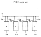
- a communication system is constructed such that units 12a to 12d having communication control functions communicable in the aforementioned common data communication format are coupled through transmission lines 10a to 10d and reception lines 11a to 11d to a common data circuit 9.
- each of the units 12a to 12d comprises a control section 13 and a communication control section 14, and the communication control section 14 includes a transmission section 15 for transmission control to the common data circuit 9, a reception section 16 for reception control from the common data circuit 9, and a collision detection section 17 for priority determination (collision detection) at the time of collision in the bus competitive control mode.
- a collision detection operation of the aforementioned communication system in the bus competitive control mode will be described with reference to a data transmission flow chart of Fig. 9 in addition to Figs. 1, 2 and 10.
- the transmission and reception of data are effected in the predetermined common data communication format as illustrated in Fig. 1.
- the respective units 12a to 12d are coupled through the transmission lines 10a to 10d and the reception lines 11a to 11d to the common data circuit 9 as illustrated in Fig. 2
- the A and B units 12a and 12b generate transmission requests.
- the collision detection operation in the bus competitive control mode in this case will be described hereinbelow with reference to the data transmission flow chart of Fig. 9.
- Fig. 9 In Fig.
- the A unit 12a and B unit 12b generating the transmission requests respectively performs transmission frame assembling works (step 19) in accordance with the data communication format as shown in Fig. 1. Then, the A unit 12a and B unit 12b observe the transmission and reception status on the above-mentioned common data circuit and detect, on the basis of a communication termination signal from the communication data termination area 6 on the Fig. 1 data communication format, that the transmission and reception of data are completed between the other units, thereafter advancing from the transmission frame deferring state decision (step 20) to the transmission start (step 21) state. With this operation, the transmission start phases of the A and B units 12a and 12b are combined, and a transmission start signal area 1 shown in Fig.
- the A unit 12a effecting the transmission start (step 21) in Fig. 9, enters into the priority determining area 2 to perform the collision detection (step 22) in Fig. 9 and confirms that a signal having a priority higher than the priority signal itself is not generated from the other units, then transmitting the communication control area 3, communication data area 4, communication data termination area 5 and transmission completion signal area 6 in Fig.
- the operation advances from the transmission completion decision (step 26) to a transmission error detection (step 27).
- the operation goes to an abnormal termination (step 29) in the case of detection of an error and goes to a normal termination (step 28) in the case of no detection of the error, thereby terminating the transmission.
- the B unit 12b performing the transmission start (step 21), enters into the priority determining area 2 to effect the collision detection (step 22) so as to perform the collision detection.
- the B unit detecting that a signal having a priority higher than its own priority signal is generated from the other unit, performs a transmission stop process (step 23) and then increases the trial count by 1 (step 24) to check whether it exceeds the trial count limitation (step 25). In the case of not exceeding the trial count limitation, the operation again advances to the transmission deferring state decision (step 20). On the other hand, if exceeding the trial count limitation, the operation proceeds to the abnormal termination (step 29).
- the collision detection in the bus competitive mode can be realized, and a series of communication data transmissions from the transmission start signal area 1 to the transmission completion signal area 6 in Fig. 6 are effected with respect to the common data circuit 9 at a fixed transmission speed to perform the data transmission and reception between the respective units.
- the collision detection in the bus competitive control mode is affected by delays of the transmitted communication data due to load resistances or load capacities of the common data circuit and hence the transmission is required to be effected at a speed including a portion corresponding to the delay whereby there is a problem that difficulty is encountered to increase the transfer speed for the transmission and reception between the units.
- the present invention has been developed in order to eliminate the above-described problem, and it is therefore an object of this invention to provide a bus competitive control apparatus which is capable of reducing the affection of the delay of the communication data due to the common data circuit 9 for the collision detection in the bus competitive control mode and, in addition, shortening the time period necessary for the transmission and reception between the units.
- a bus competitive control apparatus is equipped with a speed setting means 34A whereby the transmission speed to the common data circuit for the above-mentioned collision detection field (priority determining area) 2 is lower by a system-allowable value than the speed for a non-collision detection field.
- a bus competitive control apparatus is, for the speed setting means 34A, equipped with a speed setting basic clock 38 for setting the data speeds of the collision detection field 2 (priority determining area) and the non-collision detection field 30 in accordance with a period and a sequence control section 34 whereby the period of the clock is set to become long at every detection of the collision detection field 2 (priority determining area) so as to lower the transmission speed.
- the speed setting means 34A is equipped with a variable means 34m which can relatively vary the transmission speed of the collision detection field 2 (priority determining area) with the transmission speed of the non-collision detection field 30.
- each of the units is provided with a reception section 16 comprising a demodulator 16a for receiving and demodulating the data on the common data circuit 9, and the operating speed of the demodulator 16a is controlled on the basis of the output of the above-mentioned speed setting means 34A so that the speed at the reception time of the collision detection field 2 (priority determining area) is lower than the speed at the reception time of the non-collision detection field 30.
- the speed setting means 34A sets the transmission speed to the transmission speed for the collision detection and transmits the data.
- a transmission rate control section 35 controls the clocks of the transmission section 15 and reception section 16 on the basis of a control signal 37 to be outputted from the sequence control section 34 constituting the speed setting means 34A and the speed setting basic clock 38 set in accordance with the control signal 37 so as to become long in period at every detection of the collision detection field 2, thereby respectively setting the transmission speeds of the collision detection field 2 and the non-collision detection field on the common data circuit 9.
- the period of the speed setting basic clock 38 is varied by the variable means 34m.
- the operating speed of the demodulator 16a is controlled with the clock, set to be longer in period as compared with the reception time of the non-collision detection field 30, so as to be lower than the normal speed to accurately perform the demodulating operation.
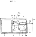
- Fig. 3 shows a bus competitive control apparatus according to this invention where parts corresponding to those in Fig. 10 are indicated by the same references and the description thereof will be omitted.
- the data communication format predetermined for the common data in the bus competitive control apparatus according to this invention is the same as the conventional for mat shown in Fig. 1.
- a plurality of units 12a to 12d having communication control functions are coupled through transmission lines 10a to 10d and reception lines 11a to 11d to a common data circuit 9 so as to construct a communication system.
- each of the units 12a to 12d comprises a control section 13 and a communication control section 14.
- the communication control section 14 comprises a transmission section 15 for performing the transmission control to the common data circuit 9, a reception section 16 for performing the reception control from the common data circuit 9, a collision detection section 17 for effecting the collision detection in the bus competitive control mode, a sequence control section 34 for constituting a speed setting means 34A to control the frame sequence, and a transmission rate control section 35 for receiving a control signal from the sequence control section 34 to control the transmission speed.
- the A unit 12a and B unit 12b observe the transmission and reception states between the other units on the common data circuit 9 and detects the completion of the transmission and reception of the data between the other units on the basis of a communication completion signal of the communication data termination area 6 on the data communication format shown in Fig. 1, thereby advancing from a transmission deferring state decision (step 20) to a transmission start (step 21).
- the above-described operation performs the phase setting at the transmission start of the A unit 12a and B unit 12b.
- a step 31 in Fig. 5 checks and decides the collision detection field.
- the signal initially transmitted in this embodiment is the transmission start signal area 1 of the Fig. 1 data communication format to be the non-collision field, and hence a decision is made such that it is not the collision detection field, whereby in a step 33 the data transmission is made at the normal transmission speed.
- the step 31 is again executed in order to check whether it is the collision detection field.
- the next signal to be transmitted is the priority determining area 2 in Fig. 1 to decide the collision detection area, and hence in a step 32 the transmission speed is set to the collision detection transmission speed and the data transmitting operation is effected.
- the A unit 12a is set to be higher in priority than the B unit 12b, a description will be made hereinbelow in terms of the operation of the A unit 12a having the higher priority.
- the A unit 12a which is in the data transmission state of the priority determining area 2 in Fig. 6 at the collision detection transmission speed, transmits the data at the normal transmission speed (step 33) in the case that the result of the collision detection (step 22) in Fig. 5 shows that the priority signal itself is not in the collision state, and performs the transmission of the remaining non-collision-detected area of the transmission frame in Fig. 6 and the transmissions of the communication control area 3, communication data area 4, communication data termination area 5 and transmission completion signal area 6 and advances through the transmission completion step 26 routine to a transmission error detection (step 27) in Fig. 5. If an error is detected, the A unit 12a proceeds to an abnormal termination (step 29), and if the error is not detected, the A unit 12a proceeds to a normal termination (step 28), thereafter completing the transmission.
- the B unit 12b which enters into the data transmission operation of the priority determining area 2 in Fig. 6 at the collision detection transmission speed, performs the collision detection (step 22) in Fig. 5.
- the B unit 12b effects a transmission stopping (step 23) operation and increases the transmission trial count by 1 (step 24) to check whether the trial count exceeds a trial count limitation (step 25). If not exceeding the trial count limitation, the B unit 12b shifts to again execute the transmission deferring state decision (step 20) process. On the other hand, if exceeding the trial count limitation, the B unit 12b shifts to the abnormal termination (step 29).
- numeral 37 is a control signal outputted from the sequence control section 34 for controlling the transmission sequence to input the collision field to the next step's transmission rate control section 35.
- the transmission rate control section 35 controls the clocks of the transmission section 15 and reception section 16 to respectively control the clocks of the aforementioned transmission section 15 and reception section 16 for the collision detection field 2 and the non-collision detection field 30. According to this operation, it is possible to respectively set the transmission speeds for the collision detection field 2 and non-collision detection field 30 of the transmission frame on the common data circuit 9.
- the period of the speed-setting basic clock 38 becomes Tm to generate a wider pulse whereby the transmission speed is set to be low (second embodiment).
- a variable means 34m is provided so that the above-mentioned period Tm is variable to change the transmission speed to allow the adjustment of the transmission speed in accordance with the load resistance, load capacity and others (third embodiment).
- the reception section 16 there is provided a demodulator 16a whose operating speed is also controlled in accordance with the speed-setting basic clock 38. Since the operating speed is set to be lower as compared with the normal state when receiving the collision detection field 2, it is possible to surely perform the reception operation (fourth embodiment).
- the output of the node B relative to the output of the node A is affected by the aforementioned delay so that an apparent delay 41b occurs, it becomes impossible to make the decision between H and L on the basis of the sampling point 39a so as to make impossible the collision detection at a transmission speed 40a.
- the transmission speed is set to a transmission speed 40 lower than the transmission speed 40a as illustrated by (c) in Fig. 7, the decision between H and L can be made on the basis of a sampling point 39b, thereby allowing the collision detection.
- the transmission speed for the collision detection field being lowered, it is possible to accurately detect the collision.
- the data outputted from the A unit 12a results in the occurrence of a delay 41c in the waveform to be inputted to the reception-target (destination) C unit 12c due to the delay of the above-mentioned data circuit 9, a node C side can make the decision between H and L on the basis of a sampling point 39c, thereby allowing the normal reception. That is, if the delay occurs so that the H interval is relatively equal to the L interval, the transmission and reception of the non-collision detection field can be effected at the highest transmission speed allowed by the unit.
- the waveshaped reception waveform in the reception section 16 of the C unit 12c becomes like a waveform 43d in the C unit 12c and the decision between H and L becomes impossible at the sampling point 39d, thereby making difficult the normal reception.
- the transmission speed is required to be set so as to allow this delay.
- the transmission and reception operations of the data are effected in the bus competitive control apparatus.
- the Figs. 7 and 8 signal waveforms described in the first embodiment are PWM waveforms pulse-width-modulated and the sampling is effected 3 times per 1 bit.
- the collision detection field is executed as the priority determining area 2 in Fig. 2, it is appropriate that the collision detection field is provided at any portions within one frame or the execution is made at a plurality of areas.
- the transmission data is pulse-width-modulated, it is also appropriate that the transmission data is processed in a different modulating method.
- an automatic setting means for automatically setting the speed is incorporated at the initial system-constructing time or at every predetermined time interval. In detail, with the normal speed (the transmission speed for the non-collision detection field) being set as the origin, the delay is gradually enlarged up to the allowable speed so that this allowable speed is set to the delay speed.
- variable resistor 34m is arranged, for example, such that a plurality of dividers are provided and a switching means such as a multiplexer to select one of the plurality of dividers is provided so as to obtain a predetermined period on the basis of the control signal from the control section.
- the speed setting means sets the transmission speed of the collision detection field to the common data circuit to the system-allowable speed lower as compared with the non-collision detection field so that the transmission speed of the collision detection field is set to a transmission speed whereby the delay of the communication data due to the load resistance and the load capacity of the common data circuit does not give the influence on the collision detection, and hence it is possible that the it is set to become low to reach the system-allowable speed and it is possible to reduce the influence of the delay of the communication data due to the common data circuit on the collision detection, thereby allowing an accurate detection of the collision.
- the speed setting basic clock for setting the speeds of the data of the collision detection field and the non-collision detection field on the basis of the period is provided as the speed setting means and the sequence control section is provided which sets the period of the clock to become longer at every detection of the collision detection field to lower the transmission speed, it is possible that the transmission speed of the collision detection field is controlled on the basis of the speed setting basic clock so as to be lowered up to a transmission speed whereby the delay of the communication data on the common data circuit does not affect the collision detection and the transmission speed of the non-collision detection field is lowered up to a transmission speed which does not affect the transmission and reception of the communication data so as to realize an accurate transmission and reception.
- the transmission and reception can be effected at the highest transmission speed in a range which allows the accurate transmission and reception, and the time necessary for the transmission and reception of the transmission frame, produced on the basis of the common data communication format, between the respective units is the sum of the transmission time of the collision detection field and the transmission field of the non-collision detection field, thereby shortening the time necessary for the transmission and reception.
- the speed setting means is equipped with the variable means which can relatively vary the transmission speed of the collision detection field with respect to the transmission speed of the non-collision detection field, the transmission speeds of the collision detection field and non-collision detection field can be adjusted in accordance with the actual delay amount.
- each of the units is equipped with the reception section comprising the demodulator for receiving and demodulating the data on the common data circuit and the operating speed of the demodulator is controlled on the basis of the output of the speed setting means so that the speed at the reception time of the collision detection field is lower than the speed at the reception time of the non-collision detection field, it is possible to accurately perform the reception to heighten the collision detection accuracy.
- a transmission rate control section When a delay of communication data due to a common data circuit obstructs a collision detection between units, a transmission rate control section produces a speed setting basic clock, whose period Tm is set to be long, on the basis of the output of a sequence control section.
- a transmission section and a reception section comprising a demodulator are controlled on the basis of the clock so as to set the transmission speed of a collision detection field to be low, thereby reducing the influence of the delay on the communication data.
Landscapes
- Engineering & Computer Science (AREA)
- Computer Networks & Wireless Communication (AREA)
- Signal Processing (AREA)
- Theoretical Computer Science (AREA)
- Physics & Mathematics (AREA)
- General Engineering & Computer Science (AREA)
- General Physics & Mathematics (AREA)
- Small-Scale Networks (AREA)
- Bus Control (AREA)
Applications Claiming Priority (2)
| Application Number | Priority Date | Filing Date | Title |
|---|---|---|---|
| JP331164/91 | 1991-11-20 | ||
| JP3331164A JP2601962B2 (ja) | 1991-11-20 | 1991-11-20 | バス競合制御装置 |
Publications (2)
| Publication Number | Publication Date |
|---|---|
| EP0543359A1 true EP0543359A1 (fr) | 1993-05-26 |
| EP0543359B1 EP0543359B1 (fr) | 1998-04-15 |
Family
ID=18240598
Family Applications (1)
| Application Number | Title | Priority Date | Filing Date |
|---|---|---|---|
| EP92119698A Expired - Lifetime EP0543359B1 (fr) | 1991-11-20 | 1992-11-19 | Appareil de commande compétitif de bus |
Country Status (4)
| Country | Link |
|---|---|
| US (1) | US5452422A (fr) |
| EP (1) | EP0543359B1 (fr) |
| JP (1) | JP2601962B2 (fr) |
| DE (1) | DE69225114T2 (fr) |
Cited By (3)
| Publication number | Priority date | Publication date | Assignee | Title |
|---|---|---|---|---|
| DE4405297A1 (de) * | 1994-02-19 | 1995-08-24 | Telefonbau & Normalzeit Gmbh | Verfahren zur Synchronisation von Sendeeinrichtungen in Zugangseinheiten bei einem gerichtet betriebenen getakteten Bussystem |
| EP1969799A4 (fr) * | 2005-12-15 | 2014-10-15 | Paradox Security Systems Ltd | Interface de reseau de dispositifs |
| CN112180775A (zh) * | 2019-07-02 | 2021-01-05 | 恩智浦有限公司 | Can总线上的冲突检测 |
Families Citing this family (5)
| Publication number | Priority date | Publication date | Assignee | Title |
|---|---|---|---|---|
| JP4034844B2 (ja) * | 1995-11-28 | 2008-01-16 | 富士通株式会社 | バス延長対応型制御システム |
| WO1998020407A1 (fr) * | 1996-11-07 | 1998-05-14 | Hitachi, Ltd. | Circuit integre a semi-conducteurs et micro-ordinateur |
| US20080002735A1 (en) * | 1997-04-01 | 2008-01-03 | Paradox Security Systems Ltd. | Device network |
| US6266701B1 (en) * | 1997-07-02 | 2001-07-24 | Sitara Networks, Inc. | Apparatus and method for improving throughput on a data network |
| KR100625931B1 (ko) * | 2004-07-29 | 2006-09-20 | 매그나칩 반도체 유한회사 | 비동기적 입력신호의 선입선처리장치 |
Citations (2)
| Publication number | Priority date | Publication date | Assignee | Title |
|---|---|---|---|---|
| EP0183431A2 (fr) * | 1984-11-20 | 1986-06-04 | Unisys Corporation | Système de commande de réseau pour modules de processeurs multiples |
| US5123029A (en) * | 1991-06-21 | 1992-06-16 | International Business Machines Corporation | Broadcast-initiated bipartite frame multi-access protocol |
Family Cites Families (2)
| Publication number | Priority date | Publication date | Assignee | Title |
|---|---|---|---|---|
| US4411004A (en) * | 1980-06-27 | 1983-10-18 | Rolm Corporation | Inductively coupled sensing circuit and priority system |
| NL8702394A (nl) * | 1987-10-08 | 1989-05-01 | Philips Nv | Interface voor een verbindingsnetwerk tussen afzonderlijke stations enerzijds en een voor het berichtenverkeer tussen deze stations gebruikt fysiek medium anderzijds. |
-
1991
- 1991-11-20 JP JP3331164A patent/JP2601962B2/ja not_active Expired - Lifetime
-
1992
- 1992-11-17 US US07/977,499 patent/US5452422A/en not_active Expired - Fee Related
- 1992-11-19 EP EP92119698A patent/EP0543359B1/fr not_active Expired - Lifetime
- 1992-11-19 DE DE69225114T patent/DE69225114T2/de not_active Expired - Fee Related
Patent Citations (2)
| Publication number | Priority date | Publication date | Assignee | Title |
|---|---|---|---|---|
| EP0183431A2 (fr) * | 1984-11-20 | 1986-06-04 | Unisys Corporation | Système de commande de réseau pour modules de processeurs multiples |
| US5123029A (en) * | 1991-06-21 | 1992-06-16 | International Business Machines Corporation | Broadcast-initiated bipartite frame multi-access protocol |
Non-Patent Citations (1)
| Title |
|---|
| ELEKTRONIK no. 1, January 1991, MÜNCHEN,DE pages 56 - 59 SUMM & HEBERLE 'Serieller Gerätebus mit fehlererkennendem Empfänger' * |
Cited By (3)
| Publication number | Priority date | Publication date | Assignee | Title |
|---|---|---|---|---|
| DE4405297A1 (de) * | 1994-02-19 | 1995-08-24 | Telefonbau & Normalzeit Gmbh | Verfahren zur Synchronisation von Sendeeinrichtungen in Zugangseinheiten bei einem gerichtet betriebenen getakteten Bussystem |
| EP1969799A4 (fr) * | 2005-12-15 | 2014-10-15 | Paradox Security Systems Ltd | Interface de reseau de dispositifs |
| CN112180775A (zh) * | 2019-07-02 | 2021-01-05 | 恩智浦有限公司 | Can总线上的冲突检测 |
Also Published As
| Publication number | Publication date |
|---|---|
| DE69225114D1 (de) | 1998-05-20 |
| DE69225114T2 (de) | 1998-09-17 |
| EP0543359B1 (fr) | 1998-04-15 |
| JP2601962B2 (ja) | 1997-04-23 |
| JPH05143530A (ja) | 1993-06-11 |
| US5452422A (en) | 1995-09-19 |
Similar Documents
| Publication | Publication Date | Title |
|---|---|---|
| EP3716555B1 (fr) | Émetteur-récepteur can adaptable et système | |
| EP0112043B1 (fr) | Récepteur binaire autosynchronisant | |
| JP2738106B2 (ja) | 多重通信制御装置 | |
| EP0543359B1 (fr) | Appareil de commande compétitif de bus | |
| US4755990A (en) | Collision avoidance in a multinode data communication network | |
| EP0049952B1 (fr) | Circuit de synchronisation | |
| US5402420A (en) | Communication unit having non-destructive arbitration function | |
| US4990907A (en) | Method and apparatus for data transfer | |
| EP0568804A2 (fr) | Appareil de commande de communications | |
| JPH04222130A (ja) | 干渉検出回路 | |
| EP0173348B1 (fr) | Procédé pour la mise en oeuvre de la commande d'acquisition de rafale dans un système AMRT | |
| US6034955A (en) | Single line interface system and method thereof | |
| US5623515A (en) | Data communication system for reducing a risk of transmission errors | |
| US4807231A (en) | Multiplex communication method | |
| JPH07200010A (ja) | プログラマブルコントローラおよびその排他制御交信方法 | |
| JP3282396B2 (ja) | 信号伝送方法 | |
| JP2806568B2 (ja) | 共通バス制御方式 | |
| EP0187679B1 (fr) | Terminal de transmission de données | |
| KR100220518B1 (ko) | 카 랜 시스템의 데이터 구조와 이를 이용한 시계보정 시스템 | |
| US6944781B2 (en) | Method of communicating data via a bus and bus system for implementing the method | |
| JPH06334668A (ja) | 多重伝送方式 | |
| JPH08328709A (ja) | 周辺装置 | |
| JPH10105511A (ja) | セントロニクスインターフェイス制御装置 | |
| JPH0784669A (ja) | マイクロプロセッサ装置から供給される制御信号の発生時点を決定するための回路装置 | |
| JPS581450B2 (ja) | インタ−フエイス回路 |
Legal Events
| Date | Code | Title | Description |
|---|---|---|---|
| PUAI | Public reference made under article 153(3) epc to a published international application that has entered the european phase |
Free format text: ORIGINAL CODE: 0009012 |
|
| AK | Designated contracting states |
Kind code of ref document: A1 Designated state(s): DE FR GB |
|
| 17P | Request for examination filed |
Effective date: 19930701 |
|
| GRAG | Despatch of communication of intention to grant |
Free format text: ORIGINAL CODE: EPIDOS AGRA |
|
| 17Q | First examination report despatched |
Effective date: 19970626 |
|
| GRAG | Despatch of communication of intention to grant |
Free format text: ORIGINAL CODE: EPIDOS AGRA |
|
| GRAH | Despatch of communication of intention to grant a patent |
Free format text: ORIGINAL CODE: EPIDOS IGRA |
|
| GRAH | Despatch of communication of intention to grant a patent |
Free format text: ORIGINAL CODE: EPIDOS IGRA |
|
| GRAA | (expected) grant |
Free format text: ORIGINAL CODE: 0009210 |
|
| AK | Designated contracting states |
Kind code of ref document: B1 Designated state(s): DE FR GB |
|
| REF | Corresponds to: |
Ref document number: 69225114 Country of ref document: DE Date of ref document: 19980520 |
|
| ET | Fr: translation filed | ||
| PLBE | No opposition filed within time limit |
Free format text: ORIGINAL CODE: 0009261 |
|
| STAA | Information on the status of an ep patent application or granted ep patent |
Free format text: STATUS: NO OPPOSITION FILED WITHIN TIME LIMIT |
|
| 26N | No opposition filed | ||
| PGFP | Annual fee paid to national office [announced via postgrant information from national office to epo] |
Ref country code: FR Payment date: 19991109 Year of fee payment: 8 |
|
| PGFP | Annual fee paid to national office [announced via postgrant information from national office to epo] |
Ref country code: GB Payment date: 19991117 Year of fee payment: 8 |
|
| PGFP | Annual fee paid to national office [announced via postgrant information from national office to epo] |
Ref country code: DE Payment date: 19991119 Year of fee payment: 8 |
|
| PG25 | Lapsed in a contracting state [announced via postgrant information from national office to epo] |
Ref country code: GB Free format text: LAPSE BECAUSE OF NON-PAYMENT OF DUE FEES Effective date: 20001119 |
|
| GBPC | Gb: european patent ceased through non-payment of renewal fee |
Effective date: 20001119 |
|
| PG25 | Lapsed in a contracting state [announced via postgrant information from national office to epo] |
Ref country code: FR Free format text: LAPSE BECAUSE OF NON-PAYMENT OF DUE FEES Effective date: 20010731 |
|
| PG25 | Lapsed in a contracting state [announced via postgrant information from national office to epo] |
Ref country code: DE Free format text: LAPSE BECAUSE OF NON-PAYMENT OF DUE FEES Effective date: 20010801 |
|
| REG | Reference to a national code |
Ref country code: FR Ref legal event code: ST |