EP0543801A2 - Procédé et dispositif destinés à la tomographie - Google Patents
Procédé et dispositif destinés à la tomographie Download PDFInfo
- Publication number
- EP0543801A2 EP0543801A2 EP19930102302 EP93102302A EP0543801A2 EP 0543801 A2 EP0543801 A2 EP 0543801A2 EP 19930102302 EP19930102302 EP 19930102302 EP 93102302 A EP93102302 A EP 93102302A EP 0543801 A2 EP0543801 A2 EP 0543801A2
- Authority
- EP
- European Patent Office
- Prior art keywords
- breast
- frame part
- holders
- radiation
- photographed
- Prior art date
- Legal status (The legal status is an assumption and is not a legal conclusion. Google has not performed a legal analysis and makes no representation as to the accuracy of the status listed.)
- Granted
Links
Images




Classifications
-
- A—HUMAN NECESSITIES
- A61—MEDICAL OR VETERINARY SCIENCE; HYGIENE
- A61B—DIAGNOSIS; SURGERY; IDENTIFICATION
- A61B6/00—Apparatus or devices for radiation diagnosis; Apparatus or devices for radiation diagnosis combined with radiation therapy equipment
- A61B6/50—Apparatus or devices for radiation diagnosis; Apparatus or devices for radiation diagnosis combined with radiation therapy equipment specially adapted for specific body parts; specially adapted for specific clinical applications
- A61B6/502—Apparatus or devices for radiation diagnosis; Apparatus or devices for radiation diagnosis combined with radiation therapy equipment specially adapted for specific body parts; specially adapted for specific clinical applications for diagnosis of breast, i.e. mammography
-
- A—HUMAN NECESSITIES
- A61—MEDICAL OR VETERINARY SCIENCE; HYGIENE
- A61B—DIAGNOSIS; SURGERY; IDENTIFICATION
- A61B6/00—Apparatus or devices for radiation diagnosis; Apparatus or devices for radiation diagnosis combined with radiation therapy equipment
- A61B6/04—Positioning of patients; Tiltable beds or the like
- A61B6/0407—Supports, e.g. tables or beds, for the body or parts of the body
- A61B6/0414—Supports, e.g. tables or beds, for the body or parts of the body with compression means
-
- A—HUMAN NECESSITIES
- A61—MEDICAL OR VETERINARY SCIENCE; HYGIENE
- A61B—DIAGNOSIS; SURGERY; IDENTIFICATION
- A61B6/00—Apparatus or devices for radiation diagnosis; Apparatus or devices for radiation diagnosis combined with radiation therapy equipment
- A61B6/56—Details of data transmission or power supply, e.g. use of slip rings
-
- A—HUMAN NECESSITIES
- A61—MEDICAL OR VETERINARY SCIENCE; HYGIENE
- A61B—DIAGNOSIS; SURGERY; IDENTIFICATION
- A61B6/00—Apparatus or devices for radiation diagnosis; Apparatus or devices for radiation diagnosis combined with radiation therapy equipment
- A61B6/10—Safety means specially adapted therefor
- A61B6/107—Protection against radiation, e.g. shielding
Definitions
- the invention concerns methods in mammog - raphic photography, wherein the breast to be pho - tographed is pressed and spread between holders attached to the photographing apparatus, a beam of X-radiation being directed from one side of said holders through the breast placed between the holders at depicting means placed at the opposite side of the holders in relation to the source of X-radiation, said depicting means being placed inside a film cassette or equivalent placed in connection with the frame of the apparatus.
- the invention further concerns mammographic apparatuses intended for carrying out the method of the invention, said apparatuses comprising a frame part, on which a turnable frame part is mounted, most appropriately as turnable around a horizontal axis, and in which said frame part a source of radiation and means for holding the film cassette as well as holders for the breast to be photographed, to be placed between the source of radiation and said cassette supporting means, are fitted, which said breast holders are displaceable relative one another so as to press the breast to be photographed between said holders.
- Mammography means a method of radioscopy of breasts, wherein a roentgenogram is taken of the breasts.
- the breast is pressed and spread in a way known in prior art between the holders in the photographing apparatus.
- Biopsy photography means a method wherein the breast is pho - tographed by using a so-called biopsy plate so that the openings in the biopsy plate become visi - ble in the roentgenogram.
- biopsy photography the film is developed while the breast to be pho - tographed is kept in its holders, and the finding, if any, is located with the aid of the holes in the biopsy plate, and with their aid a sample is taken from a suspected location.
- an object of the invention is to provide a mammographic apparatus in which the various roentgenograms can be taken without having to shift the patient or to adjust the level of the apparatus when moving from one projection or mode of photography to the other.
- a further object of the invention is to provide a mammographic apparatus which can be automated to a very high extent.
- a mammographic method in accordance with the invention is mainly characterized in that the breast to be photographed is placed on the top face of the lower holder, against which the breast to be photographed is pressed from the root portion of its upper side by means of the outer tip portion of the upper press member, that the upper press member is displaced by pivoting it around its articulation point so that it becomes substantially parallel to the support plane of the lower holder in the frame part that is stationary relative the source of radiation and the part for holding the depicting means, and that when the upper and lower holders become substantially parallel to one another, if necessary, the pressing of the breast is continued further by displacing the upper press member in its linear guides so that it retains its orientation.
- An apparatus in accordance with the invention is mainly characterized in that said upper holder is fitted pivotable around an axis substantially perpendicular to the central axis of the breast, so that the breast to be photographed is pressed by means of the outer tip of the upper holder, at the initial stage of the pressing, from above the breast at its root, and that hereupon, when the upper holder is being shifted downwards, it is pivotable around its articulation shaft so that it becomes substantially parallel to the plane of the lower holder.
- Figures A and B show a known solution of mammographic apparatus, which illustrates the prior art.
- Figures A and B show a prior-art solution of mammographic apparatus, wherein the part 3 that supports the tube head 2 and the depicting means is mounted at its centre P of gravity on the vertical frame 4 of the apparatus 1.
- the apparatus 1 requires a locking device.
- the apparatus of this prior-art solution causes a necessity both to adjust the height and to shift the patient laterally on moving from one projection C, D, E to the other, which makes the photographing slower and more difficult and prevents automation of the apparatus on moving from one projection to the other.
- the apparatus comprises a vertically displaceable vertical frame 4, to which a part turnable around a horizontal axis b - is attached, said part comprising the tube head 2 and the press plates 6 and 7 as well as the film holder 3.
- the vertical frame 4 is arranged displaceable in the vertical direction on the frame part 54, said frame part 54 comprising a vertical guide or guides 57.
- a motor 51 is fixed, by means of which the transfer screw 52 is rotated.
- a gas spring 58 is fitted between the frame 4 and the pedestal 55, said gas spring 58 being attached from one of its ends to the displaceable frame 4 by means of a projection part 59.
- the part 3 that supports the tube head 2 and the depicting means is mounted on the vertical frame 4 of the apparatus 1 at the central axis a - a of the breast M 1 that is pressed between the upper press member 6 and the lower press member 7.
- the apparatus in accordance with the in - vention eliminates any necessity to readjust the apparatus or the position of the patient when moving from one projection f,g,h (different positions M 1 , M 2 , and M 3 of the breasts) to the other.
- the apparatus in accordance with the present invention requires particular operations to coun - terbalance the apparatus (will be described in more detail in relation to Fig. 3), but said particular operations are reasonable in view of the advantage that is achieved.
- the operation of the apparatus is motorized, so that complete counterbalancing is not indispensable or even needed.
- the upper press member 6 is mounted on the rod 10 by means of a linear journalling 9.
- the tip 6' of the downwardly inclined upper press member 6 grasps the breast M 1 at its root J, whereinafter the upper press member 6 is pivoted around its tip 6' at the same time as the upper press member 6 moves in its linear journalling 9 along the guide bar 10 and is pivoted around its articulation point 8.
- the articulation point 8 is provided with an adjust - able spring loading, which permits pivoting of the upper press member 6 until it reaches its normal position 6a, i.e. the position parallel to the lower press plate, whereupon the pressing of the breast M 1 can be increased further if necessary while the press member 6a retains its orientation.
- FIG. 3 the apparatus 1 in accordance with the invention is shown in the position after biopsy photography, corresponding to the removal of the film cassette. Thereat the breast M 1 is still pressed between the upper press member 6 and the lower press member 7, but the cassette rack 22 and the tube head 2 have been run slightly downwards by means of the motor 12 and the screw 13 for removal of the cassette 21.
- a revolving part 25 is supported on the vertical frame 4 of the apparatus 1 by means of bearings 30, said part 25 being provided with a stationary lower press plate 7.
- the film holder 22 itself and the tube head 2 are attached to a common frame part 10, which is mounted by means of a linear journalling 23 on the part 25 revolving around the horizontal axis b - b.
- the upper press member 6 moves relative the frame part 10 in its journalling 9, and the lower press member 7 is stationary.
- the vertical frame part 10 is displaced by means of the motor 12 and the screw 13.
- the revolving part 25 comprises a spiral gear 14, to which a spiral screw 15 as well as a primary gear 16 and a rotating motor 17 are connected.
- the movement of rotation is counterbalanced by means of a balancing gas spring 18, one of whose ends is connected to the wheel 14 by means of a lever, while the other end is connected to the vertical frame 4 of the apparatus 1 by means of an arm 18a.
- the rotation of the part 25 also takes place around the central axis a - a of the breast M, because the central axis a-a substantially coincides with the axis b - b of rotation of the part 25.
- the apparatus 1 in accordance with the in - vention includes readiness for biopsy photography, so that separate installation of an additional part is not necessary when moving over to biopsy photography; only the upper press plate 6 must be exchanged.
- the upper press plate 6 is chosen in accordance with the film size used.
- the film sizes may be, e.g., 18 x 24 cm or 24 x 30 cm.
- Different types of upper press plates 6 of different sizes are needed for the apparatus 1 in accordance with the invention, for both film sizes, the plates needed for biopsy photography, as well as the spot photog - raphy plates.
- the upper press plates 6 are made of a material readily penetrable by X-radiation most appropriately, e.g., so that the transparent part is made of polycarbonate or acrylic and connected to the width-adjustment unit shown in Fig. 9. In this way the press plates can be made simple and inexpensive.
- Fig. 4 shows the shields used in the device 1 in accordance with the invention.
- the upper shield 26 is linked 27 with the upper press member 6 and attached by means of its guide groove 28 to the tube head 2.
- the lower shield curtain 29 is attached to the part 3 that supports the depicting means and to the lower press member 7.
- the upper shield 26 protects the head and jaw and the shoulders of the person to be photographed as well as, in the case of fat persons, any extra fatty tissue from the radiation beam R.
- the lower shield curtain is needed mainly only in enlarged photography to prevent access of fatty tissue of the person to be photographed between the lower press member 6 and the part 3 that supports the depicting means.
- Fig. 5 shows the apparatus 1 in accordance with the invention in the normal photographing po - sition.
- the lower press plate 7 has been run into contact with the part 3 that supports the depicting means 21. From normal photography it is possible to move over to enlarged photography and to biopsy photography without removing the breast M 1 (from between the upper press member 6 and the lower press member 7).
- Fig. 6 shows the apparatus in accordance with the invention in the biopsy photography position.
- Fig. 7 shows the apparatus 1 in accordance with the invention in enlarged photography.
- the ratio of enlarge - ment can be chosen freely.
- the ratio of enlargement in enlarged photography is 1.5:1, but in the solution in accordance with the invention the ratio of enlargement can be chosen and adjusted continuously.
- Fig. 8 is a schematical illustration of the mechanism of articulation of the upper press member 6, which said mechanism permits the upper press member 6 to grasp the breast M at its root in accordance with what is explained in con - nection with Fig. 2, thereby leaving space for the hands of the nurse to "stretch" the breast at the initial stage of the pressing.
- the pressing can be continued in the same way as in prior-art solutions.
- its tip 6' remains on the vertical line denoted with a dotted - dashed line in Fig. 8.
- the part denoted with the reference numeral 9' is a sledge that can move in the direction of pressing and that belongs to the mechanism.
- the parts of the articulation mechanism of the press member 6 also include a lever 32, which is con - nected to the casing 34 of the linear bearing by the intermediate of the rod 33, said casing being, e.g., a cross - piece, whose articulation pins are, in Fig. 8, denoted with the reference numeral 35.
- an adjustable spring 31 the force is determined that is opposed to the pivoting of the press member to the horizontal position, i.e. the force with which the tip 6' of the press member presses the breast.
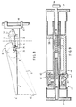
- Fig. 9 illustrates the width-adjustment mechanism of the exchangeable press plates 6, which said mechanism is provided with an emergency - release torque switch.
- the width-adjustment wheel 36 is in direct contact with the holders, e.g. brackets 37, to which the press plates 6 are attached. Between the shaft 42 and the brackets 37, there are parts 38 which permit only axial movement.
- the frame 39 of the width - ad - justment mechanism is attached to the rods 33 shown in Fig. 8.
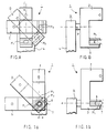
- FIG. 10a shows a press plate 6A, e.g., for a photographing press member of a size of 30 x 24 cm.
- the press plate can be placed into a regulating mechanism 42 which can be adjusted for different widths.
Landscapes
- Health & Medical Sciences (AREA)
- Life Sciences & Earth Sciences (AREA)
- Engineering & Computer Science (AREA)
- Medical Informatics (AREA)
- Heart & Thoracic Surgery (AREA)
- Animal Behavior & Ethology (AREA)
- Biophysics (AREA)
- High Energy & Nuclear Physics (AREA)
- Veterinary Medicine (AREA)
- Nuclear Medicine, Radiotherapy & Molecular Imaging (AREA)
- Optics & Photonics (AREA)
- Pathology (AREA)
- Radiology & Medical Imaging (AREA)
- Biomedical Technology (AREA)
- Public Health (AREA)
- Molecular Biology (AREA)
- Surgery (AREA)
- Physics & Mathematics (AREA)
- General Health & Medical Sciences (AREA)
- Dentistry (AREA)
- Oral & Maxillofacial Surgery (AREA)
- Computer Networks & Wireless Communication (AREA)
- Apparatus For Radiation Diagnosis (AREA)
- Organic Low-Molecular-Weight Compounds And Preparation Thereof (AREA)
- Massaging Devices (AREA)
- Vending Machines For Individual Products (AREA)
- Treatment Of Water By Ion Exchange (AREA)
- Peptides Or Proteins (AREA)
- Vaporization, Distillation, Condensation, Sublimation, And Cold Traps (AREA)
- Confectionery (AREA)
- Feeding, Discharge, Calcimining, Fusing, And Gas-Generation Devices (AREA)
Applications Claiming Priority (3)
| Application Number | Priority Date | Filing Date | Title |
|---|---|---|---|
| FI882490 | 1988-05-26 | ||
| FI882490A FI80996C (fi) | 1988-05-26 | 1988-05-26 | Mammografiamenetelmä ja -laite |
| EP89905117A EP0370089B2 (fr) | 1988-05-26 | 1989-05-04 | Appareils de mammographie |
Related Parent Applications (2)
| Application Number | Title | Priority Date | Filing Date |
|---|---|---|---|
| EP89905117A Division EP0370089B2 (fr) | 1988-05-26 | 1989-05-04 | Appareils de mammographie |
| EP89905117.1 Division | 1989-05-04 |
Publications (3)
| Publication Number | Publication Date |
|---|---|
| EP0543801A2 true EP0543801A2 (fr) | 1993-05-26 |
| EP0543801A3 EP0543801A3 (en) | 1993-08-11 |
| EP0543801B1 EP0543801B1 (fr) | 1998-08-05 |
Family
ID=8526526
Family Applications (2)
| Application Number | Title | Priority Date | Filing Date |
|---|---|---|---|
| EP93102302A Expired - Lifetime EP0543801B1 (fr) | 1988-05-26 | 1989-05-04 | Dispositifs destinés à la mammographie |
| EP89905117A Expired - Lifetime EP0370089B2 (fr) | 1988-05-26 | 1989-05-04 | Appareils de mammographie |
Family Applications After (1)
| Application Number | Title | Priority Date | Filing Date |
|---|---|---|---|
| EP89905117A Expired - Lifetime EP0370089B2 (fr) | 1988-05-26 | 1989-05-04 | Appareils de mammographie |
Country Status (7)
| Country | Link |
|---|---|
| US (1) | US5050197A (fr) |
| EP (2) | EP0543801B1 (fr) |
| JP (1) | JP2672383B2 (fr) |
| AT (1) | ATE169201T1 (fr) |
| DE (2) | DE68928770T2 (fr) |
| FI (1) | FI80996C (fr) |
| WO (1) | WO1989011248A1 (fr) |
Cited By (5)
| Publication number | Priority date | Publication date | Assignee | Title |
|---|---|---|---|---|
| WO2001049178A1 (fr) * | 1999-12-30 | 2001-07-12 | The Brigham And Women's Hospital, Inc. | Appareil de compression permettant d'examiner un tissu mammaire du point de vue diagnostique |
| FR2842722A1 (fr) * | 2002-07-29 | 2004-01-30 | Ge Med Sys Global Tech Co Llc | Mammographie a compression simplifiee |
| EP1759637A3 (fr) * | 2005-08-15 | 2007-07-25 | Hologic, Inc. | Mammographie et tomosynthèse à rayons X du sein d'une patiente |
| US10792003B2 (en) | 2010-10-05 | 2020-10-06 | Hologic, Inc. | X-ray breast tomosynthesis enhancing spatial resolution including in the thickness direction of a flattened breast |
| US11191502B2 (en) | 2010-10-05 | 2021-12-07 | Hologic, Inc. | Upright x-ray breast imaging with a CT mode, multiple tomosynthesis modes, and a mammography mode |
Families Citing this family (32)
| Publication number | Priority date | Publication date | Assignee | Title |
|---|---|---|---|---|
| FI85803C (fi) * | 1989-11-23 | 1992-06-10 | Planmed Oy | Foerfarande och anordning foer styrning av funktioner av en mammografiroentgenanordning. |
| US6031892A (en) * | 1989-12-05 | 2000-02-29 | University Of Massachusetts Medical Center | System for quantitative radiographic imaging |
| SE466333B (sv) * | 1991-02-05 | 1992-02-03 | Siemens Elema Ab | Straalundersoekningsapparat foer broestundersoekningar |
| US5594769A (en) * | 1991-11-27 | 1997-01-14 | Thermotrex Corporation | Method and apparatus for obtaining stereotactic mammographic guided needle breast biopsies |
| US5289520A (en) * | 1991-11-27 | 1994-02-22 | Lorad Corporation | Stereotactic mammography imaging system with prone position examination table and CCD camera |
| FR2697741B1 (fr) * | 1992-11-10 | 1995-02-03 | Gen Electric Cgr | Dispositif de compression pour appareil radiologique. |
| DE4300796A1 (de) * | 1993-01-14 | 1994-07-21 | Philips Patentverwaltung | Röntgengerät mit einem um eine horizontale Schwenkachse schwenkbaren Geräteteil |
| JPH07303633A (ja) | 1994-05-11 | 1995-11-21 | Mitsubishi Electric Corp | X線乳房撮影装置 |
| US5506877A (en) * | 1994-11-23 | 1996-04-09 | The General Hospital Corporation | Mammography breast compression device and method |
| US5706327A (en) * | 1996-02-09 | 1998-01-06 | Trex Medical Corporation | Method and apparatus for mammographic compression |
| US6142667A (en) * | 1998-09-21 | 2000-11-07 | Oec Medical Systems, Inc. | Gas-spring assisted, counter-balanced L-arm assembly for fluoroscopic imaging |
| US6675037B1 (en) * | 1999-09-29 | 2004-01-06 | Regents Of The University Of Minnesota | MRI-guided interventional mammary procedures |
| SE0103474D0 (sv) * | 2001-10-18 | 2001-10-18 | Siemens Elema Ab | Röntgendiagnostikapparat för mammografiundersökningar |
| SE0201211D0 (sv) * | 2002-04-23 | 2002-04-23 | Siemens Elema Ab | Röntgendiagnostikapparat för mammografiundersökni ngar |
| SE0201806D0 (sv) | 2002-06-13 | 2002-06-13 | Siemens Elema Ab | Röntgendiagnostikapparat för mammografi undersökningar |
| US6999553B2 (en) * | 2003-03-04 | 2006-02-14 | Livingston Products, Inc. | Method and apparatus for x-ray mammography imaging |
| DE10353611B4 (de) | 2003-11-17 | 2013-01-17 | Siemens Aktiengesellschaft | Röntgendiagnostikgerät für Mammographieuntersuchungen |
| CN100594843C (zh) * | 2004-08-03 | 2010-03-24 | 株式会社东芝 | 图像显示装置、图像显示方法、存储介质以及程序 |
| DE102004052614B3 (de) * | 2004-10-29 | 2006-01-05 | Siemens Ag | Kompressionsplatte, insbesondere für ein Mammographiegerät |
| JP4600942B2 (ja) * | 2005-10-06 | 2010-12-22 | 富士フイルム株式会社 | 乳房画像撮影装置 |
| JP4769097B2 (ja) * | 2006-03-01 | 2011-09-07 | 富士フイルム株式会社 | マンモグラフィ装置及び該マンモグラフィ装置に用いられる乳房圧迫板 |
| JP4950612B2 (ja) | 2006-09-29 | 2012-06-13 | 富士フイルム株式会社 | 乳房撮影装置、乳房押圧板及び乳房固定方法 |
| FI123261B (fi) | 2008-11-28 | 2013-01-15 | Planmed Oy | 3D mammografia |
| JP2012176122A (ja) * | 2011-02-25 | 2012-09-13 | Canon Inc | 放射線撮影装置および放射線検出システム |
| JP5355619B2 (ja) * | 2011-04-27 | 2013-11-27 | 富士フイルム株式会社 | 放射線画像撮影装置 |
| KR102080176B1 (ko) * | 2012-03-29 | 2020-02-21 | 제네럴 일렉트릭 컴퍼니 | 맘모그래피 장치 |
| DE102012212136A1 (de) | 2012-07-11 | 2014-01-16 | Siemens Aktiengesellschaft | Vorrichtung und Verfahren für ein Diagnostikgerät |
| CN105228526B (zh) * | 2013-03-29 | 2018-06-08 | 通用电气公司 | 乳房造影装置 |
| JP6151432B2 (ja) * | 2013-03-29 | 2017-06-21 | ゼネラル・エレクトリック・カンパニイ | マンモグラフィ装置及びその位置整列制御方法 |
| CN109171779A (zh) * | 2018-10-08 | 2019-01-11 | 北京万东医疗科技股份有限公司 | 对乳腺机非等中心控制臂的控制方法及装置 |
| KR102314303B1 (ko) | 2019-04-16 | 2021-10-20 | 주식회사 디알텍 | 방사선 촬영장치 및 방사선 촬영방법 |
| US12357236B2 (en) * | 2022-12-15 | 2025-07-15 | Wisconsin Alumni Research Foundation | Breast biopsy immobilization device for magnetic resonance imaging |
Family Cites Families (11)
| Publication number | Priority date | Publication date | Assignee | Title |
|---|---|---|---|---|
| US3609355A (en) * | 1968-05-31 | 1971-09-28 | Schick X Ray Co Inc | X-ray mammograph in which the x-ray source and film cassette are rotatable about the subject being photograph |
| JPS5564265A (en) * | 1978-11-08 | 1980-05-14 | Hitachi Ltd | Recording state judging device |
| US4433690A (en) † | 1981-07-20 | 1984-02-28 | Siemens Ag | Compact ultrasound apparatus for medical examination |
| DE3319622A1 (de) * | 1983-05-30 | 1984-12-06 | Siemens AG, 1000 Berlin und 8000 München | Roentgendiagnostikgeraet fuer mammographieaufnahmen |
| US4768516A (en) * | 1983-10-14 | 1988-09-06 | Somanetics Corporation | Method and apparatus for in vivo evaluation of tissue composition |
| DE3339775A1 (de) * | 1983-11-03 | 1985-05-15 | Siemens AG, 1000 Berlin und 8000 München | Roentgendiagnostikgeraet mit strahlenfiltern |
| DE8332063U1 (de) * | 1983-11-08 | 1984-01-05 | Siemens AG, 1000 Berlin und 8000 München | Röntgendiagnostikgerät mit einem Kompressionswagen |
| SE8306243L (sv) * | 1983-11-14 | 1985-05-15 | Cytex Medicinteknik Ab | Lokaliseringsmetodik |
| US4599738A (en) * | 1984-04-17 | 1986-07-08 | Patrick Panetta | Universal mammography compression system |
| JPH074354B2 (ja) * | 1984-10-29 | 1995-01-25 | 富士写真フイルム株式会社 | 放射線画像情報記録読取装置 |
| JPS61170441A (ja) * | 1985-01-23 | 1986-08-01 | 横河メディカルシステム株式会社 | 放射線断層撮影装置のガントリ− |
-
1988
- 1988-05-26 FI FI882490A patent/FI80996C/fi not_active IP Right Cessation
-
1989
- 1989-05-04 WO PCT/FI1989/000082 patent/WO1989011248A1/fr not_active Ceased
- 1989-05-04 DE DE68928770T patent/DE68928770T2/de not_active Expired - Fee Related
- 1989-05-04 JP JP1504518A patent/JP2672383B2/ja not_active Expired - Lifetime
- 1989-05-04 DE DE68913662T patent/DE68913662T3/de not_active Expired - Lifetime
- 1989-05-04 EP EP93102302A patent/EP0543801B1/fr not_active Expired - Lifetime
- 1989-05-04 US US07/438,460 patent/US5050197A/en not_active Expired - Lifetime
- 1989-05-04 AT AT93102302T patent/ATE169201T1/de not_active IP Right Cessation
- 1989-05-04 EP EP89905117A patent/EP0370089B2/fr not_active Expired - Lifetime
Cited By (11)
| Publication number | Priority date | Publication date | Assignee | Title |
|---|---|---|---|---|
| WO2001049178A1 (fr) * | 1999-12-30 | 2001-07-12 | The Brigham And Women's Hospital, Inc. | Appareil de compression permettant d'examiner un tissu mammaire du point de vue diagnostique |
| US6507748B2 (en) | 1999-12-30 | 2003-01-14 | The Brigham And Women's Hospital, Inc. | Compression apparatus for diagnostically examining breast tissue |
| FR2842722A1 (fr) * | 2002-07-29 | 2004-01-30 | Ge Med Sys Global Tech Co Llc | Mammographie a compression simplifiee |
| EP1759637A3 (fr) * | 2005-08-15 | 2007-07-25 | Hologic, Inc. | Mammographie et tomosynthèse à rayons X du sein d'une patiente |
| US7583786B2 (en) | 2005-08-15 | 2009-09-01 | Hologic, Inc. | X-ray mammography/tomosynthesis of patient's breast |
| US7881428B2 (en) | 2005-08-15 | 2011-02-01 | Hologic, Inc. | X-ray mammography/tomosynthesis of patient's breast |
| EP2837331A2 (fr) * | 2005-08-15 | 2015-02-18 | Hologic, Inc. | Mammographie et tomosynthèse à rayons X du sein d'une patiente |
| US10792003B2 (en) | 2010-10-05 | 2020-10-06 | Hologic, Inc. | X-ray breast tomosynthesis enhancing spatial resolution including in the thickness direction of a flattened breast |
| US11191502B2 (en) | 2010-10-05 | 2021-12-07 | Hologic, Inc. | Upright x-ray breast imaging with a CT mode, multiple tomosynthesis modes, and a mammography mode |
| US11478206B2 (en) | 2010-10-05 | 2022-10-25 | Hologic, Inc. | X-ray breast tomosynthesis enhancing spatial resolution including in the thickness direction of a flattened breast |
| US12144668B2 (en) | 2010-10-05 | 2024-11-19 | Hologic, Inc. | Upright x-ray breast imaging with a CT mode, multiple tomosynthesis modes, and a mammography mode |
Also Published As
| Publication number | Publication date |
|---|---|
| EP0543801A3 (en) | 1993-08-11 |
| FI882490A0 (fi) | 1988-05-26 |
| JPH02504353A (ja) | 1990-12-13 |
| EP0370089B2 (fr) | 2004-04-14 |
| ATE169201T1 (de) | 1998-08-15 |
| DE68928770D1 (de) | 1998-09-10 |
| DE68928770T2 (de) | 1998-12-10 |
| EP0370089B1 (fr) | 1994-03-09 |
| FI80996B (fi) | 1990-05-31 |
| WO1989011248A1 (fr) | 1989-11-30 |
| US5050197A (en) | 1991-09-17 |
| DE68913662D1 (de) | 1994-04-14 |
| EP0370089A1 (fr) | 1990-05-30 |
| DE68913662T2 (de) | 1994-07-07 |
| EP0543801B1 (fr) | 1998-08-05 |
| FI80996C (fi) | 1991-10-25 |
| JP2672383B2 (ja) | 1997-11-05 |
| FI882490A7 (fi) | 1989-11-27 |
| DE68913662T3 (de) | 2004-10-07 |
Similar Documents
| Publication | Publication Date | Title |
|---|---|---|
| EP0543801B1 (fr) | Dispositifs destinés à la mammographie | |
| US3609355A (en) | X-ray mammograph in which the x-ray source and film cassette are rotatable about the subject being photograph | |
| JP3946832B2 (ja) | 検査テーブル | |
| US4752948A (en) | Mobile radiography alignment device | |
| US5023899A (en) | Method and arrangement for X-ray photography or the like | |
| US4979196A (en) | Mammograph | |
| US3908126A (en) | X-ray apparatus for providing panoramic radiographic projections | |
| US7688940B2 (en) | Mammography system and method employing offset compression paddles, automatic collimation, and retractable anti-scatter grid | |
| JPH02301741A (ja) | 寸法および位置を適合させることが可能な乳房x線撮影用のカセットキャリア | |
| EP0499595B1 (fr) | Procédé et dispositif pour radiographies panoramiques | |
| EP0734641B1 (fr) | Dispositif medical radiographique, panoramique et portable | |
| US4339825A (en) | Bi-plane angiographic apparatus | |
| US3991317A (en) | X-ray examining apparatus | |
| US3030508A (en) | X-ray apparatus | |
| US4455671A (en) | X-Ray cassette holder | |
| US4321472A (en) | Panoramic dental X-ray machine with camera detached therefrom | |
| FI82368C (fi) | Mammografifoerfarande och -anordning. | |
| RU2822078C2 (ru) | Устройство формирования изображения для компьютерной томографии | |
| CN221125008U (zh) | 一种影像诊断装置 | |
| US4216383A (en) | Expeditious uni-directional panoramic dental radiography | |
| RU2822078C9 (ru) | Устройство формирования изображения для компьютерной томографии | |
| CN219676383U (zh) | 一种影像科诊断移动式阅片装置 | |
| JPH067332A (ja) | X線検査装置 | |
| CN215416113U (zh) | 一种放射科移动式观看x光片装置 | |
| WO2003071948A1 (fr) | Appareil integre d'examen radiographique numerique |
Legal Events
| Date | Code | Title | Description |
|---|---|---|---|
| PUAI | Public reference made under article 153(3) epc to a published international application that has entered the european phase |
Free format text: ORIGINAL CODE: 0009012 |
|
| AC | Divisional application: reference to earlier application |
Ref document number: 370089 Country of ref document: EP |
|
| AK | Designated contracting states |
Kind code of ref document: A2 Designated state(s): AT BE CH DE FR GB IT LI LU NL SE |
|
| RIN1 | Information on inventor provided before grant (corrected) |
Inventor name: STROEMMER, PEKKA Inventor name: MALMEN, KARI Inventor name: VIRTA, ARTO |
|
| PUAL | Search report despatched |
Free format text: ORIGINAL CODE: 0009013 |
|
| AK | Designated contracting states |
Kind code of ref document: A3 Designated state(s): AT BE CH DE FR GB IT LI LU NL SE |
|
| 17P | Request for examination filed |
Effective date: 19940131 |
|
| 17Q | First examination report despatched |
Effective date: 19950509 |
|
| GRAG | Despatch of communication of intention to grant |
Free format text: ORIGINAL CODE: EPIDOS AGRA |
|
| GRAG | Despatch of communication of intention to grant |
Free format text: ORIGINAL CODE: EPIDOS AGRA |
|
| GRAH | Despatch of communication of intention to grant a patent |
Free format text: ORIGINAL CODE: EPIDOS IGRA |
|
| GRAH | Despatch of communication of intention to grant a patent |
Free format text: ORIGINAL CODE: EPIDOS IGRA |
|
| RAP1 | Party data changed (applicant data changed or rights of an application transferred) |
Owner name: PLANMED OY |
|
| GRAA | (expected) grant |
Free format text: ORIGINAL CODE: 0009210 |
|
| AC | Divisional application: reference to earlier application |
Ref document number: 370089 Country of ref document: EP |
|
| AK | Designated contracting states |
Kind code of ref document: B1 Designated state(s): AT BE CH DE FR GB IT LI LU NL SE |
|
| PG25 | Lapsed in a contracting state [announced via postgrant information from national office to epo] |
Ref country code: NL Free format text: LAPSE BECAUSE OF FAILURE TO SUBMIT A TRANSLATION OF THE DESCRIPTION OR TO PAY THE FEE WITHIN THE PRESCRIBED TIME-LIMIT Effective date: 19980805 Ref country code: LI Free format text: LAPSE BECAUSE OF FAILURE TO SUBMIT A TRANSLATION OF THE DESCRIPTION OR TO PAY THE FEE WITHIN THE PRESCRIBED TIME-LIMIT Effective date: 19980805 Ref country code: CH Free format text: LAPSE BECAUSE OF FAILURE TO SUBMIT A TRANSLATION OF THE DESCRIPTION OR TO PAY THE FEE WITHIN THE PRESCRIBED TIME-LIMIT Effective date: 19980805 Ref country code: BE Free format text: LAPSE BECAUSE OF FAILURE TO SUBMIT A TRANSLATION OF THE DESCRIPTION OR TO PAY THE FEE WITHIN THE PRESCRIBED TIME-LIMIT Effective date: 19980805 Ref country code: AT Free format text: LAPSE BECAUSE OF FAILURE TO SUBMIT A TRANSLATION OF THE DESCRIPTION OR TO PAY THE FEE WITHIN THE PRESCRIBED TIME-LIMIT Effective date: 19980805 |
|
| REF | Corresponds to: |
Ref document number: 169201 Country of ref document: AT Date of ref document: 19980815 Kind code of ref document: T |
|
| REG | Reference to a national code |
Ref country code: CH Ref legal event code: EP |
|
| REF | Corresponds to: |
Ref document number: 68928770 Country of ref document: DE Date of ref document: 19980910 |
|
| ET | Fr: translation filed | ||
| NLV1 | Nl: lapsed or annulled due to failure to fulfill the requirements of art. 29p and 29m of the patents act | ||
| REG | Reference to a national code |
Ref country code: CH Ref legal event code: PL |
|
| PG25 | Lapsed in a contracting state [announced via postgrant information from national office to epo] |
Ref country code: LU Free format text: LAPSE BECAUSE OF NON-PAYMENT OF DUE FEES Effective date: 19990504 Ref country code: GB Free format text: LAPSE BECAUSE OF NON-PAYMENT OF DUE FEES Effective date: 19990504 |
|
| PLBE | No opposition filed within time limit |
Free format text: ORIGINAL CODE: 0009261 |
|
| STAA | Information on the status of an ep patent application or granted ep patent |
Free format text: STATUS: NO OPPOSITION FILED WITHIN TIME LIMIT |
|
| 26N | No opposition filed | ||
| GBPC | Gb: european patent ceased through non-payment of renewal fee |
Effective date: 19990504 |
|
| PGFP | Annual fee paid to national office [announced via postgrant information from national office to epo] |
Ref country code: SE Payment date: 20070425 Year of fee payment: 19 |
|
| PGFP | Annual fee paid to national office [announced via postgrant information from national office to epo] |
Ref country code: DE Payment date: 20070426 Year of fee payment: 19 |
|
| PGFP | Annual fee paid to national office [announced via postgrant information from national office to epo] |
Ref country code: IT Payment date: 20070523 Year of fee payment: 19 |
|
| PG25 | Lapsed in a contracting state [announced via postgrant information from national office to epo] |
Ref country code: DE Free format text: LAPSE BECAUSE OF NON-PAYMENT OF DUE FEES Effective date: 20081202 |
|
| PG25 | Lapsed in a contracting state [announced via postgrant information from national office to epo] |
Ref country code: IT Free format text: LAPSE BECAUSE OF NON-PAYMENT OF DUE FEES Effective date: 20080504 |
|
| PGFP | Annual fee paid to national office [announced via postgrant information from national office to epo] |
Ref country code: FR Payment date: 20080430 Year of fee payment: 20 |
|
| PG25 | Lapsed in a contracting state [announced via postgrant information from national office to epo] |
Ref country code: SE Free format text: LAPSE BECAUSE OF NON-PAYMENT OF DUE FEES Effective date: 20080505 |