EP0544155B1 - Schwenkbare Bildschirmröhre für Video-Spielgeräte - Google Patents
Schwenkbare Bildschirmröhre für Video-Spielgeräte Download PDFInfo
- Publication number
- EP0544155B1 EP0544155B1 EP92119370A EP92119370A EP0544155B1 EP 0544155 B1 EP0544155 B1 EP 0544155B1 EP 92119370 A EP92119370 A EP 92119370A EP 92119370 A EP92119370 A EP 92119370A EP 0544155 B1 EP0544155 B1 EP 0544155B1
- Authority
- EP
- European Patent Office
- Prior art keywords
- monitor tube
- gaming machine
- machine according
- video gaming
- tube
- Prior art date
- Legal status (The legal status is an assumption and is not a legal conclusion. Google has not performed a legal analysis and makes no representation as to the accuracy of the status listed.)
- Expired - Lifetime
Links
Images


Classifications
-
- A—HUMAN NECESSITIES
- A63—SPORTS; GAMES; AMUSEMENTS
- A63F—CARD, BOARD, OR ROULETTE GAMES; INDOOR GAMES USING SMALL MOVING PLAYING BODIES; VIDEO GAMES; GAMES NOT OTHERWISE PROVIDED FOR
- A63F13/00—Video games, i.e. games using an electronically generated display having two or more dimensions
- A63F13/60—Generating or modifying game content before or while executing the game program, e.g. authoring tools specially adapted for game development or game-integrated level editor
- A63F13/65—Generating or modifying game content before or while executing the game program, e.g. authoring tools specially adapted for game development or game-integrated level editor automatically by game devices or servers from real world data, e.g. measurement in live racing competition
- A63F13/655—Generating or modifying game content before or while executing the game program, e.g. authoring tools specially adapted for game development or game-integrated level editor automatically by game devices or servers from real world data, e.g. measurement in live racing competition by importing photos, e.g. of the player
-
- A—HUMAN NECESSITIES
- A63—SPORTS; GAMES; AMUSEMENTS
- A63F—CARD, BOARD, OR ROULETTE GAMES; INDOOR GAMES USING SMALL MOVING PLAYING BODIES; VIDEO GAMES; GAMES NOT OTHERWISE PROVIDED FOR
- A63F13/00—Video games, i.e. games using an electronically generated display having two or more dimensions
- A63F13/90—Constructional details or arrangements of video game devices not provided for in groups A63F13/20 or A63F13/25, e.g. housing, wiring, connections or cabinets
-
- A—HUMAN NECESSITIES
- A63—SPORTS; GAMES; AMUSEMENTS
- A63F—CARD, BOARD, OR ROULETTE GAMES; INDOOR GAMES USING SMALL MOVING PLAYING BODIES; VIDEO GAMES; GAMES NOT OTHERWISE PROVIDED FOR
- A63F13/00—Video games, i.e. games using an electronically generated display having two or more dimensions
- A63F13/25—Output arrangements for video game devices
-
- A—HUMAN NECESSITIES
- A63—SPORTS; GAMES; AMUSEMENTS
- A63F—CARD, BOARD, OR ROULETTE GAMES; INDOOR GAMES USING SMALL MOVING PLAYING BODIES; VIDEO GAMES; GAMES NOT OTHERWISE PROVIDED FOR
- A63F13/00—Video games, i.e. games using an electronically generated display having two or more dimensions
- A63F13/80—Special adaptations for executing a specific game genre or game mode
- A63F13/803—Driving vehicles or craft, e.g. cars, airplanes, ships, robots or tanks
-
- F—MECHANICAL ENGINEERING; LIGHTING; HEATING; WEAPONS; BLASTING
- F16—ENGINEERING ELEMENTS AND UNITS; GENERAL MEASURES FOR PRODUCING AND MAINTAINING EFFECTIVE FUNCTIONING OF MACHINES OR INSTALLATIONS; THERMAL INSULATION IN GENERAL
- F16M—FRAMES, CASINGS OR BEDS OF ENGINES, MACHINES OR APPARATUS, NOT SPECIFIC TO ENGINES, MACHINES OR APPARATUS PROVIDED FOR ELSEWHERE; STANDS; SUPPORTS
- F16M11/00—Stands or trestles as supports for apparatus or articles placed thereon ; Stands for scientific apparatus such as gravitational force meters
- F16M11/02—Heads
- F16M11/04—Means for attachment of apparatus; Means allowing adjustment of the apparatus relatively to the stand
- F16M11/06—Means for attachment of apparatus; Means allowing adjustment of the apparatus relatively to the stand allowing pivoting
- F16M11/10—Means for attachment of apparatus; Means allowing adjustment of the apparatus relatively to the stand allowing pivoting around a horizontal axis
- F16M11/105—Means for attachment of apparatus; Means allowing adjustment of the apparatus relatively to the stand allowing pivoting around a horizontal axis the horizontal axis being the roll axis, e.g. for creating a landscape-portrait rotation
-
- F—MECHANICAL ENGINEERING; LIGHTING; HEATING; WEAPONS; BLASTING
- F16—ENGINEERING ELEMENTS AND UNITS; GENERAL MEASURES FOR PRODUCING AND MAINTAINING EFFECTIVE FUNCTIONING OF MACHINES OR INSTALLATIONS; THERMAL INSULATION IN GENERAL
- F16M—FRAMES, CASINGS OR BEDS OF ENGINES, MACHINES OR APPARATUS, NOT SPECIFIC TO ENGINES, MACHINES OR APPARATUS PROVIDED FOR ELSEWHERE; STANDS; SUPPORTS
- F16M11/00—Stands or trestles as supports for apparatus or articles placed thereon ; Stands for scientific apparatus such as gravitational force meters
- F16M11/02—Heads
- F16M11/18—Heads with mechanism for moving the apparatus relatively to the stand
-
- F—MECHANICAL ENGINEERING; LIGHTING; HEATING; WEAPONS; BLASTING
- F16—ENGINEERING ELEMENTS AND UNITS; GENERAL MEASURES FOR PRODUCING AND MAINTAINING EFFECTIVE FUNCTIONING OF MACHINES OR INSTALLATIONS; THERMAL INSULATION IN GENERAL
- F16M—FRAMES, CASINGS OR BEDS OF ENGINES, MACHINES OR APPARATUS, NOT SPECIFIC TO ENGINES, MACHINES OR APPARATUS PROVIDED FOR ELSEWHERE; STANDS; SUPPORTS
- F16M11/00—Stands or trestles as supports for apparatus or articles placed thereon ; Stands for scientific apparatus such as gravitational force meters
- F16M11/20—Undercarriages with or without wheels
- F16M11/2007—Undercarriages with or without wheels comprising means allowing pivoting adjustment
- F16M11/2035—Undercarriages with or without wheels comprising means allowing pivoting adjustment in more than one direction
- F16M11/2064—Undercarriages with or without wheels comprising means allowing pivoting adjustment in more than one direction for tilting and panning
-
- H—ELECTRICITY
- H04—ELECTRIC COMMUNICATION TECHNIQUE
- H04N—PICTORIAL COMMUNICATION, e.g. TELEVISION
- H04N5/00—Details of television systems
- H04N5/64—Constructional details of receivers, e.g. cabinets or dust covers
- H04N5/645—Mounting of picture tube on chassis or in housing
-
- A—HUMAN NECESSITIES
- A63—SPORTS; GAMES; AMUSEMENTS
- A63F—CARD, BOARD, OR ROULETTE GAMES; INDOOR GAMES USING SMALL MOVING PLAYING BODIES; VIDEO GAMES; GAMES NOT OTHERWISE PROVIDED FOR
- A63F2300/00—Features of games using an electronically generated display having two or more dimensions, e.g. on a television screen, showing representations related to the game
- A63F2300/30—Features of games using an electronically generated display having two or more dimensions, e.g. on a television screen, showing representations related to the game characterized by output arrangements for receiving control signals generated by the game device
Definitions
- the invention relates to a video game device with a screen tube which is rotatable by 90 ° for portrait or landscape image display and which can be controlled by a game board, the screen tube being fixed in the image plane in a pivotable carrier which is on the outside on one with a drive motor or with a manually driven drive roller.
- the game board has the necessary information so that a particular game can be played and executed on the display tube.
- some games such as space games, are to be displayed in portrait format, while another group of games is better suited for display in landscape format of the display tube.
- Either different devices have to be used for each play group or a technician has to adjust the screen tube of the device accordingly.
- a video game device with coin insertion is already known from DE-A-35 33 443, which is equipped with and equipped with a screen tube which is rotated or pivoted through 90 ° and controlled by a game board a control panel carrying control elements is provided, the screen tube being pivotable via a motor-driven rotary drive.
- a tubular holder holds the display tube, to which the display tube is attached at four points.
- the holder is rotatably mounted on the rear in a bearing attached to the rear wall of the housing of the video game device.
- the bracket can be swiveled 90 ° from one position to the other by means of a motor drive also attached to the rear wall of the housing.
- a spider-shaped holder made of four tubes with square tabs attached to the front ends can also be used to hold the display tube.
- due to the leverage effect of the display tube on the mounting of the holder it must be made relatively large and stable, which is associated with a special design effort.
- the bracket since the bracket completely surrounds the display tube, it requires a relatively large installation space.
- a video game machine with a housing is known from EP-A-0 230 291, in which an operating armature, at least one loudspeaker and at least one picture tube as well as an electronic and electrical circuit and optionally a coin operated machine are located.
- the picture tube is pivotally mounted in its image plane by means of a controllable motor and can be pivoted into the position corresponding to this program with the aid of the motor in accordance with the adjustable position of a program selector switch and the program (play) selected therewith.
- the picture tube is designed to be rotatable with an annular frame mounted on four rollers distributed over the circumference by means of a pressure roller of the controllable geared motor which can act on the outer edge of the frame. Since the ring-shaped frame on the one hand completely surrounds the screen and on the other hand is rotatably mounted on the outside on four rollers, the device for rotating the screen requires a total of installation space.
- EP-A-351 817 is a device with a display tube which is rotatably rotated through 90 ° in a housing for portrait or landscape image display, the display tube being held in a support bracket which can be pivoted in guide bearings.
- the bracket is eccentric, i.e. trained with different centers.
- the distance from the axis of rotation of the display tube to the support bracket on the longer side is different from the distance between the axis of rotation and the support bracket on the shorter side of the display tube.
- a pin is attached in the axis of rotation, which carries a disc which is supported on a drive roller connected to a drive motor.
- the invention has for its object to provide a video game device of the type mentioned above, which enables the rectangular display tube to be adjusted in portrait or landscape format, the easy use of display tubes of different sizes and the correct viewing angle on the display tube in a compact design.
- this object is achieved in that the support of the display tube is quarter-circle-shaped and its inclination to the vertical can be adjusted and / or rotated horizontally.
- the quarter-circular support allows the inclusion of screen tubes of different sizes, since it surrounds the screen tube only in a partial area.
- the adjustability or rotatability of the carrier allows the player to always have the correct viewing angle on the screen tube.
- the ends of the quarter-circular support are connected to a multi-angled holder which extends over the depth of the display tube and which is in a fixed position in the axis of rotation of the display tube lying bearing is stored.
- a strap which is angled at the end and extends over the associated edge length of the display tube is fastened to webs of the holder which depart from the inside of the carrier. This results in a secure reception of the display tube within the carrier.
- the width of the support straps for the display tube can expediently be changed. Screen tubes of different sizes can thus be attached to the support in a simple manner.
- a plurality of adjacent drive rollers are arranged in a rotationally fixed manner on a common shaft on which a gearwheel sits which engages in a pinion fastened on the shaft of the drive motor.
- the support receiving the display tube is accommodated with its holder and its drive unit in a housing-like frame. This makes it possible to preassemble the device for pivoting the display tube, which is only to be inserted into the housing of the video game device.
- the web of the holder running parallel to the rear of the display tube preferably carries a bearing pin arranged in the axis of rotation of the display tube, which engages in the bearing attached to the rear wall of the frame.
- the section running parallel to the rear wall of the frame is one of the area of the bearing from the web of the bracket extending to the support is connected to a projecting pin which engages in a correspondingly circular-shaped elongated hole in the rear wall, the ends of the elongated hole serving as stops for the pin to limit the pivoting movement of the display tube.
- the base of the frame is attached to a self-locking rocker running in the direction of the axis of rotation of the display tube.
- the rocker can expediently be rotated here so that it is difficult to move horizontally. This ensures easy horizontal adjustment of the display tube.
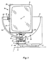
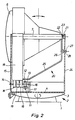
- a self-locking, horizontally rotatable rocker 2 is arranged on a support plate 1 mounted within a housing (not shown) of a video game device, the rocker plate 3 of which is firmly connected to the bottom 4 of a housing-like frame 5 for receiving a rectangular display tube 6.
- the rocker 2 is aligned in the direction of the axis 7 of the display tube 6, so that the inclination of the display tube 6 to the vertical can be changed.
- the rocker plate 3 of the rocker 2 can be rotated with difficulty, as a result of which the display tube 6 can also be rotated horizontally.
- a drive motor 8 on the bottom 4 of the same, the shaft 9 of which is additionally held in a bearing 10 arranged on the bottom 4.
- a pinion 11 which meshes with a toothed wheel 12, sits on the shaft 9 in a rotationally fixed manner.
- This gear wheel 12 is seated in a rotationally fixed manner on a shaft 13 running at right angles to the shaft 9 of the drive motor 8.
- One bearing 14 of the shaft 13 is in the front wall 15 of the frame 5 and the other bearing 16 of the shaft 13 is in one on the bottom 4 of the frame 5 arranged support 17 added. Between the front wall 15 of the frame 5 and the gear 12, the shaft 13 rotatably carries three adjacent drive wheels 18 of the same diameter.
- a quarter-circular support 19 is supported with its outside, from the ends of which a multi-angled holder 20 extends, which extends over the depth of the display tube 6.
- a stationary bearing 21 lying in the axis of rotation 7 of the display tube 6 rotatably receives the end of the holder 20 opposite the carrier 19.
- a bearing pin 23 is fastened to the web 22 of the holder 20 which runs parallel to the rear of the display tube 6 and is inserted into the bearing 21 arranged on the inside of the rear wall 24 of the frame 5 is.
- the web 25 extending from the web 22 and not in the axis of rotation 7 of the display tube 6 to the carrier 19 has a section 26 which runs parallel to the rear wall 24 of the frame 5 and which carries a pin 27 projecting in the direction of the rear wall 24.
- This pin 27 engages in an elongated hole 28 formed in the shape of a quarter circle in the rear wall 24.
- the ends of the elongated hole 28 serve as stops for the pin 27 to limit the 90 ° pivoting of the holder 20 and thus of the carrier 19th
- each cranked end of the angle bracket 31 receives a holding bracket 33 which is angled at the end via an appropriately designed screw connection 32.
- Each retaining tab 33 forms with the associated part of the angle tab 31 a support tab 34 for receiving the corresponding edge area of the display tube 6, i.e. the support tabs 34 enclose two mutually adjacent different edge lengths of the display tube 6 and thus hold the display tube 6 immovably.
- the drive wheels 18 transmit their rotational force to the quarter-circular support 19, and the display tube 6 thus carries out a pivoting movement through an angle of 90 °, so that the display tube 6 moves its position from a high ( Fig. 1) in a landscape format (Fig. 3) or vice versa.
- This requires only a relatively small free space within the housing of the video game device.
Landscapes
- Engineering & Computer Science (AREA)
- Multimedia (AREA)
- General Engineering & Computer Science (AREA)
- Mechanical Engineering (AREA)
- Signal Processing (AREA)
- Slot Machines And Peripheral Devices (AREA)
- Display Devices Of Pinball Game Machines (AREA)
- Devices For Indicating Variable Information By Combining Individual Elements (AREA)
- Pinball Game Machines (AREA)
Description
- Die Erfindung bezieht sich auf ein Video-Spielgerät mit einer zur hoch- oder querformatigen Bilddarstellung um 90° verdrehbar gehalterten Bildschirmröhre, die durch eine Spieiplatine steuerbar ist, wobei die Bildschirmröhre in der Bildebene in einem verschwenkbaren Träger festgelegt ist, der sich außenseitig auf einer mit einem Antriebsmotor oder mit einem Handantrieb angetriebenen Treibrolle abstützt.
- Bei derartigen Video-Spielgeräten weist die Spielplatine die erforderlichen Informationen auf, damit ein bestimmtes Spiel auf der Bildschirmröhre wiedergegeben und ausgeführt werden kann. Hierbei sind einige Spiele, wie beispielsweise Raumfahrtspiele, im Hochformat darzustellen, während eine andere Gruppe von Spielen sich besser für eine Darstellung im Querformat der Bildschirmröhre eignet. Entweder müssen für jede Spielgruppe unterschiedliche Geräte verwendet werden oder ein Monteur muß die entsprechende Ausrichtung der Bildschirmröhre des Gerätes vornehmen. Um diesen Nachteil zu beseitigen, ist bereits aus der DE-A-35 33 443 ein Video-Spielgerät mit Münzeinwurf bekannt, das mit einer um 90° verdreh- oder verschwenkbar gehalterten und durch eine Spielplatine gesteuerten Bildschirmröhre ausgerüstet und mit einem Bedienelemente tragenden Bedienpult versehen ist, wobei die Bildschirmröhre über einen motorgetriebenen Drehantrieb verschwenkbar ist. Eine rohrförmige Halterung nimmt die Bildschirmröhre auf, an der die Bildschirmröhre an vier Punkten befestigt ist. Die Halterung ist rückseitig in einem an der Rückwand des Gehäuses des Video-Spielgerätes angebrachten Lager drehbar gelagert. Über einen ebenfalls an der Rückwand des Gehäuses angebrachten motorischen Antrieb kann die Halterung um 90° von einer zur anderen Lage verschwenkt werden. Anstelle der rohrförmigen Halterung kann auch eine spinnenförmige Halterung aus vier Rohren mit an den vorderen Enden angebrachten Vierecklaschen zur Aufnahme der Bildschirmröhre zur Anwendung kommen. In beiden Fällen muß aufgrund der Hebelwirkung der Bildschirmröhre auf die Lagerung der Halterung diese relativ groß und stabil ausgeführt sein, was mit einem besonderen konstruktiven Aufwand verbunden ist. Darüber hinaus bedingt die Halterung, da sie die Bildschirmröhre vollständig umgibt, einen verhältnismäßig großen Einbauraum.
- Des weiteren ist aus der EP-A-0 230 291 ein Video-Spielautomat mit einem Gehäuse bekannt, in dem sich eine Bedienungsarmatur, mindestens ein Lautsprecher und mindestens eine Bildröhre sowie eine elektronische und elektrische Schaltung und gegebenenfalls ein Münzautomat befinden. Die Bildröhre ist in ihrer Bildebene mittels eines ansteuerbaren Motors schwenkbar gelagert und läßt sich mit Hilfe des Motors entsprechend der einstellbaren Position eines Programmwahlschalters und dem damit ausgewählten Programm (Spiel) in die diesem Programm entsprechende Position schwenken. Hierzu ist die Bildröhre mit einem ringförmigen auf vier über den Umfang verteilten Rollen gelagerten Rahmen mittels einer auf den äußeren Rand des Rahmens einwirkbaren Andruckrolle des ansteuerbaren Getriebemotors drehbar ausgebildet. Da der ringförmige Rahmen zum einen den Bildschirm vollständig umgibt und zum anderen außenseitig auf vier Rollen drehbar gelagert ist, benötigt die Einrichtung zur Drehung des Bildschirms insgesamt viel Einbauraum.
- Ferner ist aus der EP-A-351 817 eine Vorrichtung mit einer zur hoch- oder querformatigen Bilddarstellung um 90° in einem Gehäuse verdrehbar gehalterten Bildschirmröhre bekannt, wobei die Bildschirmröhre in einem in Führungslagern verschwenkbaren Tragbügel gehalten ist. Der Tragbügel ist exzentrisch, d.h. mit verschiedenen Mittelpunkten ausgebildet. Hierbei ist der Abstand von der Drehachse der Bildschirmröhre zu dem Tragbügel an der längeren Seite verschieden von dem Abstand zwischen der Drehachse und dem Tragbügel an der kürzeren Seite der Bildschirmröhre. An der Rückseite der Bildschirmröhre ist in der Drehachse ein Zapfen befestigt, der eine Scheibe trägt, die sich auf einer mit einem Antriebsmotor verbundenen Treibrolle abstützt.
- Der Erfindung liegt die Aufgabe zugrunde, ein Video-Spielgerät der eigangs genannten Art zu schaffen, das in kompakter Bauweise eine Einstellung der rechteckförmigen Bildschirmröhre im Hoch- oder Querformat, den leichten Einsatz von Bildschirmröhren unterschiedlicher Größe und den richtigen Blickwinkel auf die Bildschirmröhre ermöglicht.
- Diese Aufgabe wird erfindungsgemäß dadurch gelöst, daß der Träger der Bildschirmröhre viertelkreisförmig ausgebildet und in seiner Neigung zur Vertikalen verstellbar und/oder horizontal verdrehbar ist.
- Durch diese Maßnahmen wird für die Einrichtung zur Verschwenkung der Bildschirmröhre innerhalb des Gehäuses des Video-Spielgerätes nur wenig Raum beansprucht, wodurch das Video-Spielgerät insgesamt kompakter ausgeführt werden kann. Darüber hinaus ermöglicht der viertelkreisförmige Träger die Aufnahme von Bildschirmröhren unterschiedlicher Größe, da er die Bildschirmröhre nur in einem Teilbereich umgibt. Die Verstellbarkeit bzw. Verdrehbarkeit des Trägers ermöglicht es, dem Spieler stets den richtigen Blickwinkel auf die Bildschirmröhre zu gewähren. Durch die Auswahl eines Spiels mittels eines Auswahlschalters erfolgt über eine Steuerung bei Verwendung eines Antriebsmotors automatisch die Einstellung einer zugehörigen Position der Bildschirmröhre im Hoch- oder Querformat, die durch das ausgewählte Spiel bedingt wird.
- Zur Erzielung einer einfachen Abstützung des Trägers in der horizontalen Ebene sind nach einer vorteilhaften Weiterbildung des Erfindungsgegenstandes die Enden des viertelkreisförmigen Trägers mit einer mehrfach abgewinkelten, sich über die Tiefe der Bildschirmröhre erstreckenden Halterung verbunden, die in einem ortsfesten, in der Drehachse der Bildschirmröhre liegenden Lager gelagert ist.
- Weiterhin ist bevorzugt vorgesehen, daß an von der Innenseite des Trägers abgehenden Stegen der Halterung jeweils eine endseitig abgewinkelte, sich über die zugehörige Kantenlänge der Bildschirmröhre erstreckende Traglasche befestigt ist. Hierdurch ergibt sich eine sichere Aufnahme der Bildschirmröhre innerhalb des Trägers. Zweckmäßigerweise ist die Aufnahmebreite der Traglaschen für die Bildschirmröhre veränderbar. Somit sind auf einfache Weise Bildschirmröhren unterschiedlicher Größe an dem Träger zu befestigen.
- Damit ein zuverlässiger Antrieb des Trägers gewährleistet ist, sind nach einer vorteilhaften Weiterbildung der Erfindung mehrere nebeneinanderliegende Treibrollen auf einer gemeinsamen Welle drehfest angeordnet, auf der ein Zahnrad sitzt, das in ein auf der Welle des Antriebsmotors befestigtes Ritzel eingreift.
- Nach einer weiteren vorteilhaften Ausgestaltung der Erfindung ist der die Bildschirmröhre aufnehmende Träger mit seiner Halterung und seiner Antriebseinheit in einem gehäuseartigen Gestell untergebracht. Hierdurch ist eine Vormontage der Einrichtung zur Verschwenkung der Bildschirmröhre möglich, die lediglich in das Gehäuse des Video-Spielgerätes einzusetzen ist. Bevorzugt trägt hierbei der parallel zu der Rückseite der Bildschirmröhre verlaufende Steg der Halterung einen in der Drehachse der Bildschirmröhre angeordneten Lagerzapfen, der in das an der Rückwand des Gestells angebrachte Lager eingreift.
- Zur Endpositionierung der Schwenkbewegung des Trägers ist nach einer Weiterbildung der Erfindung der parallel zu der Rückwand des Gestells verlaufende Abschnitt eines sich von dem Bereich des Lagers aus zu dem Träger erstreckenden Steges der Halterung mit einem vorstehenden Zapfen verbunden, der in ein entsprechend kreisbogenförmig ausgebildetes Langloch in der Rückwand eingreift, wobei die Enden des Langloches als Anschläge für den Zapfen zur Begrenzung der Schwenkbewegung der Bildschirmröhre dienen.
- Zur Realisierung einer einfachen Neigungsverstellung der Bildschirmröhre ist bei einer vorteilhaften Ausgestaltung des Erfindungsgegenstandes der Boden des Gestells auf einer in Richtung der Drehachse der Bildschirmröhre verlaufenden, selbsthemmenden Wippe befestigt. Zweckmäßigerweise ist hierbei die Wippe horizontal schwergängig verdrehbar. Dies gewährleistet eine einfache Horizontal-Verstellung der Bildschirmröhre.
- Der der Erfindung zugrundeliegende Gedanke wird in der nachfolgenden Beschreibung anhand eines Ausführungsbeispieles, das in der Zeichnung dargestellt ist, näher erläutert. Es zeigt:
- Fig. 1
- eine Vorderansicht einer um Ihre Achse verschwenkbaren Bildschirmröhre, die in ein nicht dargestelltes Video-Spielgerät eingesetzt ist,
- Fig. 2
- eine Seitenansicht der Darstellung nach Fig. 1,
- Fig. 3
- eine Ansicht der Darstellung nach Fig. 1, jedoch mit querformatiger Lage der Bildchirmröhre und
- Fig. 4
- eine Draufsicht auf die Darstellung nach Fig. 3, jedoch ohne Bildschirmröhre.
- Auf einer innerhalb eines nicht darstellten Gehäuses eines Video-spielgerätes angebrachten Stützplatte 1 ist eine selbsthemmende, horizontal verdrehbare Wippe 2 angeordnet, deren Wipp-Platte 3 fest mit dem Boden 4 eines gehäuseartigen Gestells 5 für die Aufnahme einer rechteckförmigen Bildschirmröhre 6 verbunden ist. Die Wippe 2 ist in Richtung der Achse 7 der Bildschirmröhre 6 ausgerichtet, so daß die Bildschirmröhre 6 in ihrer Neigung zur Vertikalen veränderbar ist. Die Wipp-Platte 3 der Wippe 2 ist schwergängig verdrehbar, wodurch die Bildschirmröhre 6 ebenfalls horizontal verdrehbar ist.
- Im Innern des Gestells 5 befindet sich auf dem Boden 4 desselben ein Antriebsmotor 8, dessen Welle 9 zusätzlich in einem auf dem Boden 4 angeordneten Lager 10 gehaltert ist. Auf der Welle 9 sitzt drehfest ein Ritzel 11, das mit einem Zahnrad 12 kämmt. Dieses Zahnrad 12 sitzt drehfest auf einer rechtwinklig zu der Welle 9 des Antriebsmotors 8 verlaufenden Welle 13. Das eine Lager 14 der Welle 13 ist in der Vorderwand 15 des Gestells 5 und das andere Lager 16 der Welle 13 in einer auf dem Boden 4 des Gestells 5 angeordneten Stütze 17 aufgenommen. Zwischen der Vorderwand 15 des Gestells 5 und dem Zahnrad 12 trägt die Welle 13 drehfest drei nebeneinanderliegende Treibräder 18 gleichen Durchmessers. Auf den Treibrädern 18 stützt sich mit seiner Außenseite ein viertelkreisförmiger Träger 19 ab, von dessen Enden eine mehrfach abgewinkelte, sich über die Tiefe der Bildschirmröhre 6 erstreckende Halterung 20 abgeht. Ein in der Drehachse 7 der Bildschirmröhre 6 liegendes, ortsfestes Lager 21 nimmt das dem Träger 19 gegenüberliegende Ende der Halterung 20 drehbar auf. Hierzu ist an dem parallel zu der Rückseite der Bildschirmröhre 6 verlaufenden Steg 22 der Halterung 20 ein Lagerzapfen 23 befestigt, der in das an der Innenseite der Rückwand 24 des Gestells 5 angeordnete Lager 21 eingesetzt ist. Der von dem Steg 22 abgehende, nicht in der Drehachse 7 der Bildschirmröhre 6 liegende Steg 25 zu dem Träger 19 weist einen parallel zu der Rückwand 24 des Gestells 5 verlaufenden Abschnitt 26 auf, der einen in Richtung der Rückwand 24 vorstehenden Zapfen 27 trägt. Dieser Zapfen 27 greift in ein entsprechend viertelkreisbogenförmig ausgebildetes Langloch 28 in der Rückwand 24 ein. Die Enden des Langloches 28 dienen als Anschläge für den Zapfen 27 zur Begrenzung der 90°-Verschwenkung der Halterung 20 und damit des Trägers 19.
- Von den Enden des viertelkreisförmigen Trägers 19 gehen auf dessen Innenseite zwei rechtwinklig zueinander verlaufende Stege 29, 30 der Halterung 20 ab, an denen eine Winkellasche 31 mit ihren abgekröpften Enden befestigt ist, wobei die Abwinklung der Winkellasche 31 an der Innenseite des Trägers 19 anliegt. Jedes abgekröpfte Ende der Winkellasche 31 nimmt über eine entsprechend ausgebildete Schraubverbindung 32 längenverstellbar eine endseitig abgewinkelte Haltelasche 33 auf. Jede Haltelasche 33 bildet mit dem zugehörigen Teil der Winkellasche 31 eine Traglasche 34 für die Aufnahme des entsprechenden Kantenbereiches der Bildschirmröhre 6, d.h. die Traglaschen 34 schließen zwei aneinander angrenzende unterschiedliche Kantenlängen der Bildschirmröhre 6 ein und halten somit die Bildschirmröhre 6 unverrückbar fest.
- Sobald der Antriebsmotor 8 mit einer Spannung beaufschlagt wird, übertragen die Treibräder 18 ihre Drehkraft auf den viertelkreisförmigen Träger 19, und die Bildschirmröhre 6 führt somit eine Schwenkbewegung um einen Winkel von 90° aus, so daß die Bildschirmröhre 6 ihre Position von einem Hoch- (Fig. 1) in ein Querformat (Fig. 3) oder umgekehrt ändert. Hierfür wird nur ein verhältnismäßig kleiner Freiraum innerhalb des Gehäuses des Video-Spielgerätes benötigt.
- Die vorstehende Zeichnungsbeschreibung hat die besonders einfache und praktisch zu handhabende Konstruktion der Einrichtung zur Verschwenkung der Bildschirmröhre eines Video-Spielgerätes, die sich unbeschadet ihrer Einfachheit und Kompaktheit gleichwohl als äußerst zuverlässig erweist, in ihren Einzelheiten verdeutlicht. Obwohl die Erfindung nur an einem Ausführungsbeispiel beschrieben wurde, ergeben sich für den Fachmann naheliegende Abwandlungen der erfindungsgemäßen Lösung, die sich aus dieser Darstellung ergeben, jedoch im Rahmen der Ansprüche liegen.
Claims (10)
- Video-Spielgerät mit einer zur hoch- oder querformatigen Bilddarstellung um 90° verdrehbar gehalterten Bildschirmröhre (6), die durch eine Spielplatine steuerbar ist, wobei die Bildschirmröhre (6) in der Bildebene in einem verschwenkbaren Träger (19) festgelegt ist, der sich außenseitig auf einer mit einem Antriebsmotor (8) oder mit einem Handantrieb angetriebenen Treibrolle (18) abstützt, dadurch gekennzeichnet, daß der Träger (19) der Bildschirmröhre (6) viertelkreisförmig ausgebildet und in seiner Neigung zur Vertikalen verstellbar und/oder horizontal verdrehbar ist.
- Video-Spielgerät nach Anspruch 1, dadurch gekennzeichnet, daß die Enden des viertelkreisförmigen Trägers (19) mit einer mehrfach abgewinkelten, sich über die Tiefe der Bildschirmröhre (6) erstreckenden Halterung (20) verbunden sind, die in einem ortsfesten, in der Drehachse (7) der Bildschirmröhre (6) liegenden Lager (21) gelagert ist.
- Video-Spielgerät nach den Ansprüchen 1 und 2, dadurch gekennzeichnet, daß an von der Innenseite des Trägers (19) abgehenden Stegen (29, 30) der Halterung (20) jeweils eine endseitig abgewinkelte, sich über die zugehörige Kantenlänge der Bildschirmröhre (6) erstreckende Traglasche (34) befestigt ist.
- Video-Spielgerät nach Anspruch 3, dadurch gekennzeichnet, daß die Aufnahmebreite der Traglaschen (34) für die Bildschirmröhre (6) veränderbar ist.
- Video-Spielgerät nach einem der Ansprüche 1 bis 4, dadurch gekennzeichnet, daß mehrere nebeneinanderliegende Treibrollen (18) auf einer gemeinsamen Welle (13) drehfest angeordnet sind, auf der ein Zahnrad (12) sitzt, das in ein auf der Welle des Antriebsmotors (8) befestigtes Ritzel (11) eingreift.
- Video-Spielgerät nach einem der Ansprüche 1 bis 5, dadurch gekennzeichnet, daß der die Bildschirmröhre (6) aufnehmende Träger (19) mit seiner Halterung (20) und seiner Antriebseinheit in einem gehäuseartigen Gestell (5) untergebracht ist.
- Video-Spielgerät nach einem der Ansprüche 1 bis 6, dadurch gekennzeichnet, daß der parallel zu der Rückseite der Bildschirmröhre (6) verlaufende Steg (26) der Halterung (20) einen in der Drehachse (7) der Bildschirmröhre (6) angeordneten Lagerzapfen (23) trägt, der in das an der Rückwand (24) des Gestells (5) angebrachte Lager (21) eingreift.
- Video-Spielgerät nach einem der Ansprüche 1 bis 7, dadurch gekennzeichnet, daß der parallel zu der Rückwand (24) des Gestells (5) verlaufende Abschnitt (26) eines sich von dem Bereich des Lagers (21) aus zu dem Träger (19) erstreckenden Steges (25) der Halterung (20) mit einem vorstehenden Zapfen (27) verbunden ist, der in ein entsprechend kreisbogenförmig ausgebildetes Langloch (28) in der Rückwand (24) eingreift, wobei die Enden des Langloches (28) als Anschläge für den Zapfen (27) zur Begrenzung der Schwenkbewegung der Bildschirmröhre (6) dienen.
- Video-Spielgerät nach einem der Ansprüche 1 bis 8, dadurch gekennzeichnet, daß der Boden (4) des Gestells (5) auf einer in Richtung der Drehachse (7) der Bildschirmröhre (6) verlaufenden, selbsthemmenden Wippe (2) befestigt ist.
- Video-Spielgerät nach Anspruch 9, dadurch gekennzeichnet, daß die Wippe (2) horizontal schwergängig verdrehbar ist.
Applications Claiming Priority (2)
| Application Number | Priority Date | Filing Date | Title |
|---|---|---|---|
| DE4138638 | 1991-11-25 | ||
| DE4138638A DE4138638A1 (de) | 1991-11-25 | 1991-11-25 | Video-spielgeraet |
Publications (2)
| Publication Number | Publication Date |
|---|---|
| EP0544155A1 EP0544155A1 (de) | 1993-06-02 |
| EP0544155B1 true EP0544155B1 (de) | 1996-12-27 |
Family
ID=6445486
Family Applications (1)
| Application Number | Title | Priority Date | Filing Date |
|---|---|---|---|
| EP92119370A Expired - Lifetime EP0544155B1 (de) | 1991-11-25 | 1992-11-12 | Schwenkbare Bildschirmröhre für Video-Spielgeräte |
Country Status (3)
| Country | Link |
|---|---|
| EP (1) | EP0544155B1 (de) |
| AT (1) | ATE146686T1 (de) |
| DE (2) | DE4138638A1 (de) |
Cited By (3)
| Publication number | Priority date | Publication date | Assignee | Title |
|---|---|---|---|---|
| CN108799764A (zh) * | 2018-05-25 | 2018-11-13 | 郑州国知网络技术有限公司 | 一种信息技术用展示装置 |
| US11263865B2 (en) | 2019-06-07 | 2022-03-01 | Aristocrat Technologies, Inc. (ATI) | Electronic gaming machine having a variable position gaming display and a flexible gaming display responsive to gaming conditions |
| USD965687S1 (en) | 2019-05-10 | 2022-10-04 | Aristocrat Technologies Australia Pty Limited | Gaming machine |
Families Citing this family (5)
| Publication number | Priority date | Publication date | Assignee | Title |
|---|---|---|---|---|
| AU706976B2 (en) * | 1995-04-18 | 1999-07-01 | Precise Craft Pty Ltd. | Improvements to display screens for gaming machines |
| NO306280B1 (no) * | 1997-07-08 | 1999-10-11 | Stein R Foss | Versatil fjernsyns- eller dataskjerm |
| GB2380884A (en) * | 2001-10-10 | 2003-04-16 | Chuntex Electronic Co Ltd | Stand unit for a flat panel display |
| DE202008000841U1 (de) | 2008-01-21 | 2009-06-04 | Novomatic Ag | Spiel- und/oder Unterhaltungsgerät |
| CN114063326B (zh) * | 2021-09-08 | 2024-04-02 | 湖北顺通光电科技有限公司 | 一种lcd及lcm自动光学检测装置 |
Family Cites Families (4)
| Publication number | Priority date | Publication date | Assignee | Title |
|---|---|---|---|---|
| GB2076249A (en) * | 1980-05-16 | 1981-11-25 | Wells Theodor Wiehelm | Rockable TV mount |
| DE3309367A1 (de) * | 1983-03-16 | 1984-09-20 | Stan Peter 8700 Würzburg Dabrowski | Elektronisches muenzbetaetigtes tv-spielgeraet fuer universellen einsatz von computerspielprogrammen |
| DE3601813A1 (de) * | 1986-01-22 | 1987-07-23 | Eduard Steininger | Videoautomat |
| JP2612044B2 (ja) * | 1988-07-21 | 1997-05-21 | 株式会社日立製作所 | 電子ファイル装置 |
-
1991
- 1991-11-25 DE DE4138638A patent/DE4138638A1/de not_active Withdrawn
-
1992
- 1992-11-12 EP EP92119370A patent/EP0544155B1/de not_active Expired - Lifetime
- 1992-11-12 DE DE59207766T patent/DE59207766D1/de not_active Expired - Fee Related
- 1992-11-12 AT AT92119370T patent/ATE146686T1/de active
Cited By (6)
| Publication number | Priority date | Publication date | Assignee | Title |
|---|---|---|---|---|
| CN108799764A (zh) * | 2018-05-25 | 2018-11-13 | 郑州国知网络技术有限公司 | 一种信息技术用展示装置 |
| USD965687S1 (en) | 2019-05-10 | 2022-10-04 | Aristocrat Technologies Australia Pty Limited | Gaming machine |
| USD1079814S1 (en) | 2019-05-10 | 2025-06-17 | Aristocrat Technologies Australia Pty Limited | Bank of gaming machines |
| US11263865B2 (en) | 2019-06-07 | 2022-03-01 | Aristocrat Technologies, Inc. (ATI) | Electronic gaming machine having a variable position gaming display and a flexible gaming display responsive to gaming conditions |
| US11688231B2 (en) | 2019-06-07 | 2023-06-27 | Aristocrat Technologies, Inc. (ATI) | Electronic gaming machine having a variable position gaming display and a flexible gaming display responsive to gaming conditions |
| US12243378B2 (en) | 2019-06-07 | 2025-03-04 | Aristocrat Technologies, Inc. | Electronic gaming machine having a variable position gaming display and a flexible gaming display responsive to gaming conditions |
Also Published As
| Publication number | Publication date |
|---|---|
| EP0544155A1 (de) | 1993-06-02 |
| ATE146686T1 (de) | 1997-01-15 |
| DE4138638A1 (de) | 1993-05-27 |
| DE59207766D1 (de) | 1997-02-06 |
Similar Documents
| Publication | Publication Date | Title |
|---|---|---|
| DE10054912C2 (de) | Kühlschrank mit einer als Flüssigkristall ausgebildeten LCD-Anzeige | |
| DE3612640C2 (de) | ||
| DE4421056C2 (de) | Scharniereinrichtung | |
| EP0544155B1 (de) | Schwenkbare Bildschirmröhre für Video-Spielgeräte | |
| DE102008012884A1 (de) | Vorrichtung zum Verstellen der Position eines Bildschirms | |
| EP3193315A1 (de) | Kassensystem mit schwenkbaren armen | |
| DE112005003008T5 (de) | Anzeigeaufnahmevorrichtung | |
| DE10235807B4 (de) | Stützvorrichtung für einen Monitor | |
| DE3342741A1 (de) | Bildschirmgeraet mit einem schwenkbaren bildschirmgehaeuse | |
| LU602545B1 (de) | Eine Vergleichsvorrichtung für den Medizinausbildungsunterricht | |
| DE2230290C3 (de) | Abstunmvorrichtung für einen UHF-Tuner | |
| EP2307649B1 (de) | Antriebseinrichtung für ein schiebetor und verfahren zu deren montage | |
| DE2549261A1 (de) | Vergnuegungskarussell | |
| DE3533443A1 (de) | Videospielgeraet | |
| DE8614113U1 (de) | Vorrichtung zum Aufziehen von schlauchförmigen Hüllen auf ein Rohr, insbesondere das Füllrohr einer Wurstfüllmaschine | |
| DE3519997A1 (de) | Positionsanzeigesystem fuer eine motorkomponente | |
| CH684737A5 (de) | Stativ für einen Röntgenapparat. | |
| DE3719560A1 (de) | Positioniereinrichtung | |
| DE10041335A1 (de) | Froschklemme | |
| AT203238B (de) | Elektromotorischer Antrieb mit veränderbarer Drehzahl für Kleingeräte, insbesondere Magnettongeräte und Plattenspieler | |
| DE4400860C1 (de) | Büro- oder Arbeitstisch | |
| DE2529704A1 (de) | Antriebsvorrichtung fuer ein wechselverkehrszeichen o.dgl. | |
| DE3712795A1 (de) | Vorrichtung zum aufziehen von schlauchfoermigen huellen auf ein rohr, insbesondere das fuellrohr einer wurstfuellmaschine | |
| DE4430891A1 (de) | Zweiteiliger Antennenmast für Parabolspiegel mit Einstellmöglichkeit und Fixiermöglichkeit auf verschiedene Satelliten | |
| DE20307790U1 (de) | Seitenbügel für ein Untergestell einer Tisch- oder Arbeitsplatte |
Legal Events
| Date | Code | Title | Description |
|---|---|---|---|
| PUAI | Public reference made under article 153(3) epc to a published international application that has entered the european phase |
Free format text: ORIGINAL CODE: 0009012 |
|
| AK | Designated contracting states |
Kind code of ref document: A1 Designated state(s): AT CH DE FR GB IT LI |
|
| 17P | Request for examination filed |
Effective date: 19931119 |
|
| 17Q | First examination report despatched |
Effective date: 19940923 |
|
| GRAG | Despatch of communication of intention to grant |
Free format text: ORIGINAL CODE: EPIDOS AGRA |
|
| GRAH | Despatch of communication of intention to grant a patent |
Free format text: ORIGINAL CODE: EPIDOS IGRA |
|
| GRAH | Despatch of communication of intention to grant a patent |
Free format text: ORIGINAL CODE: EPIDOS IGRA |
|
| GRAA | (expected) grant |
Free format text: ORIGINAL CODE: 0009210 |
|
| AK | Designated contracting states |
Kind code of ref document: B1 Designated state(s): AT CH DE FR GB IT LI |
|
| REF | Corresponds to: |
Ref document number: 146686 Country of ref document: AT Date of ref document: 19970115 Kind code of ref document: T |
|
| REF | Corresponds to: |
Ref document number: 59207766 Country of ref document: DE Date of ref document: 19970206 |
|
| ITF | It: translation for a ep patent filed | ||
| GBT | Gb: translation of ep patent filed (gb section 77(6)(a)/1977) |
Effective date: 19970327 |
|
| ET | Fr: translation filed | ||
| PLBE | No opposition filed within time limit |
Free format text: ORIGINAL CODE: 0009261 |
|
| STAA | Information on the status of an ep patent application or granted ep patent |
Free format text: STATUS: NO OPPOSITION FILED WITHIN TIME LIMIT |
|
| PG25 | Lapsed in a contracting state [announced via postgrant information from national office to epo] |
Ref country code: AT Free format text: LAPSE BECAUSE OF NON-PAYMENT OF DUE FEES Effective date: 19971112 |
|
| PG25 | Lapsed in a contracting state [announced via postgrant information from national office to epo] |
Ref country code: LI Free format text: LAPSE BECAUSE OF NON-PAYMENT OF DUE FEES Effective date: 19971130 Ref country code: CH Free format text: LAPSE BECAUSE OF NON-PAYMENT OF DUE FEES Effective date: 19971130 |
|
| 26N | No opposition filed | ||
| REG | Reference to a national code |
Ref country code: CH Ref legal event code: PL |
|
| PGFP | Annual fee paid to national office [announced via postgrant information from national office to epo] |
Ref country code: GB Payment date: 19981014 Year of fee payment: 7 |
|
| PGFP | Annual fee paid to national office [announced via postgrant information from national office to epo] |
Ref country code: FR Payment date: 19981016 Year of fee payment: 7 |
|
| PGFP | Annual fee paid to national office [announced via postgrant information from national office to epo] |
Ref country code: DE Payment date: 19981214 Year of fee payment: 7 |
|
| PG25 | Lapsed in a contracting state [announced via postgrant information from national office to epo] |
Ref country code: GB Free format text: LAPSE BECAUSE OF NON-PAYMENT OF DUE FEES Effective date: 19991112 |
|
| GBPC | Gb: european patent ceased through non-payment of renewal fee |
Effective date: 19991112 |
|
| PG25 | Lapsed in a contracting state [announced via postgrant information from national office to epo] |
Ref country code: FR Free format text: LAPSE BECAUSE OF NON-PAYMENT OF DUE FEES Effective date: 20000731 |
|
| PG25 | Lapsed in a contracting state [announced via postgrant information from national office to epo] |
Ref country code: DE Free format text: LAPSE BECAUSE OF NON-PAYMENT OF DUE FEES Effective date: 20000901 |
|
| REG | Reference to a national code |
Ref country code: FR Ref legal event code: ST |
|
| PG25 | Lapsed in a contracting state [announced via postgrant information from national office to epo] |
Ref country code: IT Free format text: LAPSE BECAUSE OF NON-PAYMENT OF DUE FEES;WARNING: LAPSES OF ITALIAN PATENTS WITH EFFECTIVE DATE BEFORE 2007 MAY HAVE OCCURRED AT ANY TIME BEFORE 2007. THE CORRECT EFFECTIVE DATE MAY BE DIFFERENT FROM THE ONE RECORDED. Effective date: 20051112 |