EP0544155B1 - Moniteur cathodique pivotable pour appareils de jeux vidéo - Google Patents
Moniteur cathodique pivotable pour appareils de jeux vidéo Download PDFInfo
- Publication number
- EP0544155B1 EP0544155B1 EP92119370A EP92119370A EP0544155B1 EP 0544155 B1 EP0544155 B1 EP 0544155B1 EP 92119370 A EP92119370 A EP 92119370A EP 92119370 A EP92119370 A EP 92119370A EP 0544155 B1 EP0544155 B1 EP 0544155B1
- Authority
- EP
- European Patent Office
- Prior art keywords
- monitor tube
- gaming machine
- machine according
- video gaming
- tube
- Prior art date
- Legal status (The legal status is an assumption and is not a legal conclusion. Google has not performed a legal analysis and makes no representation as to the accuracy of the status listed.)
- Expired - Lifetime
Links
Images


Classifications
-
- A—HUMAN NECESSITIES
- A63—SPORTS; GAMES; AMUSEMENTS
- A63F—CARD, BOARD, OR ROULETTE GAMES; INDOOR GAMES USING SMALL MOVING PLAYING BODIES; VIDEO GAMES; GAMES NOT OTHERWISE PROVIDED FOR
- A63F13/00—Video games, i.e. games using an electronically generated display having two or more dimensions
- A63F13/60—Generating or modifying game content before or while executing the game program, e.g. authoring tools specially adapted for game development or game-integrated level editor
- A63F13/65—Generating or modifying game content before or while executing the game program, e.g. authoring tools specially adapted for game development or game-integrated level editor automatically by game devices or servers from real world data, e.g. measurement in live racing competition
- A63F13/655—Generating or modifying game content before or while executing the game program, e.g. authoring tools specially adapted for game development or game-integrated level editor automatically by game devices or servers from real world data, e.g. measurement in live racing competition by importing photos, e.g. of the player
-
- A—HUMAN NECESSITIES
- A63—SPORTS; GAMES; AMUSEMENTS
- A63F—CARD, BOARD, OR ROULETTE GAMES; INDOOR GAMES USING SMALL MOVING PLAYING BODIES; VIDEO GAMES; GAMES NOT OTHERWISE PROVIDED FOR
- A63F13/00—Video games, i.e. games using an electronically generated display having two or more dimensions
- A63F13/90—Constructional details or arrangements of video game devices not provided for in groups A63F13/20 or A63F13/25, e.g. housing, wiring, connections or cabinets
-
- A—HUMAN NECESSITIES
- A63—SPORTS; GAMES; AMUSEMENTS
- A63F—CARD, BOARD, OR ROULETTE GAMES; INDOOR GAMES USING SMALL MOVING PLAYING BODIES; VIDEO GAMES; GAMES NOT OTHERWISE PROVIDED FOR
- A63F13/00—Video games, i.e. games using an electronically generated display having two or more dimensions
- A63F13/25—Output arrangements for video game devices
-
- A—HUMAN NECESSITIES
- A63—SPORTS; GAMES; AMUSEMENTS
- A63F—CARD, BOARD, OR ROULETTE GAMES; INDOOR GAMES USING SMALL MOVING PLAYING BODIES; VIDEO GAMES; GAMES NOT OTHERWISE PROVIDED FOR
- A63F13/00—Video games, i.e. games using an electronically generated display having two or more dimensions
- A63F13/80—Special adaptations for executing a specific game genre or game mode
- A63F13/803—Driving vehicles or craft, e.g. cars, airplanes, ships, robots or tanks
-
- F—MECHANICAL ENGINEERING; LIGHTING; HEATING; WEAPONS; BLASTING
- F16—ENGINEERING ELEMENTS AND UNITS; GENERAL MEASURES FOR PRODUCING AND MAINTAINING EFFECTIVE FUNCTIONING OF MACHINES OR INSTALLATIONS; THERMAL INSULATION IN GENERAL
- F16M—FRAMES, CASINGS OR BEDS OF ENGINES, MACHINES OR APPARATUS, NOT SPECIFIC TO ENGINES, MACHINES OR APPARATUS PROVIDED FOR ELSEWHERE; STANDS; SUPPORTS
- F16M11/00—Stands or trestles as supports for apparatus or articles placed thereon ; Stands for scientific apparatus such as gravitational force meters
- F16M11/02—Heads
- F16M11/04—Means for attachment of apparatus; Means allowing adjustment of the apparatus relatively to the stand
- F16M11/06—Means for attachment of apparatus; Means allowing adjustment of the apparatus relatively to the stand allowing pivoting
- F16M11/10—Means for attachment of apparatus; Means allowing adjustment of the apparatus relatively to the stand allowing pivoting around a horizontal axis
- F16M11/105—Means for attachment of apparatus; Means allowing adjustment of the apparatus relatively to the stand allowing pivoting around a horizontal axis the horizontal axis being the roll axis, e.g. for creating a landscape-portrait rotation
-
- F—MECHANICAL ENGINEERING; LIGHTING; HEATING; WEAPONS; BLASTING
- F16—ENGINEERING ELEMENTS AND UNITS; GENERAL MEASURES FOR PRODUCING AND MAINTAINING EFFECTIVE FUNCTIONING OF MACHINES OR INSTALLATIONS; THERMAL INSULATION IN GENERAL
- F16M—FRAMES, CASINGS OR BEDS OF ENGINES, MACHINES OR APPARATUS, NOT SPECIFIC TO ENGINES, MACHINES OR APPARATUS PROVIDED FOR ELSEWHERE; STANDS; SUPPORTS
- F16M11/00—Stands or trestles as supports for apparatus or articles placed thereon ; Stands for scientific apparatus such as gravitational force meters
- F16M11/02—Heads
- F16M11/18—Heads with mechanism for moving the apparatus relatively to the stand
-
- F—MECHANICAL ENGINEERING; LIGHTING; HEATING; WEAPONS; BLASTING
- F16—ENGINEERING ELEMENTS AND UNITS; GENERAL MEASURES FOR PRODUCING AND MAINTAINING EFFECTIVE FUNCTIONING OF MACHINES OR INSTALLATIONS; THERMAL INSULATION IN GENERAL
- F16M—FRAMES, CASINGS OR BEDS OF ENGINES, MACHINES OR APPARATUS, NOT SPECIFIC TO ENGINES, MACHINES OR APPARATUS PROVIDED FOR ELSEWHERE; STANDS; SUPPORTS
- F16M11/00—Stands or trestles as supports for apparatus or articles placed thereon ; Stands for scientific apparatus such as gravitational force meters
- F16M11/20—Undercarriages with or without wheels
- F16M11/2007—Undercarriages with or without wheels comprising means allowing pivoting adjustment
- F16M11/2035—Undercarriages with or without wheels comprising means allowing pivoting adjustment in more than one direction
- F16M11/2064—Undercarriages with or without wheels comprising means allowing pivoting adjustment in more than one direction for tilting and panning
-
- H—ELECTRICITY
- H04—ELECTRIC COMMUNICATION TECHNIQUE
- H04N—PICTORIAL COMMUNICATION, e.g. TELEVISION
- H04N5/00—Details of television systems
- H04N5/64—Constructional details of receivers, e.g. cabinets or dust covers
- H04N5/645—Mounting of picture tube on chassis or in housing
-
- A—HUMAN NECESSITIES
- A63—SPORTS; GAMES; AMUSEMENTS
- A63F—CARD, BOARD, OR ROULETTE GAMES; INDOOR GAMES USING SMALL MOVING PLAYING BODIES; VIDEO GAMES; GAMES NOT OTHERWISE PROVIDED FOR
- A63F2300/00—Features of games using an electronically generated display having two or more dimensions, e.g. on a television screen, showing representations related to the game
- A63F2300/30—Features of games using an electronically generated display having two or more dimensions, e.g. on a television screen, showing representations related to the game characterized by output arrangements for receiving control signals generated by the game device
Definitions
- the invention relates to a video game device with a screen tube which is rotatable by 90 ° for portrait or landscape image display and which can be controlled by a game board, the screen tube being fixed in the image plane in a pivotable carrier which is on the outside on one with a drive motor or with a manually driven drive roller.
- the game board has the necessary information so that a particular game can be played and executed on the display tube.
- some games such as space games, are to be displayed in portrait format, while another group of games is better suited for display in landscape format of the display tube.
- Either different devices have to be used for each play group or a technician has to adjust the screen tube of the device accordingly.
- a video game device with coin insertion is already known from DE-A-35 33 443, which is equipped with and equipped with a screen tube which is rotated or pivoted through 90 ° and controlled by a game board a control panel carrying control elements is provided, the screen tube being pivotable via a motor-driven rotary drive.
- a tubular holder holds the display tube, to which the display tube is attached at four points.
- the holder is rotatably mounted on the rear in a bearing attached to the rear wall of the housing of the video game device.
- the bracket can be swiveled 90 ° from one position to the other by means of a motor drive also attached to the rear wall of the housing.
- a spider-shaped holder made of four tubes with square tabs attached to the front ends can also be used to hold the display tube.
- due to the leverage effect of the display tube on the mounting of the holder it must be made relatively large and stable, which is associated with a special design effort.
- the bracket since the bracket completely surrounds the display tube, it requires a relatively large installation space.
- a video game machine with a housing is known from EP-A-0 230 291, in which an operating armature, at least one loudspeaker and at least one picture tube as well as an electronic and electrical circuit and optionally a coin operated machine are located.
- the picture tube is pivotally mounted in its image plane by means of a controllable motor and can be pivoted into the position corresponding to this program with the aid of the motor in accordance with the adjustable position of a program selector switch and the program (play) selected therewith.
- the picture tube is designed to be rotatable with an annular frame mounted on four rollers distributed over the circumference by means of a pressure roller of the controllable geared motor which can act on the outer edge of the frame. Since the ring-shaped frame on the one hand completely surrounds the screen and on the other hand is rotatably mounted on the outside on four rollers, the device for rotating the screen requires a total of installation space.
- EP-A-351 817 is a device with a display tube which is rotatably rotated through 90 ° in a housing for portrait or landscape image display, the display tube being held in a support bracket which can be pivoted in guide bearings.
- the bracket is eccentric, i.e. trained with different centers.
- the distance from the axis of rotation of the display tube to the support bracket on the longer side is different from the distance between the axis of rotation and the support bracket on the shorter side of the display tube.
- a pin is attached in the axis of rotation, which carries a disc which is supported on a drive roller connected to a drive motor.
- the invention has for its object to provide a video game device of the type mentioned above, which enables the rectangular display tube to be adjusted in portrait or landscape format, the easy use of display tubes of different sizes and the correct viewing angle on the display tube in a compact design.
- this object is achieved in that the support of the display tube is quarter-circle-shaped and its inclination to the vertical can be adjusted and / or rotated horizontally.
- the quarter-circular support allows the inclusion of screen tubes of different sizes, since it surrounds the screen tube only in a partial area.
- the adjustability or rotatability of the carrier allows the player to always have the correct viewing angle on the screen tube.
- the ends of the quarter-circular support are connected to a multi-angled holder which extends over the depth of the display tube and which is in a fixed position in the axis of rotation of the display tube lying bearing is stored.
- a strap which is angled at the end and extends over the associated edge length of the display tube is fastened to webs of the holder which depart from the inside of the carrier. This results in a secure reception of the display tube within the carrier.
- the width of the support straps for the display tube can expediently be changed. Screen tubes of different sizes can thus be attached to the support in a simple manner.
- a plurality of adjacent drive rollers are arranged in a rotationally fixed manner on a common shaft on which a gearwheel sits which engages in a pinion fastened on the shaft of the drive motor.
- the support receiving the display tube is accommodated with its holder and its drive unit in a housing-like frame. This makes it possible to preassemble the device for pivoting the display tube, which is only to be inserted into the housing of the video game device.
- the web of the holder running parallel to the rear of the display tube preferably carries a bearing pin arranged in the axis of rotation of the display tube, which engages in the bearing attached to the rear wall of the frame.
- the section running parallel to the rear wall of the frame is one of the area of the bearing from the web of the bracket extending to the support is connected to a projecting pin which engages in a correspondingly circular-shaped elongated hole in the rear wall, the ends of the elongated hole serving as stops for the pin to limit the pivoting movement of the display tube.
- the base of the frame is attached to a self-locking rocker running in the direction of the axis of rotation of the display tube.
- the rocker can expediently be rotated here so that it is difficult to move horizontally. This ensures easy horizontal adjustment of the display tube.
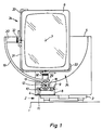
- a self-locking, horizontally rotatable rocker 2 is arranged on a support plate 1 mounted within a housing (not shown) of a video game device, the rocker plate 3 of which is firmly connected to the bottom 4 of a housing-like frame 5 for receiving a rectangular display tube 6.
- the rocker 2 is aligned in the direction of the axis 7 of the display tube 6, so that the inclination of the display tube 6 to the vertical can be changed.
- the rocker plate 3 of the rocker 2 can be rotated with difficulty, as a result of which the display tube 6 can also be rotated horizontally.
- a drive motor 8 on the bottom 4 of the same, the shaft 9 of which is additionally held in a bearing 10 arranged on the bottom 4.
- a pinion 11 which meshes with a toothed wheel 12, sits on the shaft 9 in a rotationally fixed manner.
- This gear wheel 12 is seated in a rotationally fixed manner on a shaft 13 running at right angles to the shaft 9 of the drive motor 8.
- One bearing 14 of the shaft 13 is in the front wall 15 of the frame 5 and the other bearing 16 of the shaft 13 is in one on the bottom 4 of the frame 5 arranged support 17 added. Between the front wall 15 of the frame 5 and the gear 12, the shaft 13 rotatably carries three adjacent drive wheels 18 of the same diameter.
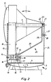
- a quarter-circular support 19 is supported with its outside, from the ends of which a multi-angled holder 20 extends, which extends over the depth of the display tube 6.
- a stationary bearing 21 lying in the axis of rotation 7 of the display tube 6 rotatably receives the end of the holder 20 opposite the carrier 19.
- a bearing pin 23 is fastened to the web 22 of the holder 20 which runs parallel to the rear of the display tube 6 and is inserted into the bearing 21 arranged on the inside of the rear wall 24 of the frame 5 is.
- the web 25 extending from the web 22 and not in the axis of rotation 7 of the display tube 6 to the carrier 19 has a section 26 which runs parallel to the rear wall 24 of the frame 5 and which carries a pin 27 projecting in the direction of the rear wall 24.
- This pin 27 engages in an elongated hole 28 formed in the shape of a quarter circle in the rear wall 24.
- the ends of the elongated hole 28 serve as stops for the pin 27 to limit the 90 ° pivoting of the holder 20 and thus of the carrier 19th
- each cranked end of the angle bracket 31 receives a holding bracket 33 which is angled at the end via an appropriately designed screw connection 32.
- Each retaining tab 33 forms with the associated part of the angle tab 31 a support tab 34 for receiving the corresponding edge area of the display tube 6, i.e. the support tabs 34 enclose two mutually adjacent different edge lengths of the display tube 6 and thus hold the display tube 6 immovably.
- the drive wheels 18 transmit their rotational force to the quarter-circular support 19, and the display tube 6 thus carries out a pivoting movement through an angle of 90 °, so that the display tube 6 moves its position from a high ( Fig. 1) in a landscape format (Fig. 3) or vice versa.
- This requires only a relatively small free space within the housing of the video game device.
Landscapes
- Engineering & Computer Science (AREA)
- Multimedia (AREA)
- General Engineering & Computer Science (AREA)
- Mechanical Engineering (AREA)
- Signal Processing (AREA)
- Slot Machines And Peripheral Devices (AREA)
- Display Devices Of Pinball Game Machines (AREA)
- Devices For Indicating Variable Information By Combining Individual Elements (AREA)
- Pinball Game Machines (AREA)
Claims (10)
- Appareil de jeu vidéo avec un tube cathodique (6) maintenu tournant de 90° pour la représentation d'images en format vertical ou transversal, qui est commandable au moyen d'une platine de jeu, le tube cathodique (6) étant fixé dans le plan de l'image dans un support pivotable (19), qui prend appui, sur le côté extérieur, sur un rouleau moteur (18) entraîné au moyen d'un moteur d'entraînement (8) ou d'un entraînement manuel, caractérisé en ce que le support (19) du tube cathodique (6) est en forme de quart de cercle et est réglable dans son inclinaison par rapport à la verticale et/ou peut tourner horizontalement.
- Appareil de jeu vidéo selon la revendication 1, caractérisé en ce que les extrémités du support (19) en forme de quart de cercle sont reliées à une fixation (20), coudée plusieurs fois, s'étendant sur la profondeur du tube cathodique (6), laquelle est montée dans un palier (21) fixe, se situant dans l'axe de rotation (7) du tube cathodique (6).
- Appareil de jeu vidéo selon les revendications 1 et 2, caractérisé en ce que sur chacune des entretoises (29, 30), partant du côté intérieur du support (19), de la fixation (20), est fixée une attache de support (34), coudée côté extrémité, s'étendant sur la longueur correspondante des bords du tube cathodique (6).
- Appareil de jeu vidéo selon la revendication 3, caractérisé en ce que la largeur de réception des attaches de support (34) pour le tube cathodique (6) est variable.
- Appareil de jeu vidéo selon l'une des revendications 1 à 4, caractérisé en ce que plusieurs rouleaux moteurs (18) juxtaposés sont placés solidairement en rotation sur un arbre (13) commun, sur lequel est calée une roue dentée (12), qui s'engrène avec un pignon (11) fixé sur l'arbre du moteur d'entraînement (8).
- Appareil de jeu vidéo selon l'une des revendications 1 à 5, caractérisé en ce que le support (19) recevant le tube cathodique (6) avec sa fixation (20) et son unité d'entraînement est logé dans un bâti (5) côté boîtier.
- Appareil de jeu vidéo selon l'une des revendications 1 à 6, caractérisé en ce que l'entretoise (26), s'étendant parallèlement à la face arrière du tube cathodique (6), de la fixation (20), porte un tourillon (23), placé dans l'axe de rotation (7) du tube cathodique (6), qui s'engage dans le palier (21), placé sur la paroi arrière (24) du bâti (5).
- Appareil de jeu vidéo selon l'une des revendications 1 à 7, caractérisé en ce que la portion (26), s'étendant parallèlement à la paroi arrière (24) du bâti (5), d'une entretoise (25), s'étendant à partir de la zone du palier (21) vers le support (19), de la fixation (20), est reliée à un téton (27) saillant, qui s'engage dans un trou oblong (28), conformé en correspondance en arc de cercle, dans la paroi arrière (24), les extrémités du trou oblong (28) servant de butées au téton (27) pour limiter le mouvement de pivotement du tube cathodique (6).
- Appareil de jeu vidéo selon l'une des revendications 1 à 8, caractérisé en ce que le fond (4) du bâti (5) est fixé sur une bascule (2) autobloquante, s'étendant dans la direction de l'axe de rotation (7) du tube cathodique (6).
- Appareil de jeu vidéo selon la revendication 9, caractérisé en ce que la bascule (2) peut difficilement tourner horizontalement.
Applications Claiming Priority (2)
| Application Number | Priority Date | Filing Date | Title |
|---|---|---|---|
| DE4138638 | 1991-11-25 | ||
| DE4138638A DE4138638A1 (de) | 1991-11-25 | 1991-11-25 | Video-spielgeraet |
Publications (2)
| Publication Number | Publication Date |
|---|---|
| EP0544155A1 EP0544155A1 (fr) | 1993-06-02 |
| EP0544155B1 true EP0544155B1 (fr) | 1996-12-27 |
Family
ID=6445486
Family Applications (1)
| Application Number | Title | Priority Date | Filing Date |
|---|---|---|---|
| EP92119370A Expired - Lifetime EP0544155B1 (fr) | 1991-11-25 | 1992-11-12 | Moniteur cathodique pivotable pour appareils de jeux vidéo |
Country Status (3)
| Country | Link |
|---|---|
| EP (1) | EP0544155B1 (fr) |
| AT (1) | ATE146686T1 (fr) |
| DE (2) | DE4138638A1 (fr) |
Cited By (3)
| Publication number | Priority date | Publication date | Assignee | Title |
|---|---|---|---|---|
| CN108799764A (zh) * | 2018-05-25 | 2018-11-13 | 郑州国知网络技术有限公司 | 一种信息技术用展示装置 |
| US11263865B2 (en) | 2019-06-07 | 2022-03-01 | Aristocrat Technologies, Inc. (ATI) | Electronic gaming machine having a variable position gaming display and a flexible gaming display responsive to gaming conditions |
| USD965687S1 (en) | 2019-05-10 | 2022-10-04 | Aristocrat Technologies Australia Pty Limited | Gaming machine |
Families Citing this family (5)
| Publication number | Priority date | Publication date | Assignee | Title |
|---|---|---|---|---|
| AU706976B2 (en) * | 1995-04-18 | 1999-07-01 | Precise Craft Pty Ltd. | Improvements to display screens for gaming machines |
| NO306280B1 (no) * | 1997-07-08 | 1999-10-11 | Stein R Foss | Versatil fjernsyns- eller dataskjerm |
| GB2380884A (en) * | 2001-10-10 | 2003-04-16 | Chuntex Electronic Co Ltd | Stand unit for a flat panel display |
| DE202008000841U1 (de) | 2008-01-21 | 2009-06-04 | Novomatic Ag | Spiel- und/oder Unterhaltungsgerät |
| CN114063326B (zh) * | 2021-09-08 | 2024-04-02 | 湖北顺通光电科技有限公司 | 一种lcd及lcm自动光学检测装置 |
Family Cites Families (4)
| Publication number | Priority date | Publication date | Assignee | Title |
|---|---|---|---|---|
| GB2076249A (en) * | 1980-05-16 | 1981-11-25 | Wells Theodor Wiehelm | Rockable TV mount |
| DE3309367A1 (de) * | 1983-03-16 | 1984-09-20 | Stan Peter 8700 Würzburg Dabrowski | Elektronisches muenzbetaetigtes tv-spielgeraet fuer universellen einsatz von computerspielprogrammen |
| DE3601813A1 (de) * | 1986-01-22 | 1987-07-23 | Eduard Steininger | Videoautomat |
| JP2612044B2 (ja) * | 1988-07-21 | 1997-05-21 | 株式会社日立製作所 | 電子ファイル装置 |
-
1991
- 1991-11-25 DE DE4138638A patent/DE4138638A1/de not_active Withdrawn
-
1992
- 1992-11-12 EP EP92119370A patent/EP0544155B1/fr not_active Expired - Lifetime
- 1992-11-12 DE DE59207766T patent/DE59207766D1/de not_active Expired - Fee Related
- 1992-11-12 AT AT92119370T patent/ATE146686T1/de active
Cited By (6)
| Publication number | Priority date | Publication date | Assignee | Title |
|---|---|---|---|---|
| CN108799764A (zh) * | 2018-05-25 | 2018-11-13 | 郑州国知网络技术有限公司 | 一种信息技术用展示装置 |
| USD965687S1 (en) | 2019-05-10 | 2022-10-04 | Aristocrat Technologies Australia Pty Limited | Gaming machine |
| USD1079814S1 (en) | 2019-05-10 | 2025-06-17 | Aristocrat Technologies Australia Pty Limited | Bank of gaming machines |
| US11263865B2 (en) | 2019-06-07 | 2022-03-01 | Aristocrat Technologies, Inc. (ATI) | Electronic gaming machine having a variable position gaming display and a flexible gaming display responsive to gaming conditions |
| US11688231B2 (en) | 2019-06-07 | 2023-06-27 | Aristocrat Technologies, Inc. (ATI) | Electronic gaming machine having a variable position gaming display and a flexible gaming display responsive to gaming conditions |
| US12243378B2 (en) | 2019-06-07 | 2025-03-04 | Aristocrat Technologies, Inc. | Electronic gaming machine having a variable position gaming display and a flexible gaming display responsive to gaming conditions |
Also Published As
| Publication number | Publication date |
|---|---|
| EP0544155A1 (fr) | 1993-06-02 |
| ATE146686T1 (de) | 1997-01-15 |
| DE4138638A1 (de) | 1993-05-27 |
| DE59207766D1 (de) | 1997-02-06 |
Similar Documents
| Publication | Publication Date | Title |
|---|---|---|
| DE10054912C2 (de) | Kühlschrank mit einer als Flüssigkristall ausgebildeten LCD-Anzeige | |
| DE3612640C2 (fr) | ||
| DE4421056C2 (de) | Scharniereinrichtung | |
| EP0544155B1 (fr) | Moniteur cathodique pivotable pour appareils de jeux vidéo | |
| DE102008012884A1 (de) | Vorrichtung zum Verstellen der Position eines Bildschirms | |
| EP3193315A1 (fr) | Systeme de caisses comprenant des bras pivotants | |
| DE112005003008T5 (de) | Anzeigeaufnahmevorrichtung | |
| DE10235807B4 (de) | Stützvorrichtung für einen Monitor | |
| DE3342741A1 (de) | Bildschirmgeraet mit einem schwenkbaren bildschirmgehaeuse | |
| LU602545B1 (de) | Eine Vergleichsvorrichtung für den Medizinausbildungsunterricht | |
| DE2230290C3 (de) | Abstunmvorrichtung für einen UHF-Tuner | |
| EP2307649B1 (fr) | Dispositif d'entraînement pour un portail coulissant et son procédé de montage | |
| DE2549261A1 (de) | Vergnuegungskarussell | |
| DE3533443A1 (de) | Videospielgeraet | |
| DE8614113U1 (de) | Vorrichtung zum Aufziehen von schlauchförmigen Hüllen auf ein Rohr, insbesondere das Füllrohr einer Wurstfüllmaschine | |
| DE3519997A1 (de) | Positionsanzeigesystem fuer eine motorkomponente | |
| CH684737A5 (de) | Stativ für einen Röntgenapparat. | |
| DE3719560A1 (de) | Positioniereinrichtung | |
| DE10041335A1 (de) | Froschklemme | |
| AT203238B (de) | Elektromotorischer Antrieb mit veränderbarer Drehzahl für Kleingeräte, insbesondere Magnettongeräte und Plattenspieler | |
| DE4400860C1 (de) | Büro- oder Arbeitstisch | |
| DE2529704A1 (de) | Antriebsvorrichtung fuer ein wechselverkehrszeichen o.dgl. | |
| DE3712795A1 (de) | Vorrichtung zum aufziehen von schlauchfoermigen huellen auf ein rohr, insbesondere das fuellrohr einer wurstfuellmaschine | |
| DE4430891A1 (de) | Zweiteiliger Antennenmast für Parabolspiegel mit Einstellmöglichkeit und Fixiermöglichkeit auf verschiedene Satelliten | |
| DE20307790U1 (de) | Seitenbügel für ein Untergestell einer Tisch- oder Arbeitsplatte |
Legal Events
| Date | Code | Title | Description |
|---|---|---|---|
| PUAI | Public reference made under article 153(3) epc to a published international application that has entered the european phase |
Free format text: ORIGINAL CODE: 0009012 |
|
| AK | Designated contracting states |
Kind code of ref document: A1 Designated state(s): AT CH DE FR GB IT LI |
|
| 17P | Request for examination filed |
Effective date: 19931119 |
|
| 17Q | First examination report despatched |
Effective date: 19940923 |
|
| GRAG | Despatch of communication of intention to grant |
Free format text: ORIGINAL CODE: EPIDOS AGRA |
|
| GRAH | Despatch of communication of intention to grant a patent |
Free format text: ORIGINAL CODE: EPIDOS IGRA |
|
| GRAH | Despatch of communication of intention to grant a patent |
Free format text: ORIGINAL CODE: EPIDOS IGRA |
|
| GRAA | (expected) grant |
Free format text: ORIGINAL CODE: 0009210 |
|
| AK | Designated contracting states |
Kind code of ref document: B1 Designated state(s): AT CH DE FR GB IT LI |
|
| REF | Corresponds to: |
Ref document number: 146686 Country of ref document: AT Date of ref document: 19970115 Kind code of ref document: T |
|
| REF | Corresponds to: |
Ref document number: 59207766 Country of ref document: DE Date of ref document: 19970206 |
|
| ITF | It: translation for a ep patent filed | ||
| GBT | Gb: translation of ep patent filed (gb section 77(6)(a)/1977) |
Effective date: 19970327 |
|
| ET | Fr: translation filed | ||
| PLBE | No opposition filed within time limit |
Free format text: ORIGINAL CODE: 0009261 |
|
| STAA | Information on the status of an ep patent application or granted ep patent |
Free format text: STATUS: NO OPPOSITION FILED WITHIN TIME LIMIT |
|
| PG25 | Lapsed in a contracting state [announced via postgrant information from national office to epo] |
Ref country code: AT Free format text: LAPSE BECAUSE OF NON-PAYMENT OF DUE FEES Effective date: 19971112 |
|
| PG25 | Lapsed in a contracting state [announced via postgrant information from national office to epo] |
Ref country code: LI Free format text: LAPSE BECAUSE OF NON-PAYMENT OF DUE FEES Effective date: 19971130 Ref country code: CH Free format text: LAPSE BECAUSE OF NON-PAYMENT OF DUE FEES Effective date: 19971130 |
|
| 26N | No opposition filed | ||
| REG | Reference to a national code |
Ref country code: CH Ref legal event code: PL |
|
| PGFP | Annual fee paid to national office [announced via postgrant information from national office to epo] |
Ref country code: GB Payment date: 19981014 Year of fee payment: 7 |
|
| PGFP | Annual fee paid to national office [announced via postgrant information from national office to epo] |
Ref country code: FR Payment date: 19981016 Year of fee payment: 7 |
|
| PGFP | Annual fee paid to national office [announced via postgrant information from national office to epo] |
Ref country code: DE Payment date: 19981214 Year of fee payment: 7 |
|
| PG25 | Lapsed in a contracting state [announced via postgrant information from national office to epo] |
Ref country code: GB Free format text: LAPSE BECAUSE OF NON-PAYMENT OF DUE FEES Effective date: 19991112 |
|
| GBPC | Gb: european patent ceased through non-payment of renewal fee |
Effective date: 19991112 |
|
| PG25 | Lapsed in a contracting state [announced via postgrant information from national office to epo] |
Ref country code: FR Free format text: LAPSE BECAUSE OF NON-PAYMENT OF DUE FEES Effective date: 20000731 |
|
| PG25 | Lapsed in a contracting state [announced via postgrant information from national office to epo] |
Ref country code: DE Free format text: LAPSE BECAUSE OF NON-PAYMENT OF DUE FEES Effective date: 20000901 |
|
| REG | Reference to a national code |
Ref country code: FR Ref legal event code: ST |
|
| PG25 | Lapsed in a contracting state [announced via postgrant information from national office to epo] |
Ref country code: IT Free format text: LAPSE BECAUSE OF NON-PAYMENT OF DUE FEES;WARNING: LAPSES OF ITALIAN PATENTS WITH EFFECTIVE DATE BEFORE 2007 MAY HAVE OCCURRED AT ANY TIME BEFORE 2007. THE CORRECT EFFECTIVE DATE MAY BE DIFFERENT FROM THE ONE RECORDED. Effective date: 20051112 |