EP0545178A1 - Papiertransportapparat - Google Patents
Papiertransportapparat Download PDFInfo
- Publication number
- EP0545178A1 EP0545178A1 EP92119813A EP92119813A EP0545178A1 EP 0545178 A1 EP0545178 A1 EP 0545178A1 EP 92119813 A EP92119813 A EP 92119813A EP 92119813 A EP92119813 A EP 92119813A EP 0545178 A1 EP0545178 A1 EP 0545178A1
- Authority
- EP
- European Patent Office
- Prior art keywords
- guide plate
- guide
- plate
- paper conveying
- support plate
- Prior art date
- Legal status (The legal status is an assumption and is not a legal conclusion. Google has not performed a legal analysis and makes no representation as to the accuracy of the status listed.)
- Granted
Links
- 230000007246 mechanism Effects 0.000 description 7
- 230000003287 optical effect Effects 0.000 description 4
- 238000012986 modification Methods 0.000 description 2
- 230000004048 modification Effects 0.000 description 2
- 238000004140 cleaning Methods 0.000 description 1
- 238000003780 insertion Methods 0.000 description 1
- 230000037431 insertion Effects 0.000 description 1
Images


Classifications
-
- B—PERFORMING OPERATIONS; TRANSPORTING
- B65—CONVEYING; PACKING; STORING; HANDLING THIN OR FILAMENTARY MATERIAL
- B65H—HANDLING THIN OR FILAMENTARY MATERIAL, e.g. SHEETS, WEBS, CABLES
- B65H5/00—Feeding articles separated from piles; Feeding articles to machines
- B65H5/06—Feeding articles separated from piles; Feeding articles to machines by rollers or balls, e.g. between rollers
- B65H5/062—Feeding articles separated from piles; Feeding articles to machines by rollers or balls, e.g. between rollers between rollers or balls
Definitions
- the present invention relates to a paper conveying apparatus of the type that can be used in copying machines, printers, paper sorters, and the like.
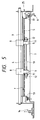
- a conventional paper conveying apparatus which can be used in an image forming apparatus or the like will be described with reference to Fig. 5.
- a first guide plate 3 is mounted on a paper feeding deck body 25 so as to extend along the paper conveying direction.
- the openable/closable support plate 7 has one end pivotally connected to the body 25 by a hinge 6 and the other end can be locked to the body 25 by lock mechanisms 14.
- Rotationally driven conveying rollers 8 and follower rollers 9 are arranged opposite to and in contact with each other. Paper sandwiched between conveying rollers 8 and follower rollers 9 is carried in the paper conveying path 4.
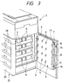
- the support plate 7 is integrated with an openable/closable door 45 provided on the side portion of the body 25 as shown in Fig. 3.
- the follower rollers 9 are urged towards the conveying rollers 8.
- bearings 11 for supporting a support shaft 10 of the follower rollers 9 are elastically-supported on the second guide plate 5 by springs 12 so as to be urged toward the conveying rollers 8.
- the second guide plate 5 is elastically supported at opposite ends by springs 13 on the support plate 7 so as to be urged toward the first guide plate 3.
- the springs 12 for urging the follower rollers 9 and the springs 13 for urging the second guide plate 5 impose opposing urging forces on the second guide plate 5. That is, when the urging force of the springs 12 urges the follower rollers 9 against the conveying rollers 8, the second guide plate 5 is pushed against the urging force of the springs 13 and is moved to a position indicated by the dotted chain line. Thus, the predetermined space t can not be maintained between the first guide plate 3 and the second guide plate 5. Accordingly, the paper can not be carried suitably.
- An object of the present invention is to provide a paper conveying apparatus having an openable/closable support plate that can be easily opened and closed.
- the present invention provides a paper conveying apparatus having a first guide plate secured in the paper conveying direction and a second guide plate proximate thereto.
- a paper conveying path is formed as a predetermined space between the second guide plate and the first guide plate.
- the second guide plate is elastically supported on an openable/closable support plate and is urged toward the first guide plate to sandwich paper between rotationally driven conveying rollers and follower rollers.
- the follower rollers and conveying rollers are arranged opposite to and in contact with each other.
- the follower rollers are elastically supported on the openable/closable support plate and are urged toward the conveying rollers in the paper conveying path to enable the rollers to forward the paper within the paper conveying path.
- the spring force for urging the follower rollers against the conveying rollers and the spring force for urging the second guide plate operate independently of each other. Therefore, the spring force being exerted on the second guide plate can be independently selected without considering the spring force on the conveying rollers. Accordingly, it is possible that the spring force being exerted on the second guide plate is relatively weaker than in the conventional apparatus thus allowing the hooking force for locking the support plate to be less than in the conventional apparatus. Hence, the support plate can be opened and closed easily.
- FIG. 1 is a plan view showing a main portion of an embodiment of the paper conveying apparatus according to the present invention.
- FIG. 2 is a side view taken along the direction of arrows II-II in FIG. 1.
- FIG. 3 is a perspective view showing a support plate of the paper conveying apparatus cooperating with an electrostatic photography copying machine.
- FIG. 4 is a cut away side view showing the configuration of the entire electrostatic photography copying machine.
- FIG. 5 is a plan view showing a main portion of a conventional paper conveying apparatus.
- Fig. 4 shows the configuration view of an electrostatic photography copying machine provided with the paper conveying apparatus 1 according to the present invention.
- a deck body 25 of the paper feeding deck 21 a plurality of front loading type paper feeding cassettes 28 are horizontally mounted in stages. Paper feeding rollers 23 are provided above the front portions of the paper feeding cassettes 28, respectively.
- the paper conveying apparatus 1 further has a vertical paper conveying path 4 formed between opposing guide plates 3 and 5.
- a paper discharge outlet 29 is provided at the top end of the paper conveying path 4 and communicates with a curved conveying path 30 in the copying machine body 2.
- the curved conveying path 30 further communicates with a conveying path 31 which conveys paper to the center portion of the copying machine body 2.
- An image forming portion 32 for forming an image is provided at the center portion of the copying machine body 2 and an optical scanning system 33 is provided at the top portion of the copying machine body 2.
- An optical scanning system 33 is provided at the top portion of the copying machine body 2.
- a platen 34 covered with an openable/closable cover 35 is provided over the optical scanning system 33 at the upper surface of the copying machine body 2.
- the image forming portion 32 comprises a photosensitive drum 36, main charger 37, a developing device 38, a transferring charger 39, a separating charger 40, and a cleaning device 41, etc., which are disposed about the circumference of the photosensitive drum 36.
- a conveying belt 42 is provided to convey paper from the photosensitive drum 36 to a fixing device 43.
- Paper discharge rollers 44 are provided proximate to the fixing device 43 to discharge paper from the fixing device 43 to a paper discharge tray 46 attached to the exterior of the copying machine body 2.
- an operator places an item to be copied (e.g. document) on the platen 34.
- the operator enters the number of copies to be made through an operation panel (e.g. ten-key panel, not shown) provided on the outside of the copying machine and activates copying start button (not shown).
- the optical scanning system 33 detects the size of the item and the paper feeding rollers 23 feed the paper from the appropriate paper feeding cassette 28 into the paper conveying path 4.
- Paper fed from any of the paper feeding cassettes 28 by its corresponding paper feeding roller 23 passes a corresponding one of the smaller-diameter rollers 15, which contacts its corresponding one of the conveying rollers 8, and enters the paper conveying path 4.
- the paper entering the paper conveying path 4 abuts against the second guide plate 5, bends upward and is conveyed through the paper conveying path 4 by the conveying rollers 8 and the follower rollers 9 toward the paper discharge outlet 29.
- the paper passes through the paper discharge outlet 29 and enters the curved conveying path 30 in the copying machine body 2.
- the paper is fed from the curved conveying path 30, which communicates with the paper discharge outlet 29, to the conveying path 31.
- the paper is then conveyed through the conveying path 31 to the image forming portion 32 at the center portion of the copying machine body 2.
- the optical scanning system 33 exposes the item on the platen 34 to form an image on the photo-sensitive drum 36 and the image is transferred on the paper.
- the paper is separated from the drum and conveyed by the conveying belt 42 to the fixing device 43.
- the fixing device 43 grabs the paper and the paper discharge rollers 44 discharge the paper onto the paper discharge tray 46.
- first guide plates 3 are fixedly supported in the deck body 25 and are mounted in the vertical direction corresponding to the conveying direction of the paper.
- a second guide plate 5 is elastically supported on a support plate 7 which can be connected to the inner surface of a door 45 or integral with the door 45.
- the door 45 is openably/closably supported by the deck body 25 by hinges 6 and is locked in a closed position by lock mechanisms 14.
- the paper conveying path 4 having a predetermined space t is formed between each of the first guide plates 3 and the second guide plate 5 which is elastically supported on the support plate 7.
- One end of the support plate 7 is pivotally coupled to the side plate 27 of the deck body 25 by hinges 6, while the other end of the support plate 7 is lock-hooked by the lock mechanisms 14 to the side plate 26 of the deck body 25.
- Reception portions 14a of the lock mechanisms 14 are attached to the side plate 26, and insertion portions 14b extending from the support plate 7 insert into the reception portions 14a to lock the support plate 7 and the door 45 (see Fig. 3) in the closed position.
- a handle (not shown) of the door 45 is pulled, the support plate 7 can be opened together with the door 45 as shown by a dotted chain line.
- the first guide plate 3 is secured at its opposite ends to side plates 26 and 27 of the deck body 25. In the position corresponding to each of the paper feeding cassettes 28, a pair of openings 3a are formed in the corresponding first guide plate 3, and the corresponding conveying rollers 8 are secured to driving shaft 17 so that the conveying rollers 8 partially project outwardly from the openings 3a into the paper conveying path 4.
- the driving shaft 17 is supported by a pair of bearings 16 secured to the side plates 26 and 27, respectively, and is rotated by a driving source (not shown).
- the second guide plate 5 has flange portions 5a and 5b bent outward at its opposite ends. Guide holes are formed in the flange portions 5a and 5b. Bolts 15 are implanted on the support plate 7 and project inward toward guide plates 3. The guide holes formed in the flange portions 5a and 5b of the second guide plate 5 each have a diameter slightly larger than that of the bolts 15. Thus, bolts 15 pass through guide holes 5a and 5b, respectively.
- Guide pieces 5c and 5d project from the flange portions 5a and 5b and are guided in the guide holes 3c and 3d formed in the first guide plates 3. Therefore, if the support plate 7 and/or door 45 slants relative to the deck body 25, the guide pieces 5c and 5d of the second guide plate 5 always correctly align the second guide plate 5 relative to the first guide plates 3. Accordingly, slant feeding of the paper can effectively be prevented.
- the small-diameter follower rollers 9 are elastically supported on the support plate 7 by springs 12 and oppose the large-diameter rotationally driven conveying rollers 8 when the support plate 7 is in the closed position.
- the springs 12 urge the follower rollers 9 toward the conveying rollers to contact the conveying rollers 8.
- the conveying rollers 8 are driven to rotate at fixed positions in the paper conveying paths 4.
- a pair of support brackets 18 are formed on the support plate 7 at its inner side and project inward toward the guide plates 3 when the support plate 7 is in the closed position.
- Bearings 11 for supporting the support shaft 10 of the follower rollers 9 are held by the springs 12 suspended between the opposite shoulder portions of the brackets 18.
- Guide brackets 19 for guiding the bearings 11 respectively are formed on the second guide plate 5 and project outward. Vertical grooves (not shown) in which inside edges of the guide brackets 19 are loosely inserted are formed in the bearings 11 at their front and rear sides, respectively.
- the springs 12 urge follower rollers 9 toward the conveying rollers 8 without being influenced by the forces exerted on the second guide plate 5 by springs 13. That is, the springs 12 for urging the follower rollers and the springs 13 for urging the second guide plate 5 do not interfere with each other.
- the respective spring forces of the springs 12 and 13 can be selected to have suitable values independently of each other. Accordingly, the spring force of the springs 13 for urging the second guide plate 5 can be selected to be a value relatively weaker than that in the conventional apparatus, and the hooking force of the lock mechanism 14 can be small thus allowing the door 45 to be locked and unlocked easily to facilitate opening and closing.
Landscapes
- Engineering & Computer Science (AREA)
- Mechanical Engineering (AREA)
- Delivering By Means Of Belts And Rollers (AREA)
- Feeding Of Articles By Means Other Than Belts Or Rollers (AREA)
- Paper Feeding For Electrophotography (AREA)
Applications Claiming Priority (2)
| Application Number | Priority Date | Filing Date | Title |
|---|---|---|---|
| JP341994/91 | 1991-11-30 | ||
| JP3341994A JP2649026B2 (ja) | 1991-11-30 | 1991-11-30 | 用紙搬送装置 |
Publications (2)
| Publication Number | Publication Date |
|---|---|
| EP0545178A1 true EP0545178A1 (de) | 1993-06-09 |
| EP0545178B1 EP0545178B1 (de) | 1995-02-22 |
Family
ID=18350356
Family Applications (1)
| Application Number | Title | Priority Date | Filing Date |
|---|---|---|---|
| EP92119813A Expired - Lifetime EP0545178B1 (de) | 1991-11-30 | 1992-11-20 | Papiertransportapparat |
Country Status (4)
| Country | Link |
|---|---|
| US (1) | US5265869A (de) |
| EP (1) | EP0545178B1 (de) |
| JP (1) | JP2649026B2 (de) |
| DE (1) | DE69201484T2 (de) |
Cited By (5)
| Publication number | Priority date | Publication date | Assignee | Title |
|---|---|---|---|---|
| EP0857673A3 (de) * | 1997-01-17 | 1998-08-19 | Seiko Epson Corporation | Rollenwalzenmechanismus zum Zu- und Abführen von Blättern |
| EP1249414A3 (de) * | 2001-04-12 | 2003-08-06 | FL Technology Inc. | Bankautomat |
| CN103373620A (zh) * | 2012-04-26 | 2013-10-30 | 佳能株式会社 | 片材输送设备和成像设备 |
| EP2386508A3 (de) * | 2010-05-12 | 2014-04-09 | Murata Machinery, Ltd. | Papiertransportvorrichtung, Papierzuführeinheit und Bilderzeugungsvorrichtung |
| CN112551213A (zh) * | 2020-11-17 | 2021-03-26 | 萍乡市时代工艺包装有限公司 | 一种数码印刷用物料输送装置 |
Families Citing this family (18)
| Publication number | Priority date | Publication date | Assignee | Title |
|---|---|---|---|---|
| US5499810A (en) * | 1993-12-14 | 1996-03-19 | Unisys Corporation | Pinch-roll with floating damper |
| US6386662B1 (en) * | 1997-02-03 | 2002-05-14 | Citicorp Development Center, Inc. | Wide mouth banking depositor |
| US6336629B1 (en) * | 1999-11-26 | 2002-01-08 | Xerox Corporation | Idler mounting tie-bar assembly |
| US6736395B2 (en) * | 2001-02-23 | 2004-05-18 | Ascom Hasler Mailing Systems, Inc. | Access to letter path |
| US6578845B2 (en) * | 2001-04-09 | 2003-06-17 | Mustek Systems Inc. | Automatic document feeding apparatus having separation mechanism |
| KR100485782B1 (ko) * | 2003-01-04 | 2005-04-28 | 삼성전자주식회사 | 화상형성장치의 용지배출장치 |
| US6857631B2 (en) * | 2003-07-15 | 2005-02-22 | Xerox Corporation | Printer sheet feeding path idler rollers biased mounting system |
| US6964414B2 (en) * | 2003-09-24 | 2005-11-15 | Xerox Corporation | Jam clearance in a vertical sheet transport in a printing apparatus |
| KR100815582B1 (ko) * | 2004-01-29 | 2008-03-20 | 삼성전자주식회사 | 용지 이송 장치 |
| JP5230268B2 (ja) * | 2008-05-28 | 2013-07-10 | キヤノン株式会社 | シート搬送装置及び画像形成装置 |
| JP5929502B2 (ja) * | 2012-05-22 | 2016-06-08 | 富士ゼロックス株式会社 | 給紙装置及び画像形成装置 |
| JP5801832B2 (ja) * | 2013-01-31 | 2015-10-28 | 株式会社沖データ | 媒体搬送装置及び画像形成装置 |
| JP5784057B2 (ja) * | 2013-03-19 | 2015-09-24 | 京セラドキュメントソリューションズ株式会社 | シート搬送装置、およびこれを備えたシート処理装置 |
| CN103449221B (zh) * | 2013-08-27 | 2016-06-22 | 昆山能缇精密电子有限公司 | 三料带送料机 |
| JP6282150B2 (ja) * | 2014-03-19 | 2018-02-21 | キヤノン株式会社 | シート搬送装置および画像形成装置 |
| JP6614772B2 (ja) * | 2014-12-25 | 2019-12-04 | キヤノン株式会社 | シート搬送装置及び画像形成装置 |
| JP6590959B2 (ja) * | 2018-01-22 | 2019-10-16 | キヤノン株式会社 | シート搬送装置および画像形成装置 |
| CN108928656B (zh) * | 2018-08-02 | 2019-10-25 | 合肥海闻自动化设备有限公司 | 一种纸板印刷驱动机构 |
Citations (1)
| Publication number | Priority date | Publication date | Assignee | Title |
|---|---|---|---|---|
| US5024431A (en) * | 1987-10-16 | 1991-06-18 | Minolta Camera Kabushiki Kaisha | Sheet transport device with easy sheet jam handling |
Family Cites Families (4)
| Publication number | Priority date | Publication date | Assignee | Title |
|---|---|---|---|---|
| US4431179A (en) * | 1982-02-16 | 1984-02-14 | Bell & Howell Company | Transport channel systems |
| JPS63139850A (ja) * | 1986-12-02 | 1988-06-11 | Minolta Camera Co Ltd | 記録装置 |
| JPH0829856B2 (ja) * | 1987-07-15 | 1996-03-27 | コニカ株式会社 | シ−ト搬送装置 |
| JPH0213041U (de) * | 1988-07-11 | 1990-01-26 |
-
1991
- 1991-11-30 JP JP3341994A patent/JP2649026B2/ja not_active Expired - Lifetime
-
1992
- 1992-11-20 EP EP92119813A patent/EP0545178B1/de not_active Expired - Lifetime
- 1992-11-20 DE DE69201484T patent/DE69201484T2/de not_active Expired - Lifetime
- 1992-11-30 US US07/983,225 patent/US5265869A/en not_active Expired - Lifetime
Patent Citations (1)
| Publication number | Priority date | Publication date | Assignee | Title |
|---|---|---|---|---|
| US5024431A (en) * | 1987-10-16 | 1991-06-18 | Minolta Camera Kabushiki Kaisha | Sheet transport device with easy sheet jam handling |
Cited By (9)
| Publication number | Priority date | Publication date | Assignee | Title |
|---|---|---|---|---|
| EP0857673A3 (de) * | 1997-01-17 | 1998-08-19 | Seiko Epson Corporation | Rollenwalzenmechanismus zum Zu- und Abführen von Blättern |
| US6032951A (en) * | 1997-01-17 | 2000-03-07 | Seiko Epson Corporation | Sheet feed/discharge roller mechanism |
| CN1083387C (zh) * | 1997-01-17 | 2002-04-24 | 精工爱普生株式会社 | 进纸/排纸辊机构 |
| EP1249414A3 (de) * | 2001-04-12 | 2003-08-06 | FL Technology Inc. | Bankautomat |
| EP2386508A3 (de) * | 2010-05-12 | 2014-04-09 | Murata Machinery, Ltd. | Papiertransportvorrichtung, Papierzuführeinheit und Bilderzeugungsvorrichtung |
| CN103373620A (zh) * | 2012-04-26 | 2013-10-30 | 佳能株式会社 | 片材输送设备和成像设备 |
| CN103373620B (zh) * | 2012-04-26 | 2016-08-31 | 佳能株式会社 | 片材输送设备和成像设备 |
| CN112551213A (zh) * | 2020-11-17 | 2021-03-26 | 萍乡市时代工艺包装有限公司 | 一种数码印刷用物料输送装置 |
| CN112551213B (zh) * | 2020-11-17 | 2023-04-07 | 萍乡市时代工艺包装有限公司 | 一种数码印刷用物料输送装置 |
Also Published As
| Publication number | Publication date |
|---|---|
| US5265869A (en) | 1993-11-30 |
| DE69201484D1 (de) | 1995-03-30 |
| DE69201484T2 (de) | 1995-07-27 |
| JP2649026B2 (ja) | 1997-09-03 |
| EP0545178B1 (de) | 1995-02-22 |
| JPH05155461A (ja) | 1993-06-22 |
Similar Documents
| Publication | Publication Date | Title |
|---|---|---|
| US5265869A (en) | Paper conveying apparatus having conveying rollers and independently supported follower rollers | |
| EP0353790B1 (de) | Elektrostatisches Kopiergerät | |
| KR950007526B1 (ko) | 화상 형성장치 | |
| EP1070995B1 (de) | Wiederzufuhrgerät und Bilderzeugungsgerät | |
| US6064498A (en) | Image forming apparatus | |
| EP0281097B1 (de) | Papierzuführungsvorrichtung | |
| US4900005A (en) | Sheet feed apparatus | |
| EP0407984B1 (de) | Automatische Fördervorrichtung für Dokumente | |
| EP1099986A1 (de) | Bilderzeugungsvorrichtung | |
| JP3427291B2 (ja) | 画像形成装置 | |
| US4545668A (en) | Image forming apparatus | |
| JP2005031377A (ja) | 画像形成装置 | |
| JPH04166956A (ja) | 画像形成装置 | |
| JPH08188344A (ja) | 画像形成装置及び両面用搬送装置 | |
| JP3396832B2 (ja) | 両面画像形成装置 | |
| JPH11288205A (ja) | 画像形成装置 | |
| JP2923948B2 (ja) | 画像形成装置 | |
| JP3373681B2 (ja) | 画像形成装置 | |
| JPS62201775A (ja) | 画像形成装置 | |
| JP2938145B2 (ja) | 複写機内蔵型デスク | |
| JPH07206199A (ja) | 給紙装置の重送防止機構 | |
| JPH0850438A (ja) | 画像形成装置 | |
| JP2004352380A (ja) | 用紙搬送装置 | |
| HK1011423B (en) | Resupplying apparatus and image forming apparatus | |
| JPH04260544A (ja) | 画像形成装置 |
Legal Events
| Date | Code | Title | Description |
|---|---|---|---|
| PUAI | Public reference made under article 153(3) epc to a published international application that has entered the european phase |
Free format text: ORIGINAL CODE: 0009012 |
|
| AK | Designated contracting states |
Kind code of ref document: A1 Designated state(s): DE FR GB IT |
|
| 17P | Request for examination filed |
Effective date: 19930714 |
|
| 17Q | First examination report despatched |
Effective date: 19930914 |
|
| GRAA | (expected) grant |
Free format text: ORIGINAL CODE: 0009210 |
|
| AK | Designated contracting states |
Kind code of ref document: B1 Designated state(s): DE FR GB IT |
|
| REF | Corresponds to: |
Ref document number: 69201484 Country of ref document: DE Date of ref document: 19950330 |
|
| ITF | It: translation for a ep patent filed | ||
| ET | Fr: translation filed | ||
| PLBE | No opposition filed within time limit |
Free format text: ORIGINAL CODE: 0009261 |
|
| STAA | Information on the status of an ep patent application or granted ep patent |
Free format text: STATUS: NO OPPOSITION FILED WITHIN TIME LIMIT |
|
| 26N | No opposition filed | ||
| REG | Reference to a national code |
Ref country code: GB Ref legal event code: IF02 |
|
| PGFP | Annual fee paid to national office [announced via postgrant information from national office to epo] |
Ref country code: FR Payment date: 20041109 Year of fee payment: 13 |
|
| PG25 | Lapsed in a contracting state [announced via postgrant information from national office to epo] |
Ref country code: IT Free format text: LAPSE BECAUSE OF NON-PAYMENT OF DUE FEES;WARNING: LAPSES OF ITALIAN PATENTS WITH EFFECTIVE DATE BEFORE 2007 MAY HAVE OCCURRED AT ANY TIME BEFORE 2007. THE CORRECT EFFECTIVE DATE MAY BE DIFFERENT FROM THE ONE RECORDED. Effective date: 20051120 |
|
| PG25 | Lapsed in a contracting state [announced via postgrant information from national office to epo] |
Ref country code: FR Free format text: LAPSE BECAUSE OF NON-PAYMENT OF DUE FEES Effective date: 20060731 |
|
| REG | Reference to a national code |
Ref country code: FR Ref legal event code: ST Effective date: 20060731 |
|
| PGFP | Annual fee paid to national office [announced via postgrant information from national office to epo] |
Ref country code: DE Payment date: 20101117 Year of fee payment: 19 |
|
| PGFP | Annual fee paid to national office [announced via postgrant information from national office to epo] |
Ref country code: GB Payment date: 20101117 Year of fee payment: 19 |
|
| GBPC | Gb: european patent ceased through non-payment of renewal fee |
Effective date: 20111120 |
|
| REG | Reference to a national code |
Ref country code: DE Ref legal event code: R119 Ref document number: 69201484 Country of ref document: DE Effective date: 20120601 |
|
| PG25 | Lapsed in a contracting state [announced via postgrant information from national office to epo] |
Ref country code: GB Free format text: LAPSE BECAUSE OF NON-PAYMENT OF DUE FEES Effective date: 20111120 |
|
| PG25 | Lapsed in a contracting state [announced via postgrant information from national office to epo] |
Ref country code: DE Free format text: LAPSE BECAUSE OF NON-PAYMENT OF DUE FEES Effective date: 20120601 |