EP0545529B1 - Connecteur électrique - Google Patents
Connecteur électrique Download PDFInfo
- Publication number
- EP0545529B1 EP0545529B1 EP92309195A EP92309195A EP0545529B1 EP 0545529 B1 EP0545529 B1 EP 0545529B1 EP 92309195 A EP92309195 A EP 92309195A EP 92309195 A EP92309195 A EP 92309195A EP 0545529 B1 EP0545529 B1 EP 0545529B1
- Authority
- EP
- European Patent Office
- Prior art keywords
- contact
- housing
- lances
- male
- tubular portion
- Prior art date
- Legal status (The legal status is an assumption and is not a legal conclusion. Google has not performed a legal analysis and makes no representation as to the accuracy of the status listed.)
- Expired - Lifetime
Links
Images


Classifications
-
- H—ELECTRICITY
- H01—ELECTRIC ELEMENTS
- H01R—ELECTRICALLY-CONDUCTIVE CONNECTIONS; STRUCTURAL ASSOCIATIONS OF A PLURALITY OF MUTUALLY-INSULATED ELECTRICAL CONNECTING ELEMENTS; COUPLING DEVICES; CURRENT COLLECTORS
- H01R13/00—Details of coupling devices of the kinds covered by groups H01R12/70 or H01R24/00 - H01R33/00
- H01R13/40—Securing contact members in or to a base or case; Insulating of contact members
- H01R13/42—Securing in a demountable manner
- H01R13/428—Securing in a demountable manner by resilient locking means on the contact members; by locking means on resilient contact members
Definitions
- This invention relates to an electric connector for the connection of an electric circuit, and more particularly to improvements in or relating to the structure of a housing of an electric connector.
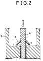
- FIG. 1 Various electric connectors are already known, and a partial view of an example of a conventional electric connector is shown in FIG. 1.
- the electric connector of the type shown is formed from a combination of an outer housing 1 having a male contact 4 and an inner housing 6 having a female contact 5.
- the inner housing 6 is fitted into the outer housing 1, whereby the male contact 4 in the outer housing 1 is force-fitted into the female contact 5 in the inner housing 6 to establish electric connection.
- Each contact 4, 5 of the male and female portions has a plurality of resilient lances 2, 7 extending laterally from the contacts, and after insertion of the male portion into the corresponding housing 1, 6, lances 2, 7 are expanded laterally in the internal spacing of each housing so as to prevent separation of the contacts 4, 5 from the housings 1, 6.
- Dimension a in FIG. 1 is defined as a dimension necessary to maintain good contact between the male and female contacts 4 and 5 after the inner housing 6 is inserted into the outer housing 1, causing the male contact 4 to fit into the female contact 5.
- Female contact may also be fixed within the inner housing by such means as soldering or by adhesive means rather than by lances.
- US-3957337 and DE-2320079 disclose oblique leaf springs or spring tongues, which project towards or into annular corners, but their inclinations are not considered. In fact the latter features axial grooves and freedoms of rotational movement.
- an electric connector comprises expansion limiting means provided on the supporting means for the lances around a portion of eacg housing in which the lances of each contact extend for the purpose of limiting excessive expansion of the lances.
- the expansion limiting means is a tubular portion making up part of the housing, the inner diameter of the tubular portion being equal to the sum of the outer diameter of each contact and a dimension of 1.4 times the length of the lances, and the outer diameter being sufficient for the expansion limiting means to reach the wall of the inner spacing of the housing.
- the tubular portion may be formed integrally with the housing or may be manufactured as a tubular member separate from the housing and securely mounted, when the housing is assembled, into the portion of the housing through which the lances of the contact extend.
- lateral expansion of the lances of the contact is limited to the inner diameter of the tubular portion, and also to an angular range of almost 45° with respect to the axial direction, and accordingly, the axial dimension necessary for the contact between the male and female contacts is assured and the reliability of the electric connection between the contacts is enhanced.
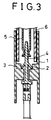
- FIG. 3 shows a partial view of the outer housing of a preferred embodiment of the present invention.
- the electric connector includes an outer housing 1 having a male contact 4 and an inner housing 6 having a female contact 5.
- the male contact 4 is inserted in the outer housing 1 and has a plurality of lances 2 extending laterally and expansible to a fixed angle due to the resiliency of the lances.
- the electric connector of the present invention is characterized in that a tubular portion 3 serving as expansion limiting means for limiting the expansion angle ⁇ of the lance 2 to within a predetermined angular range is additionally provided in the outer housing 1 as shown in FIG. 3.
- the tubular portion 3 is formed by integral molding with the outer housing 1 in such a manner as to project radially inwardly from the surface of the inner spacing of the outer housing 1.
- the tubular portion 3 may be formed from the same material as the outer housing 1 and adhered to the outer housing 1 before the male contact 4 is inserted into the outer housing 1. This makes it possible to apply the present invention to conventional electric connectors already manufactured.
- the inner diameter Di of the tubular portion 3 is equal to the dimension of the sum of the outer diameter Dc of the male contact 4 and a distance substantially equal to 1.4L.
- the length of 1.4L mentioned above signifies the length of 0.7L for each lance 2 and also signifies that the value of ⁇ defines an angle less than 45°, and accordingly, the force acting upon each lance 2 upon the axial movement of the male contact 4 has a component of force acting in the expanding direction, that is, in a radial direction from the axis of the male contact 4 which is smaller than the other component of force acting in the axial direction.
Landscapes
- Connector Housings Or Holding Contact Members (AREA)
Claims (2)
- Connecteur électrique comprenant un boîtier extérieur (1) ayant un contact mâle (4) lui étant fixé, et un boîtier intérieur (6) couplé de manière amovible au boîtier extérieur et ayant un contact femelle (5) qui est mis en contact avec le contact mâle, lorsque le contact mâle (4) est inséré dans le contact femelle (5), afin d'établir une connexion électrique, dans lequel :au moins un contact parmi les contacts mâle et femelle (4, 5), présente, à titre de moyen de fixation du contact à un boîtier (1, 6) correspondant, une pluralité de lances (2) qui s'étendent latéralement en raison de leur élasticité, chaque boîtier (1, 6) correspondant au contact (4, 5) ayant les lances (2) présente un moyen de support pour les lances (2) et un moyen de limitation d'expansion, prévu sur le moyen de support pour limiter l'expansion des lances,le moyen de limitation d'expansion comprend une partie tubulaire (3) prévue au fond du boîtier, à travers laquelle s'étend le contact; caractérisé en ce que la partie tubulaire (3) présente un diamètre intérieur (Di) égal à la somme du diamètre (Dc) du contact (4, 5) et d'une dimension égale à à peu près 1,4 fois la longueur (L) des lances (2), et d'un diamètre extérieur (Do) suffisant pour que le moyen de limitation d'expansion (3) atteigne la paroi du logement intérieur du boîtier (1, 6).
- Connecteur électrique selon la revendication 1, dans lequel la parie tubulaire est un organe tubulaire (3) formé séparément du boîtier (1, 6) et est montée rigidement dans le boîtier, lors de l'insertion du contact (4, 5) dans le boîtier.
Applications Claiming Priority (2)
| Application Number | Priority Date | Filing Date | Title |
|---|---|---|---|
| JP106742U JPH0548236U (ja) | 1991-11-30 | 1991-11-30 | コネクタ |
| JP106742/91 | 1991-11-30 |
Publications (3)
| Publication Number | Publication Date |
|---|---|
| EP0545529A2 EP0545529A2 (fr) | 1993-06-09 |
| EP0545529A3 EP0545529A3 (en) | 1993-08-18 |
| EP0545529B1 true EP0545529B1 (fr) | 1997-01-08 |
Family
ID=14441379
Family Applications (1)
| Application Number | Title | Priority Date | Filing Date |
|---|---|---|---|
| EP92309195A Expired - Lifetime EP0545529B1 (fr) | 1991-11-30 | 1992-10-08 | Connecteur électrique |
Country Status (4)
| Country | Link |
|---|---|
| US (1) | US5376023A (fr) |
| EP (1) | EP0545529B1 (fr) |
| JP (1) | JPH0548236U (fr) |
| DE (1) | DE69216566T2 (fr) |
Families Citing this family (4)
| Publication number | Priority date | Publication date | Assignee | Title |
|---|---|---|---|---|
| EP0654855B1 (fr) * | 1993-10-22 | 1998-05-27 | Molex Incorporated | Connecteur électrique avec moyens de rétention améliorés |
| KR0125926Y1 (ko) * | 1995-06-21 | 1998-10-01 | 구자홍 | 전자레인지의 히터터미널 탈거방지구조 |
| US6168478B1 (en) * | 1998-08-28 | 2001-01-02 | Lucent Technologies, Inc. | Snap type retention mechanism for connector terminals |
| JP4047705B2 (ja) * | 2002-11-18 | 2008-02-13 | 日本圧着端子製造株式会社 | スクイブのシャント |
Family Cites Families (5)
| Publication number | Priority date | Publication date | Assignee | Title |
|---|---|---|---|---|
| DE2320079A1 (de) * | 1973-04-19 | 1974-11-14 | Bunker Ramo | Steckverbinder |
| US3957337A (en) * | 1975-02-21 | 1976-05-18 | Litton Systems, Inc. | Miniature electrical connector having contact centering means |
| DE2830620A1 (de) * | 1978-07-12 | 1980-01-24 | Bunker Ramo | Kontaktelement |
| GB2110889A (en) * | 1981-09-25 | 1983-06-22 | Itt | Electrical contact |
| JPS6191884A (ja) * | 1984-10-11 | 1986-05-09 | モレツクス インコ−ポレ−テツド | 電気コネクタ装置 |
-
1991
- 1991-11-30 JP JP106742U patent/JPH0548236U/ja active Pending
-
1992
- 1992-10-08 EP EP92309195A patent/EP0545529B1/fr not_active Expired - Lifetime
- 1992-10-08 DE DE69216566T patent/DE69216566T2/de not_active Expired - Fee Related
- 1992-11-30 US US07/982,946 patent/US5376023A/en not_active Expired - Lifetime
Also Published As
| Publication number | Publication date |
|---|---|
| JPH0548236U (ja) | 1993-06-25 |
| DE69216566D1 (de) | 1997-02-20 |
| EP0545529A2 (fr) | 1993-06-09 |
| DE69216566T2 (de) | 1997-05-22 |
| US5376023A (en) | 1994-12-27 |
| EP0545529A3 (en) | 1993-08-18 |
Similar Documents
| Publication | Publication Date | Title |
|---|---|---|
| US6042432A (en) | Terminal for charging with large current | |
| US7229303B2 (en) | Environmentally sealed connector with blind mating capability | |
| EP0616387B1 (fr) | Borne de raccordement | |
| KR20010062328A (ko) | 전기 커넥터용 클립 링 | |
| EP1258952B1 (fr) | Elément d'étanchéité intégré dans une borne pour fils | |
| US5462448A (en) | Electrical connector locking system | |
| JPH07235349A (ja) | スナップ止めにより係止する超小型の同軸コネクター | |
| US5562506A (en) | Radio connector | |
| EP1126561B1 (fr) | Connecteur modulaire | |
| US4820181A (en) | Watertight connector | |
| KR100444455B1 (ko) | 차량 도어용 커넥터 | |
| US5545052A (en) | Electrical connector | |
| US5681186A (en) | Connector module, connector kit and connector module and panel assembly | |
| JP2521141B2 (ja) | コネクタアセンブリおよびコネクタ用ハウジング | |
| JPH06325811A (ja) | ソケット型ターミナル | |
| JPH1131554A (ja) | ロックアームの変形防止構造 | |
| EP0942494B1 (fr) | Connecteur étanche à l'eau et sa méthode d'assemblage | |
| EP0840402B1 (fr) | Connecteur | |
| EP0545529B1 (fr) | Connecteur électrique | |
| EP3629423B1 (fr) | Connecteur électrique avec verrou en plastique intégré dans une cavité de contact | |
| US6957988B2 (en) | Clip unit for holding contact | |
| US20250300382A1 (en) | Connector | |
| JP3274979B2 (ja) | 単体防水クリンプコネクタ | |
| EP1069650B1 (fr) | Contact métallique | |
| EP1333538B1 (fr) | Bouchon étanche pour des connecteurs étanches |
Legal Events
| Date | Code | Title | Description |
|---|---|---|---|
| PUAI | Public reference made under article 153(3) epc to a published international application that has entered the european phase |
Free format text: ORIGINAL CODE: 0009012 |
|
| AK | Designated contracting states |
Kind code of ref document: A2 Designated state(s): DE GB NL |
|
| PUAL | Search report despatched |
Free format text: ORIGINAL CODE: 0009013 |
|
| AK | Designated contracting states |
Kind code of ref document: A3 Designated state(s): DE GB NL |
|
| 17P | Request for examination filed |
Effective date: 19930726 |
|
| 17Q | First examination report despatched |
Effective date: 19950607 |
|
| GRAG | Despatch of communication of intention to grant |
Free format text: ORIGINAL CODE: EPIDOS AGRA |
|
| GRAH | Despatch of communication of intention to grant a patent |
Free format text: ORIGINAL CODE: EPIDOS IGRA |
|
| GRAH | Despatch of communication of intention to grant a patent |
Free format text: ORIGINAL CODE: EPIDOS IGRA |
|
| GRAA | (expected) grant |
Free format text: ORIGINAL CODE: 0009210 |
|
| AK | Designated contracting states |
Kind code of ref document: B1 Designated state(s): DE GB NL |
|
| REF | Corresponds to: |
Ref document number: 69216566 Country of ref document: DE Date of ref document: 19970220 |
|
| PLBE | No opposition filed within time limit |
Free format text: ORIGINAL CODE: 0009261 |
|
| 26N | No opposition filed | ||
| REG | Reference to a national code |
Ref country code: GB Ref legal event code: IF02 |
|
| PGFP | Annual fee paid to national office [announced via postgrant information from national office to epo] |
Ref country code: GB Payment date: 20061004 Year of fee payment: 15 |
|
| PGFP | Annual fee paid to national office [announced via postgrant information from national office to epo] |
Ref country code: DE Payment date: 20061005 Year of fee payment: 15 |
|
| PGFP | Annual fee paid to national office [announced via postgrant information from national office to epo] |
Ref country code: NL Payment date: 20061015 Year of fee payment: 15 |
|
| GBPC | Gb: european patent ceased through non-payment of renewal fee |
Effective date: 20071008 |
|
| NLV4 | Nl: lapsed or anulled due to non-payment of the annual fee |
Effective date: 20080501 |
|
| PG25 | Lapsed in a contracting state [announced via postgrant information from national office to epo] |
Ref country code: DE Free format text: LAPSE BECAUSE OF NON-PAYMENT OF DUE FEES Effective date: 20080501 |
|
| PG25 | Lapsed in a contracting state [announced via postgrant information from national office to epo] |
Ref country code: NL Free format text: LAPSE BECAUSE OF NON-PAYMENT OF DUE FEES Effective date: 20080501 |
|
| PG25 | Lapsed in a contracting state [announced via postgrant information from national office to epo] |
Ref country code: GB Free format text: LAPSE BECAUSE OF NON-PAYMENT OF DUE FEES Effective date: 20071008 |