EP0546544A2 - Tintenstrahlaufzeichnungsgerät und Druckwagenmechanismus dafür - Google Patents
Tintenstrahlaufzeichnungsgerät und Druckwagenmechanismus dafür Download PDFInfo
- Publication number
- EP0546544A2 EP0546544A2 EP92121069A EP92121069A EP0546544A2 EP 0546544 A2 EP0546544 A2 EP 0546544A2 EP 92121069 A EP92121069 A EP 92121069A EP 92121069 A EP92121069 A EP 92121069A EP 0546544 A2 EP0546544 A2 EP 0546544A2
- Authority
- EP
- European Patent Office
- Prior art keywords
- ink
- recording head
- carriage
- jet recording
- container
- Prior art date
- Legal status (The legal status is an assumption and is not a legal conclusion. Google has not performed a legal analysis and makes no representation as to the accuracy of the status listed.)
- Granted
Links
- 230000007246 mechanism Effects 0.000 title claims abstract description 33
- 238000003825 pressing Methods 0.000 claims abstract description 35
- 239000000463 material Substances 0.000 claims abstract description 28
- 230000000694 effects Effects 0.000 claims abstract description 10
- 238000009835 boiling Methods 0.000 claims description 8
- 239000000976 ink Substances 0.000 description 296
- 239000011358 absorbing material Substances 0.000 description 26
- 239000003570 air Substances 0.000 description 17
- 239000007788 liquid Substances 0.000 description 17
- 238000004891 communication Methods 0.000 description 7
- 238000007789 sealing Methods 0.000 description 6
- 239000012080 ambient air Substances 0.000 description 5
- 238000010438 heat treatment Methods 0.000 description 5
- 230000001846 repelling effect Effects 0.000 description 4
- 230000004044 response Effects 0.000 description 4
- XLYOFNOQVPJJNP-UHFFFAOYSA-N water Substances O XLYOFNOQVPJJNP-UHFFFAOYSA-N 0.000 description 4
- 239000000470 constituent Substances 0.000 description 3
- 230000007257 malfunction Effects 0.000 description 3
- 238000004519 manufacturing process Methods 0.000 description 3
- 230000004048 modification Effects 0.000 description 3
- 238000012986 modification Methods 0.000 description 3
- 238000011084 recovery Methods 0.000 description 3
- 239000003566 sealing material Substances 0.000 description 3
- XAGFODPZIPBFFR-UHFFFAOYSA-N aluminium Chemical compound [Al] XAGFODPZIPBFFR-UHFFFAOYSA-N 0.000 description 2
- 229910052782 aluminium Inorganic materials 0.000 description 2
- 230000005540 biological transmission Effects 0.000 description 2
- 230000008859 change Effects 0.000 description 2
- 238000004140 cleaning Methods 0.000 description 2
- 230000008602 contraction Effects 0.000 description 2
- 238000002788 crimping Methods 0.000 description 2
- 238000011161 development Methods 0.000 description 2
- 238000001704 evaporation Methods 0.000 description 2
- 230000008020 evaporation Effects 0.000 description 2
- 230000005499 meniscus Effects 0.000 description 2
- 238000000034 method Methods 0.000 description 2
- 238000005192 partition Methods 0.000 description 2
- 230000000149 penetrating effect Effects 0.000 description 2
- 229920002492 poly(sulfone) Polymers 0.000 description 2
- 230000000717 retained effect Effects 0.000 description 2
- 239000006096 absorbing agent Substances 0.000 description 1
- 230000009471 action Effects 0.000 description 1
- 239000003086 colorant Substances 0.000 description 1
- 238000011109 contamination Methods 0.000 description 1
- 230000003247 decreasing effect Effects 0.000 description 1
- 230000006866 deterioration Effects 0.000 description 1
- 239000013013 elastic material Substances 0.000 description 1
- 230000010365 information processing Effects 0.000 description 1
- 239000011344 liquid material Substances 0.000 description 1
- 230000007774 longterm Effects 0.000 description 1
- 238000012423 maintenance Methods 0.000 description 1
- 239000000203 mixture Substances 0.000 description 1
- 230000006911 nucleation Effects 0.000 description 1
- 238000010899 nucleation Methods 0.000 description 1
- 230000002265 prevention Effects 0.000 description 1
- 238000012545 processing Methods 0.000 description 1
- 239000007787 solid Substances 0.000 description 1
- 239000011343 solid material Substances 0.000 description 1
Images


Classifications
-
- B—PERFORMING OPERATIONS; TRANSPORTING
- B41—PRINTING; LINING MACHINES; TYPEWRITERS; STAMPS
- B41J—TYPEWRITERS; SELECTIVE PRINTING MECHANISMS, i.e. MECHANISMS PRINTING OTHERWISE THAN FROM A FORME; CORRECTION OF TYPOGRAPHICAL ERRORS
- B41J2/00—Typewriters or selective printing mechanisms characterised by the printing or marking process for which they are designed
- B41J2/005—Typewriters or selective printing mechanisms characterised by the printing or marking process for which they are designed characterised by bringing liquid or particles selectively into contact with a printing material
- B41J2/01—Ink jet
- B41J2/17—Ink jet characterised by ink handling
- B41J2/175—Ink supply systems ; Circuit parts therefor
- B41J2/17503—Ink cartridges
- B41J2/17526—Electrical contacts to the cartridge
-
- B—PERFORMING OPERATIONS; TRANSPORTING
- B41—PRINTING; LINING MACHINES; TYPEWRITERS; STAMPS
- B41J—TYPEWRITERS; SELECTIVE PRINTING MECHANISMS, i.e. MECHANISMS PRINTING OTHERWISE THAN FROM A FORME; CORRECTION OF TYPOGRAPHICAL ERRORS
- B41J2/00—Typewriters or selective printing mechanisms characterised by the printing or marking process for which they are designed
- B41J2/005—Typewriters or selective printing mechanisms characterised by the printing or marking process for which they are designed characterised by bringing liquid or particles selectively into contact with a printing material
- B41J2/01—Ink jet
- B41J2/17—Ink jet characterised by ink handling
- B41J2/175—Ink supply systems ; Circuit parts therefor
- B41J2/17503—Ink cartridges
- B41J2/17513—Inner structure
-
- B—PERFORMING OPERATIONS; TRANSPORTING
- B41—PRINTING; LINING MACHINES; TYPEWRITERS; STAMPS
- B41J—TYPEWRITERS; SELECTIVE PRINTING MECHANISMS, i.e. MECHANISMS PRINTING OTHERWISE THAN FROM A FORME; CORRECTION OF TYPOGRAPHICAL ERRORS
- B41J2/00—Typewriters or selective printing mechanisms characterised by the printing or marking process for which they are designed
- B41J2/005—Typewriters or selective printing mechanisms characterised by the printing or marking process for which they are designed characterised by bringing liquid or particles selectively into contact with a printing material
- B41J2/01—Ink jet
- B41J2/17—Ink jet characterised by ink handling
- B41J2/175—Ink supply systems ; Circuit parts therefor
- B41J2/17503—Ink cartridges
- B41J2/1752—Mounting within the printer
-
- B—PERFORMING OPERATIONS; TRANSPORTING
- B41—PRINTING; LINING MACHINES; TYPEWRITERS; STAMPS
- B41J—TYPEWRITERS; SELECTIVE PRINTING MECHANISMS, i.e. MECHANISMS PRINTING OTHERWISE THAN FROM A FORME; CORRECTION OF TYPOGRAPHICAL ERRORS
- B41J25/00—Actions or mechanisms not otherwise provided for
- B41J25/34—Bodily-changeable print heads or carriages
Definitions
- the exchangeable type recording head cartridge involves a problem that the ink capacity is more or less limited because of the size and weight of the cartridge and also because of the necessity for maintaining the reliability, with the result of increase of the running cost.
- the head cartridge has to be exchanged even if the recording head is still usable. This should be considered from the standpoint of earth environment.
- an ink jet recording apparatus for ejecting ink to effect recording on a recording material, comprising: a carriage movable in a direction different from a direction in which the recording material is fed; pressing mechanism for pressing an end of an ink container for containing ink to be supplied to an ink jet recording head, wherein said pressing mechanism is effective to mount on said carriage the ink container and the ink jet recording head which are connected with each other by a connecting mechanism.
- a carriage mechanism for movement in a direction different from a feeding direction of a recording material comprising: a portion for carrying an ink jet recording head; a pressing mechanism for pressing an end portion of an ink container for containing ink to be supplied to the ink jet recording head, wherein said pressing mechanism is effective to mount on said carriage the ink container and the ink jet recording head which are connected by a connecting mechanism.
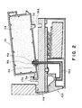
- a recording head 10A in this embodiment is of an ink jet type in which film boiling is produced in the ink in accordance with an electric signal by electrothermal transducer producing thermal energy in response to the electric signal.
- All of the major parts of the constituent elements of the recording head 10A in Figure 1, are laminated, by crimping, on a recording head base plate 11 A with reference indexes of the projections 11A-1 and 11A-2 formed on the recording head base plate 11 A.
- the correct positioning is accomplished between a reference surface 104A-1 of a front plate 101A and a projection 11A-1, and in the vertical direction, the correct positioning is accomplished between the head positioning portion 104A and a projection 11A-2. Further in the direction perpendicular to the sheet of the drawing of Figure 1, the correct positioning is accomplished between the head positioning portion 104A and an unshown projection, of the projection 11A-2, which projects to cover a portion of the head positioning portion 11A.
- a heater board 13A-2 comprises electrothermal transducers (ejection heaters) aligned on a Si base plate and wiring leads of aluminum or the like for supplying electric power thereto. They are produced through film forming technique.
- the heater board 13A-2 is electrically connected by wire bonding with a recording head flexible base plate (head PCB) having electrical leads with pads 13A-1 for receiving electric signals from a main assembly of the apparatus.
- head PCB recording head flexible base plate
- a top plate 12A having grooves is integrally made of polysulfone material or the like so as to be provided with partition walls for defining plural ink passages for the ejection heaters, respectively, a common liquid chamber for supplying through a conduit from an exchangeable ink container 1A to the ink passages, and orifices constituting plural ejection outlets corresponding to the ink passages.
- the top plate 12A is pressed to the heater board 13A-2 by an unshown spring and is fixed and sealed with a sealing material, thus constituting an ink ejection portion.
- the conduit 15A is hermetically connected to the top plate 12A in this embodiment, is penetrated through holes of the head PCB 13A and head base plate 11A to the opposite side of the head base plate 11A and is bonded and fixed at the penetrating portion to the head base plate 11A, thus permitting connection with the exchangeable ink container 1A.
- An end of the conduit 15A which is connectable with the ink container 1A, is provided with a filter 8A to prevent introduction of foreign matter or air to the ejection portion.
- a head cover 18A is provided in order to protect the ejection portion of the recording head 10A and the electrical connection pads 13A-1 and in order to permit easy handling of the recording head 10A.
- the exchangeable ink container 1A is substantially completely filled with ink absorbing material 2A containing the ink, in a container case 1A-1 having inside ribs 1A-2.
- the ink container 1A is provided with an ink supply port 4A for receiving the end of the conduit 15A having the filter 8A, for the ink communication, and an air vent 3A for permitting introduction of the ambient air into the exchangeable ink container 1A by the amount corresponding to the ink consumption from the ink container 1A, thus preventing production of too high vacuum therein.
- the inside surface of the wall of the container case 1A-1 is provided with ribs 1A-2, and in addition, the air vent 3A is disposed at a position away from the ink supply portion 4A.
- the rib 1A-2 also functions to reinforce the container case 1A-1, and in addition, to improve the operativity upon the ink container exchanging manipulation.
- the initial quantity of the ink in the ink absorbing material 24 is slightly smaller than the maximum capacity of the ink absorbing material 2A for the functional purpose of permitting stabilized ejection of the ink by application of negative head (pressure) to the meniscuses at the ejection outlets when the container is connected with the recording head 10A, and also for the operational purpose of preventing ink leakage upon ink container exchanging manipulation even if some impact is applied thereto.
- the ink leakage from the air vent 3A may be limited by water repelling treatment of the ink absorbing material 2A adjacent the air vent 3A or by using additional water repelling absorbing material.
- the ink supply limit of the exchangeable ink container 1A is reached when the quantity of the ink in the ink absorbing material 2A is so small that the ink absorbing force of the ink absorbing material 2A becomes stronger than the ink supply force to the recording head 10A by the capillary force in the ink passage communicating with the ejection outlets, or when the quantity of the air introduced through the air vent 3A to the neighborhood of the filter 8A is so large that a large quantity of the air becomes supplied from the ink absorbing material 2A through the filter 8A.
- connection between the recording head 10A and the exchangeable ink container 1A is accomplished simultaneously with the connection between the recording head 10A and a carriage HC for carrying it, and they are made, in effect, integral by the urging force by a pressure hook 103A of the carriage HC.
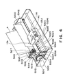
- FIG. 4 shows a recording apparatus usable with a recording head and an exchangeale ink container according to a first embodiment of the present invention.
- a recording material P is fed from the bottom to the top in the drawing, using a platen roller 5000.
- the recording material is pressed to the platen roller 5000 by a sheet confining plate 5002 along a carriage moving direction.
- the carriage HC is engaged and supported by a lead screw 5005 having a helical groove 5004 receiving therein a carriage driving pin and by a slider 5003 extending in parallel with the lead screw 5005.
- the lead screw 5005 functions as a driving source for the carriage, by rotation thereof.
- the carriage HC is reciprocated to the left and right along the record surface of the recording material P confined on the platen roller 5000.
- the lead screw 5005 is rotated and controlled through drive transmission gears 5011, 5010 and 5009 in response to forward and backward rotation of a driving motor 5013.
- a photocoupler constituted by elements 5007 and 5008 function as a home position detecting means to detect a lever 5006 of the carriage HC at the position of the photocoupler, in order to switch the rotational direction of the driving motor 5013.
- the image recording signal is fed to the recording head 10A in timed relation with the movement of the carriage HC carrying thereon the recording head 10A and the exchangeable ink container 1A.
- a supporting member 5016 supports a cap supporting member 5022 for supporting a cap for capping the front side of the recording head.
- a sucking means 5015 functions to suck the inside of the cap to suck the ink from the recording head through an opening 5023 of the cap to recover the ejection of the ink upon necessity.
- a guiding member 5019 permits movement of a cleaning blade 5017 to the front or rear. They are supported on a supporting plate 5018.
- the sucking means or the blade or the like may be of another known form.
- a lever for determining the timing of the sucking and recovery operation moves in accordance with movement of a cam 5020 engaging with the carriage HC, and a driving force from the driving motor 5013 is controlled through a known transmission means including clutch or the like.
- the recovery means is constructed so that when the carriage comes to the home position, the desired processing are carried out at predetermined timed relations at a proper position by operation of the lead screw 5005.
- the mechanical and electrical connections of the recording head 10A and the exchangeable ink container 1A relative to the carriage HC, are accomplished in the following manner.
- the carriage HC is provided with the front plate 101A positioned at a front side of the recording head adjacent to the platen roller, a flexible sheet 102A-1 having recording head driving electrodes 102A corresponding to the pads 13A-1 on the head PCB 13A of the recording head 10A, electric connection supporting plate 100A for urging the flexible sheet 102A-1 from the backside, a recording head positioning portion 104A upon mechanical mounting of the recording head 10A, and a pressure hook 103A for urging the exchangeable ink container 1A and the recording head 10A in one direction.
- a rubber pad may be imposed. In such a case, resilient force is produced to press the flexible sheet from the backside thereof.
- the front plat 101A has two positioning reference surfaces 104A-1, corresponding respectively to the first positioning projection 11A-1 and the second positioning projection 11A-2 on the base plate 11 A of the recording head 10A.
- the pressure hook 103A of the carriage HC produces urging force in a direction inclined approximately 10 degrees from a movement direction of the carriage HC, that is, the pressing direction indicated by a broken line in Figure 1, and therefore, the recording head 10A is urged in the two directions to the front plate 101A and the electric connection supporting plate 100A, by the urging force. Simultaneously, it is urged in the carriage HC movement direction adjacent the head positioning portion 104A with a pivot of the electric connection supporting plate 100A.
- the engaging mechanism of the pressure hook 103A of any known type, but a lever or the like permitting manipulation from the top side of the carriage HC, is preferable.
- the first positioning projection 11A-1 and the second position projection 11 A-2 are contacted to the reference surfaces 104A-1 of the front plate 101A while the recording head 10A and the exchangeable ink container 1A are being slightly rotated on the carriage HC, and thereafter, the electric connection is established. For this reason, the correct positioning between the pads 13A-1 of the head PCB 13A and the head driving electrodes 102A are also assured.
- the recording head 10A and the exchangeable ink container 1A are not completely connected, as shown in Figure 2.
- the carriage HC and the recording head 10A are separated, and the recording head 10A and the exchangeable ink container 1A, are separated.
- the engaging portions are only contacted at this time.
- the engagement between the recording head 10A and the exchangeable ink container 1A starts between the engagement of an engageable hook 17A of the head base plate 10A and an engaging guide 5A of the exchangeable ink container 1A.
- the communication between the inside of the exchangeable ink container 1A and the ambience can be completely prevented. If the prevention or the sealing is incomplete, the ambience is introduced into the inside of the exchangeable ink container 1A in accordance with ink consumption by the recording head 10A not through the ink absorbing material 2A but directly through this portion, and therefore, the ink absorbed in the ink absorbing material 2A is not efficiently used.
- the pressure application direction of the pressure hook 103A is inclined by 10 degrees for the purpose of the correct positioning of the recording head 10A relative to the carriage HC in the direction of the surface of the drawing, and therefore, it is effective to apply the force in the direction perpendicular to the connecting direction also for the connection between the recording head 10A and the exchangeable ink container 1A.
- the force in this direction is provided by the engagement between the container guide 7A and the container guide hole 16A. More particularly, the container guide 7A is contacted to the inside surface of the container guiding hole or groove 16A, and the force produced by the contact is effective to position the carriage HC at the head positioning portion 104A.
- the play of the conduit 15A relative to the ink supplying portion 4A of the exchangeable ink container 1A is selected to be larger than the play of the container guide 7A relative to the guiding groove 16A. Therefore, the force in the direction perpendicular to the engaging direction of the exchangeable ink container is all received by the connecting portion with the container guide 7A. It is a possible alternative structure that the perpendicular force is simultaneously received by the engaging portion between the engaging hook 103A and the engagement guide 5A.
- the connecting portion of the container guide 7A in this embodiment is also given a function of preventing rotation of the exchangeable ink container 1A on the surface of the recording head base plate 11A.
- the plays at the acting surface are so selected that too large force can similarly be avoided.
- the connecting portion of the container guide 7A is disposed adjacent to the engaging portion of the pressure hook 103A (force applying point) in the structure of Figure 1 embodiment so as to avoid too large force applied there, from the standpoint of the mechanical strength of the constituent members. It is further preferable that if the container guide 7A can be disposed outside the pressure or urging means (force application point), it is disposed as far as possible.
- the ring seal 9A is of relatively thick elastic ring in this embodiment so as to permit the play in the ink supply portion 4A and to permit wider connecting portion relative to the outer wall of the exchangeable ink container 1A.
- the recording head 10A and the exchangeable ink container 1A are generally engaged on the carriage HC, and thereafter, the exchangeable ink container 1A is urged in one direction, by which the positioning and connection between the carriage HC and the recording head 10A and the connection between the recording head 10A and the exchangeable ink container 1A, are assuredly accomplished simultaneously.
- ink container and the recording head are independently connectable.
- the electric connection between the carriage HC (the main assembly of the recording apparatus9 and the recording head 10A, are simultaneously established. Therefore, the operativity is good upon the exchange of the recording head 10A and/or the exchangeable ink container 1A.
- the electric connection may be accomplished through a separate connector to permit a higher latitude to further assure the positioning of the recording head and the connection with the exchangeable ink container.
- Figure 3 is a sectional view illustrating the exchangeable ink container 1A before start of use.
- a sealing member including a vent seal 3A-1 and a supply port seal 4A-1 at the air vent 3A and the ink supply portion 4A, respectively.
- the sealing member is removable upon start of use of the exchangeable ink container 1A, by pulling it in the direction of an arrow.
- the embodiment is applicable to a color ink jet recording apparatus having plural recording head capable of ejecting different color inks (four recording heads for ejecting black, cyan, magenta and yellow recording heads, for example).
- the present invention is applicable to a single recording head capable of ejecting plural color inks. In that case, the means for limiting the connecting position and direction for the exchangeable container is added.
- the connecting direction between the carriage HC and the recording head 10A and the connecting direction between the recording head 10A and the exchangeable ink container 1A are substantially the same, and in addition, they are simultaneously connected by urging the exchangeable ink container 1A. Therefore, the operativity in the recording head and/or exchangeable ink container exchanging manipulation, and the mechanical and/or electrical connection therebetween is assured by a simple structure.
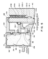
- Figure 5 illustrates the connection between the recording head and/or the exchangeable ink container and the carriage HC.
- the same reference numerals as in the foregoing embodiment are assigned to the elements having the corresponding functions, and the detailed description thereof are omitted for simplicity.
- the recording head 10B scanningly moves above the surface of the recording material while ejecting the ink downwardly. Therefore, the positioning of the recording head 10B in the direction of the surface of the drawing relative to the carriage HC is accomplished, utilizing the weight of the recording head 10B itself, by press-contacting the cut-away portion (not shown) formed in a bottom end of the head base plate 11 B to a reference surface of the electric connection supporting plate of the carriage HC.
- the pressure of the pressure means 103B which is an urging or pressing member on the carriage acts on the recording head 10B through the exchangeable ink container, so that the reference surface of the projection 11 B-1 of the recording head 10B is press-contacted to the reference surface of the carriage at the recording head positioning portion 104B.
- the pads 13B-1 of the head PCB 13B are pressed to the head driving electrodes 102B on the carriage HC by the pressure through the exchangeable ink container 1 B.
- the electric wiring of the recording head 10B is disposed on a flexible head PCB 13B, and in addition, an elastic member 105B is provided on such a side of the recording head 10B of the head base plate 11 B as is opposite from the ejection portion, and therefore, the reliability of the connection is improved as compared with the foregoing embodiment in which the recording head 10B is slightly rotated upon the mounting.
- a reference projection (not shown) for the correct positioning is provided adjacent the rear electrodes of the head base plate 11 B, and in order to further assure the electric connection, an elastic member having larger thickness and higher elasticity than in the foregoing embodiment is disposed as a lower layer of the recording head electrode, so that the proper pressure is assured between the recording head PCB and the head driving electrode upon the pressure contact of the reference projection.
- the pressure applied to the recording head through the exchangeable ink container is received by the reference projections disposed at the front and rear of the head base plate.
- the conduit 15B in this embodiment is disposed right above the liquid chamber 14B, and is so constructed that it is connected with the exchangeable ink container 1B at the ejecting portion side of the head base plate 11 B. Since it does not penetrate through the head base plat 11 B, the conduit 15B can be easily made shorter and larger, so that flow resistance of the conduit 15B can be reduced as compared with the first embodiment. Therefore, the pressure loss or drop upon the ink supply to the recording head 10B can be increased. This is advantageous when the recording frequency is increased.
- the pressure or force for the connection between the exchangeable ink container 1 B and the recording head 10B is more easily applied to the ejection portion through the conduit 15B, and therefore, in this embodiment the mechanical strength of the liquid passage forming member 15B-1 and, in addition, the conduit 15B is directly fixed and supported on the head base plate 11 B.
- the hermetical sealing of the connecting portion between the conduit 15B and the liquid chamber 14B is accomplished by application of sufficient sealing material.
- the structure of the recording head 10B of this embodiment is such that the heater board 13B and the top plate 12B are laminated on the head base plate 11 B, and therefore, the pressure or force acting through the exchangeable ink container 1 B may be adjusted to a proper level, and thereafter, the connecting force is reinforced.
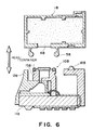
- the description will be made as to the mounting and dismounting of the recording head 10B and the exchangeable ink container 1 B.
- the recording head 10B and the exchangeable ink container 1B of this embodiment may be mounted or dismounted after they are taking out of the recording apparatus. It is a possible alternative for making easier the mounting or dismounting thereof relative to the carriage HC that an auxiliary means to permit mounting or dismounting manipulation on the carriage HC.
- the mounting or dismounting of the recording head 10B and the exchangeable ink container 1B relative to each other is carried out using a container guide 16B and an engaging guide 5B of the ink supply portion 4B.
- the container guide 16B functions to roughly limit rotation of the exchangeable ink container 1 B on the top surface of the recording head 10B, and there is provided a play to avoid objection to the engagement of the engaging guide 5B for the ink supply portion 4B.
- the engagement is established between the engaging guide 5B elastically deformable and provided in the exchangeable ink container 1B and a recess of the liquid passage forming member 15B-1 supported on the head base plate 11 B of the recording head 10B.
- the free end of the engaging guide 5B is rounded.
- the number of the engaging guides may be further increased, or it may be cylindrical.
- the engaging portion of the passage forming member may be other than non-cylindrical.
- the elastic force of the engaging guide 5B is not strong, and therefore, in the state of Figure 6, the connection engagement of the ink supply portion 4B is not sufficient.
- the deformation and contact of the ring seal 9B and the contact between the filter 8B and the ink absorbing material 2B are also insufficient.
- the connecting or jointing force is of such a degree as to permit integral exchange of the recording head 10B and the exchangeable ink container 1 B.
- the recording head 10B and the exchangeable ink container 1B thus connected lightly is mounted on the carriage HC of the main assembly of the recording apparatus, as shown in Figure 5.
- a reference surface of the positioning projection 11 B-1 of the recording head 10B is engaged to the head positioning portion 104B of the carriage HC, and thereafter, the exchangeable ink container 1 B is pressed by the pressure application means 103B on the carriage HC in the direction indicated by a broken line in Figure 5.
- the recording head 10B is crimped on the carriage HC, and the recording head 10B and the exchangeable ink container 1 B are completely connected.
- the engaging guide 5B of the exchangeable ink container 1B is inserted further deeply beyond the limitation of the recess of the passage forming member 15B-1, so that the filter 8B of the end of the conduit 15B and the ink absorbing material 2B of the ink supply portion 4B are sufficiently closely contacted to permit ink supply.
- the ring seal 9B elastically deforms to provide hermetical sealing to prevent direct communication with the ambience at the connecting portion. Even in this state, the container guide 16B permits sufficient clearance in the connecting direction between the recording head 10B and the exchangeable ink container 1B so as to avoid too large force in the connection at the ink supply portion 4B.
- the exchangeable ink container 1 C may be in the form of a cylinder, as shown in Figure 8, to permit free connecting direction of the exchangeable ink container 1 C on the top surface of the recording head (rotatable structure), thus eliminating the necessity of the container guide.
- the connecting or engagement direction between the carriage HC and the recording head 10B and that between the recording head 10B and the exchangeable ink container 1 B are made completely the same, and in addition, they are connected simultaneously by urging the exchangeable ink container 1B. Therefore, the operativity is good upon exchange of the recording head and/or the exchangeable ink container. Furthermore, the mechanical or electrical connection is further assured with simple structure. Additionally, since the recording head 10B and the exchangeable ink container 1B can be unified even when they are not mounted on the carriage, the operativity in the exchanging manipulation can be further improved.
- the recording head 1 of this embodiment is of an ink jet type in which film boiling is produced in the ink in response to electric signal by thermal energy provided by electrothermal transducer responsive to the electric signal.
- All of the major parts of the constituent elements of the recording head 101 C in Figure 9, are laminated, by crimping, on a recording head base plate 11C with reference indexes of the projections 11C-1 and 11C-2 formed on the recording head base plate 11 C.
- the correct positioning is accomplished between a reference surface 104C-1 of a front plate 101 C and a projection 11C-1, and in the vertical direction, the correct positioning is accomplished between the head front plate 101C and a projection 11C-2. Further in the direction perpendicular to the sheet of the drawing of Figure 9, the correct positioning is accomplished between the front plate 101 C and an unshown projection, of the projection 11C-2, which projects to cover a portion of the front plate 101 C.
- a heater board 13C-2 comprises electrothermal transducers (ejection heaters) aligned on a Si base plate and wiring leads of aluminum or the like for supplying electric power thereto. They are produced through film forming technique.
- the heater board 13C-2 is electrically connected by wire bonding with a recording head flexible base plate (head PCB 13C) having electrical leads with pads for receiving electric signals from a main assembly of the apparatus.
- a top plate 12C having grooves is integrally made of polysulfone material or the like so as to be provided with partition walls for defining plural ink passages for the ejection heaters, respectively, a common liquid chamber for supplying through a conduit from an ink container 1 C to the ink passages, and orifices constituting plural ejection outlets corresponding to the ink passages.
- the top plate 12C is pressed to the heater board 13C by an unshown spring and is fixed and sealed with a sealing material, thus constituting an ink ejection portion.
- the conduit 15C is hermetically connected to the top plate 12C in this embodiment, is penetrated through holes of the head PCB 13C and head base plate 11 C to the opposite side of the head base plate 11 C and is bonded and fixed at the penetrating portion to the head base plate 11 C, thus permitting connection with the ink container 1C.
- An end of the conduit 15C which is connectable with the ink container 1 C, is provided with a filter 8C to prevent introduction of foreign matter or air to the ejection portion.
- a head cover 18C is provided in order to protect the ejection portion of the recording head 10C and the electrical connection pads and in order to permit easy handling of the recording head 10C.
- the ink container 1 C is substantially completely filled with ink absorbing material 2C containing the ink, in a container case having inside ribs 1 C-2.
- the ink container 1C is provided with an ink supply port 4C for receiving the end of the conduit 15C having the filter 8C, for the ink communication, and an air vent 3C for permitting introduction of the ambient air into the ink container 1C by the amount corresponding to the ink consumption from the ink container 1C, thus preventing production of too high vacuum therein.
- the inside surface of the wall of the container case 1 C-1 is provided with ribs 1 C-2, and in addition, the air vent 3C is disposed at a position away from the ink supply portion 4C.
- the rib 1 C-2 also functions to reinforce the container case, and in addition, to improve the operativity upon the ink container exchanging manipulation.
- the initial quantity of the ink in the ink absorbing material 2C is slightly smaller than the maximum capacity of the ink absorbing material 2C for the functional purpose of permitting stabilized ejection of the ink by application of negative head (pressure) to the meniscuses at the ejection outlets when the container is connected with the recording head 10C, and also for the operational purpose of preventing ink leakage upon ink container exchanging manipulation even if some impact is applied thereto.
- the ink leakage from the air vent 3C may be limited by water repelling treatment of the ink absorbing material 2C adjacent the air vent 3C or by using additional water repelling absorbing material.
- the ink supply limit of the ink container 1 C is reached when the quantity of the ink in the ink absorbing material 2C is so small that the ink absorbing force of the ink absorbing material 2C becomes stronger than the ink supply force to the recording head 10C by the capillary force in the ink passage communicating with the ejection outlets, or when the quantity of the air introduced through the air vent 3C to the neighborhood of the filter 8C is so large that a large quantity of the air becomes supplied from the ink absorbing material 2C through the filter 8C.
- connection between the recording head 10C and the ink container 1 C are accomplished in the following manner.
- a container belt 22 having an end (not shown) fixed to the head base plate 11 C of the recording head 10C is disposed along the outer surface of the ink container 1 C adjacent the ink passage connecting portion, and a container belt hook 24 in the form of a ring at an end of a container belt spring 23 connected to the other end of the container belt, is pulled and hooked on a projection 25 of the head base plate 11 C, by which they are unified by the urging force of the container belt spring 23.
- the connection between the ink container 1 C and the recording head 10C can be carried out outside the carriage HC.
- the container guide of the ink container 1 C is engaged into a container guide hole 16C of the head base plate 11 C.
- the position of this engagement is disposed close to an acting point of the pressure hook 103C of the carriage HC and the ink passage connecting portion (ink supply portion) is disposed as far as possible from an acting point of the pressure hook 103C, by which the component force of the pressure at the ink supply portion upon the mounting of the carriage HC can be reduced, thus permitting the assured engagement at the ink passage connecting portion.
- the pressure or force of the pressure hook 103C (force applying point) to the ink container 1 C rotates the ink container 1C in the clockwise direction in the Figure.
- the ink passage connecting portion is a force acting point with the fulcrum of the engaging portion of the container guide 7C, and therefore, the force against the engagement is produced in the ink passage connecting portion.
- the ink absorbing material 2C and the filter 8C are press-contacted with each other to establish the connection at the ink passage connecting portion, and in addition, the elastic ring seal 9C interposed between the head base plate 11 C and the ink container 1 C outer surface, is pressed and deformed to be in close contact with both of them, so that the connection between the ambience and the inside of the ink container 1C is completely prevented at the ink passage connecting portion.
- the connecting force adjacent the ink passage connecting portion provided by the container belt spring 23 is made sufficiently larger than the acting force of the pressure hook 103C, and therefore, the assured ink communication is established upon the mounting to the carriage HC.
- the pressure hook 103C provides the pressing direction which is inclined by 10 degrees so as to position the recording head 10C relative to the carriage HC to the left on the Figure. If the pressure hook 103C is hooked on the head base plate 11 C, the configuration of the head base plate will be complicated. Therefore, in this embodiment, it is hooked on the ink container 1C in which the tolerance in the positional accuracy is relatively large.
- the force in a direction perpendicular to the connecting direction is produced.
- such a force is received by the engagement between the container guide 7C and a hole of a container guide 16C. Therefore, the container guide 7C is contacted to the inside surface at the left in the drawing of the container guide groove 16C, and the recording head 10C received the force at the head positioning portion, so that it is correctly positioned relative to and connected with the carriage HC.
- the play of the conduit in the ink supply portion 4C of the ink container 1 C is selected to be larger than the play of the container guide 7C in the container guide groove 16C, so that all of the force in a direction perpendicular to the connecting direction of the ink container 1 C is received by the connecting portion.
- the connecting portion of the container guide 7C in this embodiment is given a further function of preventing rotation of the ink container 1 C on the head base plate 11 C, and the play thereof on the acting surface is selected to avoid too large force to the liquid passage, similarly.
- the ring seal 9C in order to permit the play of the ink supply portion 4C, is so selected to provide a wide connecting portion relative to the ink container 1C outer surface, by taking a form of slightly thick elastic ring.
- the carriage HC is provided with a front plate 101 C at a front side of the recording head (platen roller side), electric connection supporting plate 102C-1 for supporting recording head driving electrodes corresponding to the pads on the PCB 13C of the recording head 10C, a head positioning portion 104C upon mechanical mounting of the recording head 10C, and a pressure application hook 103C for urging the ink container 1 C and the recording head 10C in one direction.
- the pressure hook 103C of the carriage HC is such as to produce the urging force in a direction approximately 10 degrees away from the moving direction of the carriage HC, that is, the direction shown in Figure 9. Therefore, the recording head 10C is urged by the urging force in two directions to the front plate 101 C and to the electric connection supporting plate 102C-1.
- the pressure applying engaging mechanism of the hook 103C may be of any known form, but a lever or the like manipulatable at the top of the carriage HC is desirable.
- the electric connection is established after the positioning projections 11 C-1 and 11C-2 are contacted to the reference surface of the front plate 101 C while the recording head 10C and the ink container 1 C are being slightly rotated on the carriage HC, and therefore, the positioning between the pads of the head PCB 13C and the head driving electrodes 102C, are assured, too.
- the ink container 1 C and the recording head 10C are sufficiently engaged, and thereafter, the ink container 1 C is urged by the pressure hook 103C, by which the positioning of the carriage HC and the recording head 10C is assuredly carried out with a simple structure.
- the recording head 10C and the ink container 1 C may be removed from the carriage HC, and they can be connected or separated relative to each other outside the main assembly of the recording apparatus, and therefore, the exchanging manipulation is made easier.
- the electric connection is established simultaneously between the carriage (main assembly of the recording apparatus) HC and the recording head 10C, and the operativity in the exchange of the recording head 10C and the ink container 1 C is good.
- the electric connection may be established using a separate connector or the like so as to provide a higher latitude to further assure the positioning of the recording head 10C and the connection with the ink container 1 C.
- the present invention is applicable to a color ink jet recording apparatus having plural recording heads capable of ejecting different color inks (black, cyan, magenta and yellow recording heads (four heads), for example).
- the present invention is applicable to a single recording head capable of ejecting plural color inks.
- the limiting means for limiting the connecting position and direction for the ink container is added.
- the ink is retained by the ink absorbing material as an example, but the ink container may be in the form of a bladder type.
- the present invention is particularly suitably usable in an ink jet recording head and recording apparatus wherein thermal energy by an electrothermal transducer, laser beam or the like is used to cause a change of state of the ink to eject or discharge the ink. This is because the high density of the picture elements and the high resolution of the recording are possible.
- the typical structure and the operational principle are preferably the ones disclosed in U.S. Patent Nos. 4,723,129 and 4,740,796.
- the principle and structure are applicable to a so-called on-demand type recording system and a continuous type recording system.
- it is suitable for the on-demand type because the principle is such that at least one driving signal is applied to an electrothermal transducer disposed on a liquid (ink) retaining sheet or liquid passage, the driving signal being enough to provide such a quick temperature rise beyond a departure from nucleation boiling point, by which the thermal energy is provided by the electrothermal transducer to produce film boiling on the heating portion of the recording head, whereby a bubble can be formed in the liquid (ink) corresponding to each of the driving signals.
- the liquid (ink) is ejected through an ejection outlet to produce at least one droplet.
- the driving signal is preferably in the form of a pulse, because the development and contraction of the bubble can be effected instantaneously, and therefore, the liquid (ink) is ejected with quick response.
- the driving signal in the form of the pulse is preferably such as disclosed in U.S. Patents Nos. 4,463,359 and 4,345,262.
- the temperature increasing rate of the heating surface is preferably such as disclosed in U.S. Patent No. 4,313,124.
- the structure of the recording head may be as shown in U.S. Patent Nos. 4,558,333 and 4,459,600 wherein the heating portion is disposed at a bent portion, as well as the structure of the combination of the ejection outlet, liquid passage and the electrothermal transducer as disclosed in the above- mentioned patents.
- the present invention is applicable to the structure disclosed in Japanese Laid-Open Patent Application No. 123670/1984 wherein a common slit is used as the ejection outlet for plural electrothermal transducers, and to the structure disclosed in Japanese Laid-Open Patent Application No. 138461/1984 wherein an opening for absorbing pressure wave of the thermal energy is formed corresponding to the ejecting portion. This is because the present invention is effective to perform the recording operation with certainty and at high efficiency irrespective of the type of the recording head.
- the present invention is effectively applicable to a so-called full-line type recording head having a length corresponding to the maximum recording width.
- a recording head may comprise a single recording head and plural recording head combined to cover the maximum width.
- the present invention is applicable to a serial type recording head wherein the recording head is fixed on the main assembly, to a replaceable chip type recording head which is connected electrically with the main apparatus and can be supplied with the ink when it is mounted in the main assembly, or to a cartridge type recording head having an integral ink container.
- the provisions of the recovery means and/or the auxiliary means for the preliminary operation are preferable, because they can further stabilize the effects of the present invention.
- preliminary heating means which may be the electrothermal transducer, an additional heating element or a combination thereof.
- means for effecting preliminary ejection (not for the recording operation) can stabilize the recording operation.
- the recording head mountable may be a single corresponding to a single color ink, or may be plural corresponding to the plurality of ink materials having different recording color or density.
- the present invention is effectively applicable to an apparatus having at least one of a monochromatic mode mainly with black, a multi-color mode with different color ink materials and/or a full-color mode using the mixture of the colors, which may be an integrally formed recording unit or a combination of plural recording heads.
- the ink has been liquid. It may be, however, an ink material which is solidified below the room temperature but liquefied at the room temperature. Since the ink is controlled within the temperature not lower than 30 °C and not higher than 70 °C to stabilize the viscosity of the ink to provide the stabilized ejection in usual recording apparatus of this type, the ink may be such that it is liquid within the temperature range when the recording signal is the present invention is applicable to other types of ink. In one of them, the temperature rise due to the thermal energy is positively prevented by consuming it for the state change of the ink from the solid state to the liquid state. Another ink material is solidified when it is left, to prevent the evaporation of the ink.
- the ink is liquefied, and the liquefied ink may be ejected.
- Another ink material may start to be solidified at the time when it reaches the recording material.
- the present invention is also applicable to such an ink material as is liquefied by the application of the thermal energy.
- Such an ink material may be retained as a liquid or solid material in through holes or recesses formed in a porous sheet as disclosed in Japanese Laid-Open Patent Application No. 56847/1979 and Japanese Laid-Open Patent Application No. 71260/1985. The sheet is faced to the electrothermal transducers. The most effective one for the ink materials described above is the film boiling system.
- the ink jet recording apparatus may be used as an output terminal of an information processing apparatus such as computer or the like, as a copying apparatus combined with an image reader or the like, or as a facsimile machine having information sending and receiving functions.
- An ink jet recording apparatus for ejecting ink to effect recording on a recording material includes a carriage movable in a direction different from a direction in which the recording material is fed; pressing mechanism for pressing an end of an ink container for containing ink to be supplied to an ink jet recording head, wherein the pressing mechanism is effective to mount on the carriage the ink container and the ink jet recording head which are connected with each other by a connecting mechanism.
Landscapes
- Ink Jet (AREA)
Applications Claiming Priority (4)
| Application Number | Priority Date | Filing Date | Title |
|---|---|---|---|
| JP35104591A JP3103177B2 (ja) | 1991-12-11 | 1991-12-11 | インクタンク・ヘッド交換型インクジェット記録装置 |
| JP327560/91 | 1991-12-11 | ||
| JP32756091A JP3165204B2 (ja) | 1991-12-11 | 1991-12-11 | インクタンク,記録ヘッド分離交換型インクジェット記録装置 |
| JP351045/91 | 1991-12-11 |
Publications (3)
| Publication Number | Publication Date |
|---|---|
| EP0546544A2 true EP0546544A2 (de) | 1993-06-16 |
| EP0546544A3 EP0546544A3 (de) | 1994-03-16 |
| EP0546544B1 EP0546544B1 (de) | 1999-03-31 |
Family
ID=26572544
Family Applications (1)
| Application Number | Title | Priority Date | Filing Date |
|---|---|---|---|
| EP92121069A Expired - Lifetime EP0546544B1 (de) | 1991-12-11 | 1992-12-10 | Tintenstrahlaufzeichnungsgerät |
Country Status (5)
| Country | Link |
|---|---|
| US (1) | US5448274A (de) |
| EP (1) | EP0546544B1 (de) |
| KR (1) | KR970007626B1 (de) |
| CA (1) | CA2084708C (de) |
| DE (1) | DE69228791T2 (de) |
Cited By (16)
| Publication number | Priority date | Publication date | Assignee | Title |
|---|---|---|---|---|
| EP0611656A3 (en) * | 1993-01-01 | 1994-09-21 | Canon Kk | Ink refilling container and ink refilling method using same. |
| EP0581298A3 (en) * | 1992-07-31 | 1994-09-21 | Canon Kk | Ink jet recording head, ink jet recording head cartridge, recording apparatus using the same and method of manufacturing the head |
| EP0646465A3 (de) * | 1993-09-30 | 1995-08-23 | Canon Kk | Tinte für Tintenstrahlkassette und Verfahren zur Tintenstrahl-Aufzeichnung mit dieser Tinte. |
| DE19512812A1 (de) * | 1994-11-29 | 1996-05-30 | Hewlett Packard Co | Nachfüllverfahren und Nachfüllvorrichtung für Tintenkassetteneinheiten |
| EP0710568A3 (de) * | 1994-11-02 | 1996-07-24 | Seiko Epson Corp | Tintenstrahlaufzeichner und zugehöriger Drucker |
| US5583549A (en) * | 1992-07-31 | 1996-12-10 | Canon Kabushiki Kaisha | Liquid storing container for recording apparatus |
| EP0730975A3 (de) * | 1995-03-06 | 1997-11-26 | Hewlett-Packard Company | Nachgiebige Verbindungsanordnung zur Montage einer abnehmbaren Tintenpatrone auf einem Druckwagen |
| EP0756937A3 (de) * | 1995-08-01 | 1998-06-10 | Brother Kogyo Kabushiki Kaisha | Verbindungsstruktur für Druckkopfbefestigung und Farbstoffpatronen |
| EP0739741A3 (de) * | 1995-04-24 | 1999-02-03 | Canon Kabushiki Kaisha | Tintenbehälter und Verfahren zu dessen Herstellung |
| US6170939B1 (en) | 1992-07-31 | 2001-01-09 | Canon Kabushiki Kaisha | Liquid storing container for recording apparatus |
| US6179416B1 (en) | 1993-08-23 | 2001-01-30 | Canon Kabushiki Kaisha | Exchangeable ink cartridge |
| US6328422B1 (en) | 1991-12-19 | 2001-12-11 | Canon Kabushiki Kaisha | Ink jet head cartridge having a folded wiring member |
| SG85678A1 (en) * | 1993-11-29 | 2002-01-15 | Canon Kk | Improved ink container, installing-removing method therefore, and apparatus usable with the same |
| US7290843B2 (en) | 1995-07-14 | 2007-11-06 | Canon Kabushiki Kaisha | Recording apparatus having a device for detecting the presence or absence of a liquid |
| EP1905594A1 (de) | 2006-09-27 | 2008-04-02 | Ninestar Image Co., Ltd. | Tintenkassettehalterung für Druckgeräthaltevorrichtung |
| CN103158364A (zh) * | 2011-12-13 | 2013-06-19 | 株式会社理光 | 图像形成装置 |
Families Citing this family (37)
| Publication number | Priority date | Publication date | Assignee | Title |
|---|---|---|---|---|
| EP0860285B1 (de) * | 1991-12-11 | 2002-03-06 | Canon Kabushiki Kaisha | Tintenstrahlpatrone |
| US6003985A (en) * | 1991-12-11 | 1999-12-21 | Canon Kabushiki Kaisha | Ink jet recording apparatus |
| US6286944B1 (en) * | 1993-05-21 | 2001-09-11 | Canon Kabushiki Kaisha | Ink jet unit with cartridge having controlled ink flow |
| JP3188056B2 (ja) * | 1993-07-21 | 2001-07-16 | キヤノン株式会社 | インクジェット記録装置およびインクジェットヘッド |
| US5565900A (en) * | 1994-02-04 | 1996-10-15 | Hewlett-Packard Company | Unit print head assembly for ink-jet printing |
| EP0879703B2 (de) * | 1994-08-24 | 2009-05-13 | Canon Kabushiki Kaisha | Tintenbehälter für Tintenstrahldrucker, Halter für den Behälter, Druckwagen für den Halter und Tintenstrahldrucker |
| JPH08207304A (ja) * | 1994-11-03 | 1996-08-13 | Xerox Corp | インク供給カートリッジ及びインクジェットプリンタ |
| JP3391924B2 (ja) * | 1995-01-31 | 2003-03-31 | キヤノン株式会社 | 画像記録装置 |
| US6022103A (en) * | 1995-02-07 | 2000-02-08 | Canon Kabushiki Kaisha | Method for positioning an ink cartridge, and the ink cartridge and ink jet recording apparatus used for such method |
| JP3576694B2 (ja) | 1996-04-23 | 2004-10-13 | キヤノン株式会社 | インクジェット記録方法、その装置、画像処理方法及び画像処理方法を実行するプリント方法 |
| DE69725043T2 (de) | 1996-04-23 | 2004-07-08 | Canon K.K. | Tintenstrahldrucksystem, Verfahren und Apparat zum Tintenstrahldrucken |
| JPH1067127A (ja) * | 1996-04-23 | 1998-03-10 | Canon Inc | インクジェット記録装置及び画像処理方法 |
| JPH09286125A (ja) | 1996-04-23 | 1997-11-04 | Canon Inc | インクジェット記録方法及びその装置 |
| JP3413052B2 (ja) * | 1996-04-23 | 2003-06-03 | キヤノン株式会社 | インクジェット記録装置及び制御方法 |
| KR100186618B1 (ko) * | 1996-09-16 | 1999-05-15 | 삼성전자주식회사 | 피그먼트 잉크의 농도 균일화방법 |
| KR100195908B1 (ko) * | 1996-10-28 | 1999-06-15 | 윤종용 | 잉크젯 프린터의 헤드 구조 |
| JP2001010078A (ja) | 1999-04-27 | 2001-01-16 | Canon Inc | インクタンク、該インクタンクが取り付けられるホルダー、該ホルダーを備えたインクジェット記録装置、インクタンクのホルダーへの装着方法 |
| DE60031213T2 (de) * | 1999-09-03 | 2007-08-23 | Canon K.K. | Flüssigkeitsdruckkopf, Drucker, und Verfahren zum positionieren des Flüssigkeitsdruckkopfs im Drucker |
| JP2002254673A (ja) * | 2000-12-25 | 2002-09-11 | Seiko Epson Corp | インクジェット記録装置用インクカートリッジ |
| JP4095308B2 (ja) | 2001-02-09 | 2008-06-04 | キヤノン株式会社 | カートリッジ、キャリッジ、インクジェット記録装置および記録ヘッド |
| US6666542B2 (en) * | 2001-03-30 | 2003-12-23 | Brother Kogyo Kabushiki Kaisha | Ink cartridge for printer or the like and ink cartridge positioning and locking mechanism |
| JP3774675B2 (ja) | 2001-05-10 | 2006-05-17 | キヤノン株式会社 | パッケージ |
| JP4027111B2 (ja) * | 2002-02-15 | 2007-12-26 | キヤノン株式会社 | 液体噴射記録ヘッド |
| US6776479B2 (en) * | 2002-10-31 | 2004-08-17 | Hewlett-Packard Development Company, L.P. | Fluid interconnect port venting for capillary reservoir fluid containers, and methods |
| JP4862683B2 (ja) * | 2007-02-19 | 2012-01-25 | ブラザー工業株式会社 | インクカートリッジ |
| JP5483909B2 (ja) * | 2009-03-10 | 2014-05-07 | キヤノン株式会社 | インクジェット記録装置 |
| US8646884B2 (en) * | 2010-01-26 | 2014-02-11 | Brother Kogyo Kabushiki Kaisha | Liquid supply apparatus and image recording apparatus |
| RU2594874C2 (ru) | 2012-01-12 | 2016-08-20 | Сейко Эпсон Корпорейшн | Картридж и система подачи печатающего материала |
| US9278552B2 (en) | 2012-06-06 | 2016-03-08 | Canon Kabushiki Kaisha | Ink jet printing apparatus and control method thereof |
| JP6098449B2 (ja) * | 2013-09-09 | 2017-03-22 | ブラザー工業株式会社 | 保護キャップ |
| JP6203025B2 (ja) | 2013-12-10 | 2017-09-27 | キヤノン株式会社 | 記録装置および記録データの処理方法 |
| JP6498098B2 (ja) * | 2015-10-30 | 2019-04-10 | キヤノン株式会社 | 記録装置および液体収容部材 |
| WO2017115580A1 (ja) | 2015-12-28 | 2017-07-06 | セイコーエプソン株式会社 | 液体供給ユニット |
| JPWO2017115582A1 (ja) * | 2015-12-28 | 2018-10-18 | セイコーエプソン株式会社 | 液体供給ユニット |
| EE01402U1 (et) * | 2016-05-18 | 2017-07-17 | Natufia Labs Oü | Süsteem täitekasseti lukustamiseks ja tühjendamiseks täitekasseti vastuvõtupesas |
| JP7287033B2 (ja) | 2019-03-20 | 2023-06-06 | セイコーエプソン株式会社 | 液体吐出ユニットおよび液体吐出装置 |
| JP7459493B2 (ja) * | 2019-12-05 | 2024-04-02 | セイコーエプソン株式会社 | 液体吐出装置 |
Family Cites Families (25)
| Publication number | Priority date | Publication date | Assignee | Title |
|---|---|---|---|---|
| DE260894C (de) * | 1900-01-01 | |||
| CA1127227A (en) * | 1977-10-03 | 1982-07-06 | Ichiro Endo | Liquid jet recording process and apparatus therefor |
| JPS5936879B2 (ja) * | 1977-10-14 | 1984-09-06 | キヤノン株式会社 | 熱転写記録用媒体 |
| US4330787A (en) * | 1978-10-31 | 1982-05-18 | Canon Kabushiki Kaisha | Liquid jet recording device |
| US4345262A (en) * | 1979-02-19 | 1982-08-17 | Canon Kabushiki Kaisha | Ink jet recording method |
| US4463359A (en) * | 1979-04-02 | 1984-07-31 | Canon Kabushiki Kaisha | Droplet generating method and apparatus thereof |
| US4313124A (en) * | 1979-05-18 | 1982-01-26 | Canon Kabushiki Kaisha | Liquid jet recording process and liquid jet recording head |
| JPS5656874A (en) * | 1979-10-17 | 1981-05-19 | Canon Inc | Ink jet recording device |
| US4558333A (en) * | 1981-07-09 | 1985-12-10 | Canon Kabushiki Kaisha | Liquid jet recording head |
| JPS59123670A (ja) * | 1982-12-28 | 1984-07-17 | Canon Inc | インクジエツトヘツド |
| JPS59138461A (ja) * | 1983-01-28 | 1984-08-08 | Canon Inc | 液体噴射記録装置 |
| JPS6071260A (ja) * | 1983-09-28 | 1985-04-23 | Erumu:Kk | 記録装置 |
| JPS60204343A (ja) * | 1984-03-30 | 1985-10-15 | Canon Inc | インクジエツト記録装置 |
| JPS60204342A (ja) * | 1984-03-30 | 1985-10-15 | Canon Inc | インクジエツト記録装置 |
| JPS60204323A (ja) * | 1984-03-30 | 1985-10-15 | Canon Inc | 液体噴射記録装置の記録ヘツド |
| US4633274A (en) * | 1984-03-30 | 1986-12-30 | Canon Kabushiki Kaisha | Liquid ejection recording apparatus |
| US4635080A (en) * | 1984-03-30 | 1987-01-06 | Canon Kabushiki Kaisha | Liquid injection recording apparatus |
| JP2510083B2 (ja) * | 1984-07-09 | 1996-06-26 | キヤノン株式会社 | インクジエツト記録装置 |
| JPS633958A (ja) * | 1986-06-24 | 1988-01-08 | Canon Inc | インク供給装置 |
| US4872026A (en) * | 1987-03-11 | 1989-10-03 | Hewlett-Packard Company | Ink-jet printer with printhead carriage alignment mechanism |
| JP2983990B2 (ja) * | 1988-07-29 | 1999-11-29 | キヤノン株式会社 | インクジェット記録装置 |
| EP0602020B1 (de) * | 1988-12-29 | 1998-06-10 | Canon Kabushiki Kaisha | Tintenstrahlaufzeichnungskopf und Tintenstrahlaufzeichnungsgerät |
| DE69019834T2 (de) * | 1989-01-17 | 1995-12-07 | Canon Kk | Tintenstrahldruckvorrichtung und Verfahren zum Einbau eines Tintenstrahldruckkopfes in eine Tintenstrahldruckvorrichtung. |
| AU626457B2 (en) * | 1989-09-18 | 1992-07-30 | Canon Kabushiki Kaisha | Ink jet recording head and ink jet recording apparatus having same |
| US4990938A (en) * | 1989-12-04 | 1991-02-05 | Eastman Kodak Company | Printer nest for positioning ink jet print/cartridge |
-
1992
- 1992-12-07 CA CA002084708A patent/CA2084708C/en not_active Expired - Fee Related
- 1992-12-10 KR KR1019920023822A patent/KR970007626B1/ko not_active Expired - Fee Related
- 1992-12-10 DE DE69228791T patent/DE69228791T2/de not_active Expired - Lifetime
- 1992-12-10 EP EP92121069A patent/EP0546544B1/de not_active Expired - Lifetime
-
1995
- 1995-01-15 US US08/372,831 patent/US5448274A/en not_active Expired - Lifetime
Cited By (36)
| Publication number | Priority date | Publication date | Assignee | Title |
|---|---|---|---|---|
| US6328422B1 (en) | 1991-12-19 | 2001-12-11 | Canon Kabushiki Kaisha | Ink jet head cartridge having a folded wiring member |
| GB2302843B (en) * | 1992-07-31 | 1997-03-26 | Canon Kk | Liquid storing container for recording apparatus |
| GB2269784B (en) * | 1992-07-31 | 1997-03-19 | Canon Kk | Liquid storing container for recording apparatus |
| US6170939B1 (en) | 1992-07-31 | 2001-01-09 | Canon Kabushiki Kaisha | Liquid storing container for recording apparatus |
| EP0581298A3 (en) * | 1992-07-31 | 1994-09-21 | Canon Kk | Ink jet recording head, ink jet recording head cartridge, recording apparatus using the same and method of manufacturing the head |
| US5583549A (en) * | 1992-07-31 | 1996-12-10 | Canon Kabushiki Kaisha | Liquid storing container for recording apparatus |
| US5589862A (en) * | 1992-07-31 | 1996-12-31 | Canon Kabushiki Kaisha | Liquid storing container for recording apparatus |
| GB2302843A (en) * | 1992-07-31 | 1997-02-05 | Canon Kk | Mechanism for connecting an ink jet recording head to an ink tank cartridge |
| US5652608A (en) * | 1992-07-31 | 1997-07-29 | Canon Kabushiki Kaisha | Ink jet recording head, ink jet recording head cartridge, recording apparatus using the same and method of manufacturing the head |
| US6164765A (en) * | 1993-01-01 | 2000-12-26 | Canon Kabushiki Kaisha | Ink refilling container and ink refilling method using same |
| EP0611656A3 (en) * | 1993-01-01 | 1994-09-21 | Canon Kk | Ink refilling container and ink refilling method using same. |
| US6179416B1 (en) | 1993-08-23 | 2001-01-30 | Canon Kabushiki Kaisha | Exchangeable ink cartridge |
| EP0646465A3 (de) * | 1993-09-30 | 1995-08-23 | Canon Kk | Tinte für Tintenstrahlkassette und Verfahren zur Tintenstrahl-Aufzeichnung mit dieser Tinte. |
| US6164772A (en) * | 1993-09-30 | 2000-12-26 | Canon Kabushiki Kaisha | Ink for ink jet cartridge and method of ink jet recording using the same |
| US5796417A (en) * | 1993-10-29 | 1998-08-18 | Hewlett-Packard Company | Compliant interconnect assembly for mounting removable print cartridges in a carriage |
| SG85678A1 (en) * | 1993-11-29 | 2002-01-15 | Canon Kk | Improved ink container, installing-removing method therefore, and apparatus usable with the same |
| EP0710568A3 (de) * | 1994-11-02 | 1996-07-24 | Seiko Epson Corp | Tintenstrahlaufzeichner und zugehöriger Drucker |
| US6170940B1 (en) | 1994-11-02 | 2001-01-09 | Seiko Epson Corporation | Ink jet type recording unit, and printer with it |
| EP0927641A1 (de) * | 1994-11-02 | 1999-07-07 | Seiko Epson Corporation | Tintenstrahl-Aufzeichnungseinheit |
| EP0847866A3 (de) * | 1994-11-02 | 1998-07-08 | Seiko Epson Corporation | Tintenzufuhrbehälter für eine Tintenstrahlaufzeichnungseinheit |
| DE19512812C2 (de) * | 1994-11-29 | 2003-11-27 | Hewlett Packard Co | Nachfülleinheit für eine Einfügung in eine leere Tintenkassetteneinheit |
| DE19512812A1 (de) * | 1994-11-29 | 1996-05-30 | Hewlett Packard Co | Nachfüllverfahren und Nachfüllvorrichtung für Tintenkassetteneinheiten |
| EP0730975A3 (de) * | 1995-03-06 | 1997-11-26 | Hewlett-Packard Company | Nachgiebige Verbindungsanordnung zur Montage einer abnehmbaren Tintenpatrone auf einem Druckwagen |
| CN1113750C (zh) * | 1995-04-24 | 2003-07-09 | 佳能株式会社 | 油墨容器 |
| US6302532B1 (en) | 1995-04-24 | 2001-10-16 | Canon Kabushiki Kaisha | Method of manufacturing an ink container |
| US6478416B2 (en) | 1995-04-24 | 2002-11-12 | Canon Kabushiki Kaisha | Sealing method for ink cartridge |
| EP0739741A3 (de) * | 1995-04-24 | 1999-02-03 | Canon Kabushiki Kaisha | Tintenbehälter und Verfahren zu dessen Herstellung |
| US5953030A (en) * | 1995-04-24 | 1999-09-14 | Canon Kabushiki Kaisha | Ink container with improved air venting structure |
| US7290843B2 (en) | 1995-07-14 | 2007-11-06 | Canon Kabushiki Kaisha | Recording apparatus having a device for detecting the presence or absence of a liquid |
| US7438369B2 (en) * | 1995-07-14 | 2008-10-21 | Canon Kabushiki Kaisha | Recording apparatus having a device for detecting the presence or absence of a liquid |
| US5949457A (en) * | 1995-08-01 | 1999-09-07 | Brother Kogyo Kabushiki Kaisha | Connecting structure for a head holder and ink cartridge |
| EP0756937A3 (de) * | 1995-08-01 | 1998-06-10 | Brother Kogyo Kabushiki Kaisha | Verbindungsstruktur für Druckkopfbefestigung und Farbstoffpatronen |
| AU713690B2 (en) * | 1995-08-01 | 1999-12-09 | Brother Kogyo Kabushiki Kaisha | Connecting structure for a head holder and ink cartridge |
| EP1905594A1 (de) | 2006-09-27 | 2008-04-02 | Ninestar Image Co., Ltd. | Tintenkassettehalterung für Druckgeräthaltevorrichtung |
| CN103158364A (zh) * | 2011-12-13 | 2013-06-19 | 株式会社理光 | 图像形成装置 |
| CN103158364B (zh) * | 2011-12-13 | 2015-08-12 | 株式会社理光 | 图像形成装置 |
Also Published As
| Publication number | Publication date |
|---|---|
| US5448274A (en) | 1995-09-05 |
| CA2084708C (en) | 1997-11-25 |
| EP0546544A3 (de) | 1994-03-16 |
| KR930012304A (ko) | 1993-07-20 |
| KR970007626B1 (ko) | 1997-05-13 |
| DE69228791T2 (de) | 1999-09-02 |
| DE69228791D1 (de) | 1999-05-06 |
| EP0546544B1 (de) | 1999-03-31 |
| CA2084708A1 (en) | 1993-06-12 |
Similar Documents
| Publication | Publication Date | Title |
|---|---|---|
| US5448274A (en) | Ink jet recording apparatus and carriage mechanism therefor | |
| EP0418817B1 (de) | Tintenstrahlaufzeichnungskopf und Tintenstrahlaufzeichnungsgerät welches ihn verwendet | |
| EP0722836B1 (de) | Tintenstrahlgerät | |
| EP0418828B1 (de) | Aufzeichnungskopf mit Abdeckung | |
| US5280299A (en) | Ink filling method for ink jet recording apparatus | |
| US6135589A (en) | Ink jet recording head with ejection outlet forming member and urging member for assembling the head, and apparatus with such a head | |
| EP0419191B1 (de) | Flüssigkeitsstrahlaufzeichnungskopf und Flüssigkeitsstrahlaufzeichnungsgerät, welches diesen aufweist | |
| US5500664A (en) | Ink jet recording apparatus and detachably mountable ink jet cartridge | |
| EP0581298B1 (de) | Farbstrahlaufzeichnungskopf, Kassette für einen Tintenstrahlaufzeichnungskopf, Aufzeichnungsgerät damit versehen und Herstellungsverfahren des Kopfes | |
| US5189443A (en) | Recording head having stress-minimizing construction | |
| EP0496642B1 (de) | Tintenstrahlaufzeichnungsgerät und abnehmbare Tintenstrahlkassette | |
| JPH04247954A (ja) | インクジェット記録ヘッド用キャップ,インクジェット記録ヘッド,およびインクジェット記録装置 | |
| US5500666A (en) | Capping member for indirectly venting the interior of an ink container, and recording cartridge and apparatus using same | |
| JP3103177B2 (ja) | インクタンク・ヘッド交換型インクジェット記録装置 | |
| US5703632A (en) | Ink jet head orifice plate mounting arrangement | |
| AU660746B2 (en) | Ink jet recording head, ink jet recording head cartridge and recording apparatus using same | |
| EP0419189B1 (de) | Verschluss Vorrichtung und damit versehene Tintenbehälter eines Druckkopfes eines Tintenstrahldruckers | |
| JPH05162302A (ja) | インクタンク・ヘッド交換型インクジェット記録装置 | |
| EP0420469B1 (de) | Kassette für Tintenstrahldrucker und Tintenstrahldruckvorrichtung | |
| JP3165204B2 (ja) | インクタンク,記録ヘッド分離交換型インクジェット記録装置 | |
| JPH03293139A (ja) | インクタンク一体型記録ヘッドおよび該ヘッドを用いるインクジェット記録装置 | |
| AU4590402A (en) | An ink jet apparatus | |
| AU2644700A (en) | An ink jet apparatus |
Legal Events
| Date | Code | Title | Description |
|---|---|---|---|
| PUAI | Public reference made under article 153(3) epc to a published international application that has entered the european phase |
Free format text: ORIGINAL CODE: 0009012 |
|
| 17P | Request for examination filed |
Effective date: 19921210 |
|
| AK | Designated contracting states |
Kind code of ref document: A2 Designated state(s): DE FR GB IT |
|
| PUAL | Search report despatched |
Free format text: ORIGINAL CODE: 0009013 |
|
| AK | Designated contracting states |
Kind code of ref document: A3 Designated state(s): DE FR GB IT |
|
| 17Q | First examination report despatched |
Effective date: 19950222 |
|
| GRAG | Despatch of communication of intention to grant |
Free format text: ORIGINAL CODE: EPIDOS AGRA |
|
| GRAG | Despatch of communication of intention to grant |
Free format text: ORIGINAL CODE: EPIDOS AGRA |
|
| GRAH | Despatch of communication of intention to grant a patent |
Free format text: ORIGINAL CODE: EPIDOS IGRA |
|
| GRAH | Despatch of communication of intention to grant a patent |
Free format text: ORIGINAL CODE: EPIDOS IGRA |
|
| GRAA | (expected) grant |
Free format text: ORIGINAL CODE: 0009210 |
|
| AK | Designated contracting states |
Kind code of ref document: B1 Designated state(s): DE FR GB IT |
|
| ITF | It: translation for a ep patent filed | ||
| REF | Corresponds to: |
Ref document number: 69228791 Country of ref document: DE Date of ref document: 19990506 |
|
| ET | Fr: translation filed | ||
| PLBE | No opposition filed within time limit |
Free format text: ORIGINAL CODE: 0009261 |
|
| STAA | Information on the status of an ep patent application or granted ep patent |
Free format text: STATUS: NO OPPOSITION FILED WITHIN TIME LIMIT |
|
| 26N | No opposition filed | ||
| REG | Reference to a national code |
Ref country code: GB Ref legal event code: IF02 |
|
| PGFP | Annual fee paid to national office [announced via postgrant information from national office to epo] |
Ref country code: IT Payment date: 20081220 Year of fee payment: 17 |
|
| PGFP | Annual fee paid to national office [announced via postgrant information from national office to epo] |
Ref country code: FR Payment date: 20081222 Year of fee payment: 17 |
|
| REG | Reference to a national code |
Ref country code: FR Ref legal event code: ST Effective date: 20100831 |
|
| PG25 | Lapsed in a contracting state [announced via postgrant information from national office to epo] |
Ref country code: FR Free format text: LAPSE BECAUSE OF NON-PAYMENT OF DUE FEES Effective date: 20091231 |
|
| PG25 | Lapsed in a contracting state [announced via postgrant information from national office to epo] |
Ref country code: IT Free format text: LAPSE BECAUSE OF NON-PAYMENT OF DUE FEES Effective date: 20091210 |
|
| PGFP | Annual fee paid to national office [announced via postgrant information from national office to epo] |
Ref country code: GB Payment date: 20101223 Year of fee payment: 19 |
|
| PGFP | Annual fee paid to national office [announced via postgrant information from national office to epo] |
Ref country code: DE Payment date: 20101231 Year of fee payment: 19 |
|
| GBPC | Gb: european patent ceased through non-payment of renewal fee |
Effective date: 20111210 |
|
| REG | Reference to a national code |
Ref country code: DE Ref legal event code: R119 Ref document number: 69228791 Country of ref document: DE Effective date: 20120703 |
|
| PG25 | Lapsed in a contracting state [announced via postgrant information from national office to epo] |
Ref country code: GB Free format text: LAPSE BECAUSE OF NON-PAYMENT OF DUE FEES Effective date: 20111210 Ref country code: DE Free format text: LAPSE BECAUSE OF NON-PAYMENT OF DUE FEES Effective date: 20120703 |