EP0546782B1 - Anordnung zur Steuerung einer Anzahl von Zapfsäulen - Google Patents
Anordnung zur Steuerung einer Anzahl von Zapfsäulen Download PDFInfo
- Publication number
- EP0546782B1 EP0546782B1 EP92311129A EP92311129A EP0546782B1 EP 0546782 B1 EP0546782 B1 EP 0546782B1 EP 92311129 A EP92311129 A EP 92311129A EP 92311129 A EP92311129 A EP 92311129A EP 0546782 B1 EP0546782 B1 EP 0546782B1
- Authority
- EP
- European Patent Office
- Prior art keywords
- dispenser
- concerned
- control device
- memory
- fuel
- Prior art date
- Legal status (The legal status is an assumption and is not a legal conclusion. Google has not performed a legal analysis and makes no representation as to the accuracy of the status listed.)
- Expired - Lifetime
Links
Images


Classifications
-
- B—PERFORMING OPERATIONS; TRANSPORTING
- B67—OPENING, CLOSING OR CLEANING BOTTLES, JARS OR SIMILAR CONTAINERS; LIQUID HANDLING
- B67D—DISPENSING, DELIVERING OR TRANSFERRING LIQUIDS, NOT OTHERWISE PROVIDED FOR
- B67D7/00—Apparatus or devices for transferring liquids from bulk storage containers or reservoirs into vehicles or into portable containers, e.g. for retail sale purposes
- B67D7/06—Details or accessories
- B67D7/08—Arrangements of devices for controlling, indicating, metering or registering quantity or price of liquid transferred
Definitions
- the present invention relates to a control device for controlling a plurality of fuel dispensers arranged in a gasoline station.
- a customer operates the fuel dispenser by himself and a worker in a station office watches the fuelling operation and operates the control device.
- the dispensers In order to maintain the safety, it is preferable to keep the dispensers normally unoperable and change any one of them to be operable according to the customer's request or the worker's judgement. When the fuelling is finished, the concerned dispenser will have to be made unoperable again. In case where the worker senses any danger, for instance fuel overflowing, customer's smoking and the like, the worker in the office cabin must stop the concerned or all dispensers.
- Such control device for a plurality of fuel dispensers is known e.g. from Japanese Pat. Appln. Early Opened Gazette Sho 59(1984)-52366, which comprises lamps requesting fuel dispensation and for telling dispensation finished, and switches to be actuated by the worker so as to correspondingly operate the concerned dispenser.
- WO-A-8900974 discloses an interactive pump system which has a pump linked to a central processing unit (CPU), a display and input unit which includes a plurality of instruction displays connected to the pump and CPU.
- the pump can transmit transaction data concerning fluid pumped to the display and print unit which displays that transaction data, can display one instruction display and can transfer input responses from a user to the CPU.
- the CPU can process the input responses and controls the pump according to these responses.
- An object of the invention is, thus, to provide a control device for controlling a fairly many fuel dispensers without causing any confusion to the operation.
- This object can be attained fundamentally by using a control device for controlling a plurality of fuel dispensers according to claim 1.
- each of the fuel dispensers I, II --- arranged in a gasoline station comprises a pump 1 for drawing fuel from a reservoir not shown, a motor 2 for driving the pump 1, a fuel flow meter 3 connected with the pump at the discharge side thereof and a nozzle 4 mounted at the free end of a flexible hose which is connected with the fuel flow meter 3 at the other end so as to dispense fuel to a motor vehicle not shown.
- the fuel flow meter 3 is provided with a transmitter 5 for generating a pulse signal representing a fuel flow volume to be received by a dispensation controller 6, which is actuated by a nozzle switch 7 when the nozzle 4 is taken up from a hook 9 mounted on the housing of the dispenser.
- the actuated controller 6 calculates a fuel flow volume in reference to the pulse signal from transmitter 5 so as to show the result on an indicator 8.
- a control device of the invention is generally represented by 20 and comprises a microcomputer 40 mounted in the casing thereof and a display panel 21 which is composed of a touch switch (such as a matrix switch) 24 and a display means (such as a liquid crystal display, a cathode-ray tube and the like).
- the display means have a sectioned area 22 and a common area 26.
- the sectioned area 22 is divided into a plurality of sections, eight sections in the illustrated embodiment, which respectively corresponds to the plurality of dispensers I, II ---, eight dispensers in the illustrated embodiment, only two of which are shown for the sake of clarifying the drawing.
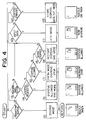
- Each section of the sectioned area 22 has an area 23a showing a number of the concerned dispenser, an area 23b showing a fuel flow volume and an area 23c showing situation or state of the concerned dispenser at the present, i.e. "Nozzle on Hook”, “Nozzle Taken”, “Dispensation Allowed”, “Now Dispensing", “Emergent Stop” and the like respectively in the form of symbols understandable at a glance as shown in Fig. 4.
- a memory or memories 41, 42 in the microcomputer 40 which have stored fuel flow volume are shown as explained later.
- Informations common to the all dispensers inclusive of the fuel volume of any of the dispensers which has finished its fuelling may be shown by request on the area 26 below the eight panel sections.
- the control device 20 is provided further therebelow with a key board 28 which has switches 28a-28c and a ten-key board 28d.
- the control device 20 has also a printer 29 for issuing a payment slip.
- First switch 28a is for selecting either of the two memories, second one 28b for setting printing means to issue the payment slip, and third one 28c for stopping all dispensers in emergency, e.g. when finding anyone smoking.
- Fig. 2 showing arrangement of elements in the microcomputer 40 of the control device 20 of the invention
- data as to the dispensed fuel flow volume is given by the dispensation controller 6 and sent through the line 10 (Fig. 1) to be stored in a first or second memory 41, 42.
- the two memories are provided that any dispenser having just finished its fuelling may be used at once by the second customer if the dispensed fuel volume is stored in the other memory.
- three or more memories may be provided if necessary.
- sectioned area 22 of the display panel 21 having eight sections is constructed also as a touch sensitive panel as said in the above so that, when touching any section of the panel with a finger, e.g. section "1", section judging means 45 connected therewith receive a signal therefrom so as to identify the number and give a signal to command output means 46 and symbol judging means 47.
- the symbol judging means 47 on receiving a signal from the section judging means 45 and the controller 6, selects one of the symbols stored in a symbol memory 48, which is shown on the area 23c of a section of the display 21 through display driving means 44.
- the command output means 46 on receiving a signal from the section judging means 45, gives a command through the line 10 to the controller 6 of the concerned dispenser (e.g. dispenser I) by taking account of a signal given by the symbol judging means 45 which represents a current state of the dispenser.
- the supplied signal is transmitted to the symbol judging means 47 through a line 50.
- Symbol judging means 47 on receiving the signal selects the symbol corresponding to "Nozzle Taken” from symbol storing means 48 so as to correspondingly actuates means 44 for driving the display 21, whereby the symbol for the second mode is indicated on the area 23c of the display panel section "1" which is for the dispenser I (Fig. 4, Step 2).
- the controller 6 When the signal for allowing dispensation is received (Fig. 3, Step 3), the controller 6 energizes the motor 2 for driving the pump 1 and sets the indicator 8 to "zero" (Fig. 3, Step 4). When the customer actuates the nozzle trigger to start fuelling, the controller calculates the fuel flow volume moment by moment in reference to pulse signals from the transmitter 5, the result of which is shown on the indicator 8 and sent to the control device 20 through the line 10 (Fig. 4, Step 10).
- the signal of fuel flow volume from the line 10 is sent to the display 21 through the line 50, the symbol judging means 47 and the display driving means 44 to be indicated on the area 23b of the display panel section "1" and, at the same time, the symbol on the area 23c is turned to the fourth mode, "Now Dispensing" (Fig. 4, Step 11).
- the signal is also sent to either the first memory 41 or the second memory 42 which stores no data and vacant.
- the control device 20 When the worker feels any danger to touch the section "1" of the touch sensitive panel 21 (Fig. 4, Step 3), the control device 20 outputs a signal for stopping dispensation of the concerned dispenser. In view of that the state is "Now Dispensing" (Fig. 4, Step 6) at that moment, the symbol is changed to one corresponding to "Emergent Stop” which is shown on the area 23c (Fig. 4, Step 7).
- the controller 6 of the dispenser I receives the corresponding signal from the control device 20 (Fig. 3, Step 5), the pump motor 2 is stopped (Fig. 3, step 6).
Landscapes
- Engineering & Computer Science (AREA)
- Physics & Mathematics (AREA)
- Mathematical Physics (AREA)
- Theoretical Computer Science (AREA)
- Mechanical Engineering (AREA)
- Loading And Unloading Of Fuel Tanks Or Ships (AREA)
- Management, Administration, Business Operations System, And Electronic Commerce (AREA)
Claims (8)
- Steuervorrichtung zur Steuerung einer Mehrzahl von Kraftstoff-Zapfstellen, miteinem Sichtanzeigefeld (21), das auch als berührungsempfindliches Feld ausgebildet und in Abschnitte unterteilt ist, deren Anzahl derjenigen der Kraftstoff-Zapfstellen (I, II...) entspricht, undeinem Mikrocomputer (40), der ein Mittel (47) aufweist, um Symbole zu beurteilen, die verschiedene Zustände der betreffenden Zapfstelle unter Bezugnahme auf Signale von der Zapfstelle und dem betreffenden berührungsempfindlichen Feldabschnitt darstellen,einem Mittel (44), das zum Treiben des Sichtanzeigefeldes vorgesehen und mit dem genannten Beurteilungsmittel (47) so verbunden ist, daß ein entsprechend beurteiltes Symbol auf dem betreffenden Anzeigefeldabschnitt angezeigt werden kann, undeinem Mittel (46), um einen Befehl, welcher einem durch Berühren des berührungsempfindlichen Feldabschnittes eingegebenen Signal entspricht, an die betreffende Zapfstelle auszugeben,wobei der Mikrocomputer (40) ein Speichermittel (41, 42) aufweist, um ein Krafstoffvolumen zu speichern, das durch die Krafstoff-Zapfstellen abgegeben worden ist,
dadurch gekennzeichnet, daß das Speichermittel (41, 42) zwei oder mehr Speicher beinhaltet, von denen jeder dazu eingerichtet ist, ein durch eine Krafstoff-Zapfstelle abgegebenes Krafstoffvolumen zu speichern, so daß diese Kraftstoff-Zapfstelle für eine weitere Abgabe unter Benutzung eines weiteren gelöschten oder leeren Speichers benutzt werden kann. - Steuervorrichtung wie in Anspruch 1 angegeben, bei der das genannte Sichtanzeigefeld (21) einen in Abschnitte geteilten Bereich (22), welcher in eine Mehrzahl von Abschnitten unterteilt ist, die Zapfstellen entsprechen, sowie einen gemeinsamen Bereich (26) besitzt, um Betankungsdaten einer bezeichneten Zapfstelle in größerem Maßstab anzuzeigen.
- Steuervorrichtung wie in Anspruch 1 oder Anspruch 2 angegeben, bei der die Daten eines sich vergrößernden Krafstoffvolumens, die augenblicklich von einer Kraftstoff-Zapfstelle (I, II...) übertragen werden, einerseits in dem Speicher (41 oder 42) gespeichert und andererseits auf dem betreffenden Anzeigefeldabschnitt durch das Beurteilungsmittel (47) und das Anzeigefeld - Treibermittel (44) angezeigt werden.
- Steuervorrichtung wie in Anspruch 1 angegeben, bei der jeder Anzeigefeldabschnitt Bereiche (23a, 23c, 23b, 23d) aufweist, die jeder die Zapfstellennummer, sämtliche der Symbole, die einen gegenwärtigen Zustand der betrachteten Zapfstelle darstellen, das abgegebene Krafstoffvolumen sowie die Speichereinrichtung zeigen.
- Steuervorrichtung wie in Anspruch 1 angegeben, bei der die genannten Symbole, die auf dem betreffenden Anzeigefeldabschnitt anzuzeigen und auf einen Blick verständlich sind, "Zapfpistole am Haken", was den Normalzustand bedeutet, "Zapfpistole abgenommen", was den Zustand bedeutet, wo die betreffende Zapfstelle darauf wartet, abgabefähig gemacht zu werden, "Abgabe gestattet", was einen Zustand bedeutet, wo die betreffende Zapfstelle abgabefähig gemacht wurde, "jetzt Abgabe" und "Nothalt" darstellen.
- Steuervorrichtung wie in Anspruch 4 angegeben, bei der der Mikrocomputer (40) außerdem ein Abschnittbeurteilungsmittel (45) aufweist, um eine Berührung auf dem betreffenden Anzeigefeldabschnitt zu erkennen, und das Abschnittbeurteilungsmittel (45), das Symbolbeurteilungsmittel (47) und das Symbolspeichermittel (48) jeweils miteinander zusammenwirken, so oft der Anzeigefeldabschnitt berührt wird, um einen gegebenen Zustand der betreffenden Zapfstelle von "Zapfpistole abgenommen" in "Abgabe gestattet", von "jetzt Abgabe" in "Nothalt" oder von "Nothalt" in "Abgabe gestattet" umzuändern, während das Symbolbeurteilungsmittel (47) und das Symbolspeichermittel (48) miteinander zusammenwirken, so oft das Symbolbeurteilungsmittel ein Signal von der betreffenden Zapfstelle erhält, um einen gegebenen Zustand der betreffenden Zapfstelle von "Zapfpistole am Haken" in "Zapfpistole abgenommen", von "Abgabe gestattet" in "jetzt Abgabe", von "jetzt Abgabe" in "Abgabe gestattet" oder von "Abgabe gestattet" in "Zapfpistole am Haken" umzuändern.
- Steuervorrichtung wie in Anspruch 1 angegeben, bei der der Mikrocomputer (40) außerdem ein Speicherauswählmittel (43) aufweist, das mit dem Speichermittel (41, 42) einerseits und mit dem Anzeigefeldtreibermittel (44) und einem Zahlbelegzettel-Ausgabemittel (49) andererseits verbunden ist, um die Daten des Speichermittels (41, 42) auf das Anzeigefeldtreibermittel (44) zu übertragen, um einen Anzeigefeldbereich (26) zu treiben, der als Teil des Sichtanzeigefeldes (21) ausgebildet ist, um die Daten anzuzeigen, und auf das Zahlbelegzettel-Ausgabemittel (49) zu übertragen, um einen Drucker (29) zu treiben, wobei das genannte Speicherauswählmittel (43) außerdem mit einem ersten Schalter (28a) für das Auswählen eines der Speicher (41, 42), und einem zweiten Schalter (28b) für das Treiben des Speicherauswählmittels (43) verbunden ist, wobei der zweite Schalter (28b) auch mit dem Zahlbelegzettel-Ausgabemittel (49) verbunden ist, um letzteres zu treiben, wodurch, wenn eine der Zapfstellen, die die Abgabetätigkeit beendet hat, durch Betätigen einer 10-Tasten-Tastatur (28d), die an der Steuervorrichtung (20) vorgesehen ist, bezeichnet wird und der betreffende eine der Speicher ausgewählt wird, indem der erste Schalter betätigt wird, die Daten in dem ausgewählten Speicher durch das Speicherauswählmittel (43) zu dem Anzeigefeldtreibermittel (44) übertragen werden, um die Daten auf dem Anzeigefeldbereich (26) anzuzeigen, und daß dann, wenn der zweite Schalter (28b) betätigt wird, um das Zahlbelegzettel-Ausgabemittel (29) zu betätigen, ein Zahlbelegzettel mit den darauf richtig aufgedruckten Daten mittels des Druckers ausgegeben wird und die Daten in dem ausgewählten Speicher gelöscht werden.
- Steuervorrichtung wie in Anspruch 1 angegeben, außerdem einen dritten Schalter (28c) aufweisend, um sämtliche Zapfstellen im Notfall stillzusetzen.
Applications Claiming Priority (2)
| Application Number | Priority Date | Filing Date | Title |
|---|---|---|---|
| JP35026991A JP2682314B2 (ja) | 1991-12-09 | 1991-12-09 | 給油機制御装置 |
| JP350269/91 | 1991-12-09 |
Publications (2)
| Publication Number | Publication Date |
|---|---|
| EP0546782A1 EP0546782A1 (de) | 1993-06-16 |
| EP0546782B1 true EP0546782B1 (de) | 1996-10-09 |
Family
ID=18409362
Family Applications (1)
| Application Number | Title | Priority Date | Filing Date |
|---|---|---|---|
| EP92311129A Expired - Lifetime EP0546782B1 (de) | 1991-12-09 | 1992-12-07 | Anordnung zur Steuerung einer Anzahl von Zapfsäulen |
Country Status (8)
| Country | Link |
|---|---|
| EP (1) | EP0546782B1 (de) |
| JP (1) | JP2682314B2 (de) |
| KR (1) | KR960006839B1 (de) |
| CA (1) | CA2084458C (de) |
| DE (1) | DE69214407T2 (de) |
| DK (1) | DK0546782T3 (de) |
| ES (1) | ES2095418T3 (de) |
| MY (1) | MY111052A (de) |
Families Citing this family (8)
| Publication number | Priority date | Publication date | Assignee | Title |
|---|---|---|---|---|
| ES2123679T3 (es) * | 1994-04-16 | 1999-01-16 | Scheidt & Bachmann Gmbh | Dispositivo para el suministro de carburantes liquidos. |
| EP2201475B1 (de) | 2007-10-10 | 2020-07-29 | Gilbarco Inc. | System und verfahren zur kontrolle sicherer und unsicherer inhalte bei einem ausgabe- oder verkaufsgerät |
| AU2011285794B2 (en) * | 2010-08-03 | 2014-08-28 | Gilbarco Inc. | Fuel dispenser application framework |
| BR112013027211A2 (pt) | 2011-04-22 | 2017-01-03 | Pepsico Inc | Sistema de fornecimento de bebidas com capacidade de mídia social |
| WO2013067020A1 (en) | 2011-11-01 | 2013-05-10 | Stephen Lim | Dispensing system and user interface |
| GB2498920A (en) * | 2011-12-01 | 2013-08-07 | Barchester Group Ltd | Controlling authorisation of supply of fuel to a vehicle |
| US10207912B2 (en) | 2014-11-07 | 2019-02-19 | Knappco Corporation | Crossover protection system graphical user interfaces |
| MX2020003800A (es) | 2017-10-09 | 2020-08-03 | Knappco Llc | Sistemas de control para vehiculos de entrega de productos liquidos. |
Citations (1)
| Publication number | Priority date | Publication date | Assignee | Title |
|---|---|---|---|---|
| JPS5952366A (ja) * | 1982-09-18 | 1984-03-26 | Tokyo Tatsuno Co Ltd | 給油所用販売デ−タ入出力装置 |
Family Cites Families (4)
| Publication number | Priority date | Publication date | Assignee | Title |
|---|---|---|---|---|
| US4589069A (en) * | 1982-09-18 | 1986-05-13 | Tokyo Tatsuno Co., Ltd. | Data input/output system for gasoline stations |
| US4630754A (en) * | 1983-10-15 | 1986-12-23 | Tokico Ltd. | Fuel supply system |
| JPS62145355A (ja) * | 1985-12-19 | 1987-06-29 | Tokico Ltd | Pos端末機 |
| CA1301929C (en) * | 1987-08-06 | 1992-05-26 | Peter William Hollidge | Interactive pump system |
-
1991
- 1991-12-09 JP JP35026991A patent/JP2682314B2/ja not_active Expired - Fee Related
-
1992
- 1992-12-03 CA CA002084458A patent/CA2084458C/en not_active Expired - Fee Related
- 1992-12-04 MY MYPI92002226A patent/MY111052A/en unknown
- 1992-12-07 DK DK92311129.8T patent/DK0546782T3/da active
- 1992-12-07 DE DE69214407T patent/DE69214407T2/de not_active Expired - Fee Related
- 1992-12-07 EP EP92311129A patent/EP0546782B1/de not_active Expired - Lifetime
- 1992-12-07 ES ES92311129T patent/ES2095418T3/es not_active Expired - Lifetime
- 1992-12-08 KR KR1019920023574A patent/KR960006839B1/ko not_active Expired - Fee Related
Patent Citations (1)
| Publication number | Priority date | Publication date | Assignee | Title |
|---|---|---|---|---|
| JPS5952366A (ja) * | 1982-09-18 | 1984-03-26 | Tokyo Tatsuno Co Ltd | 給油所用販売デ−タ入出力装置 |
Also Published As
| Publication number | Publication date |
|---|---|
| EP0546782A1 (de) | 1993-06-16 |
| CA2084458A1 (en) | 1993-06-10 |
| JPH05162793A (ja) | 1993-06-29 |
| MY111052A (en) | 1999-08-30 |
| DK0546782T3 (da) | 1997-03-10 |
| KR960006839B1 (ko) | 1996-05-23 |
| ES2095418T3 (es) | 1997-02-16 |
| DE69214407T2 (de) | 1997-04-30 |
| CA2084458C (en) | 2002-02-05 |
| KR930012565A (ko) | 1993-07-20 |
| DE69214407D1 (de) | 1996-11-14 |
| JP2682314B2 (ja) | 1997-11-26 |
Similar Documents
| Publication | Publication Date | Title |
|---|---|---|
| US3949207A (en) | Installation for the delivery of liquids | |
| US4625275A (en) | Apparatus for dispensing money orders | |
| US5361216A (en) | Flow signal monitor for a fuel dispensing system | |
| US4250550A (en) | Fuel delivery control system | |
| US4870596A (en) | Method and apparatus for dispensing money orders | |
| US5014212A (en) | Apparatus for dispensing money orders | |
| US4894784A (en) | Apparatus for dispensing money orders | |
| US4750130A (en) | Fuel delivery display and control system | |
| US4216529A (en) | Fluid dispensing control system | |
| CA2084458C (en) | Control device for a plurality of fuel dispensers | |
| US6068030A (en) | Fueling system | |
| JP3473644B2 (ja) | 給油装置 | |
| JP2979919B2 (ja) | 給油所データ処理装置 | |
| JP3346101B2 (ja) | 計量機 | |
| JP2925579B2 (ja) | 給油装置 | |
| JP2723550B2 (ja) | 計量機 | |
| JPH05338700A (ja) | 給油制御装置 | |
| JPH0610035B2 (ja) | 給油装置 | |
| KR100198699B1 (ko) | 급유장치 | |
| JPH0617151B2 (ja) | 給油装置 | |
| JP2586254B2 (ja) | 給油装置 | |
| KR0126408B1 (ko) | 급유장치 | |
| JPH0441116Y2 (de) | ||
| JPH10264995A (ja) | 給油所管理システム | |
| JP2575462B2 (ja) | 給油システム |
Legal Events
| Date | Code | Title | Description |
|---|---|---|---|
| PUAI | Public reference made under article 153(3) epc to a published international application that has entered the european phase |
Free format text: ORIGINAL CODE: 0009012 |
|
| AK | Designated contracting states |
Kind code of ref document: A1 Designated state(s): CH DE DK ES FR GB IT LI NL SE |
|
| 17P | Request for examination filed |
Effective date: 19931210 |
|
| 17Q | First examination report despatched |
Effective date: 19950227 |
|
| GRAG | Despatch of communication of intention to grant |
Free format text: ORIGINAL CODE: EPIDOS AGRA |
|
| GRAH | Despatch of communication of intention to grant a patent |
Free format text: ORIGINAL CODE: EPIDOS IGRA |
|
| GRAH | Despatch of communication of intention to grant a patent |
Free format text: ORIGINAL CODE: EPIDOS IGRA |
|
| GRAA | (expected) grant |
Free format text: ORIGINAL CODE: 0009210 |
|
| AK | Designated contracting states |
Kind code of ref document: B1 Designated state(s): CH DE DK ES FR GB IT LI NL SE |
|
| REF | Corresponds to: |
Ref document number: 69214407 Country of ref document: DE Date of ref document: 19961114 |
|
| ITF | It: translation for a ep patent filed | ||
| REG | Reference to a national code |
Ref country code: CH Ref legal event code: NV Representative=s name: LUCHS & PARTNER PATENTANWAELTE |
|
| ET | Fr: translation filed | ||
| REG | Reference to a national code |
Ref country code: ES Ref legal event code: FG2A Ref document number: 2095418 Country of ref document: ES Kind code of ref document: T3 |
|
| REG | Reference to a national code |
Ref country code: DK Ref legal event code: T3 |
|
| PLBE | No opposition filed within time limit |
Free format text: ORIGINAL CODE: 0009261 |
|
| 26N | No opposition filed | ||
| REG | Reference to a national code |
Ref country code: GB Ref legal event code: IF02 |
|
| PGFP | Annual fee paid to national office [announced via postgrant information from national office to epo] |
Ref country code: NL Payment date: 20071221 Year of fee payment: 16 Ref country code: DK Payment date: 20071204 Year of fee payment: 16 |
|
| PGFP | Annual fee paid to national office [announced via postgrant information from national office to epo] |
Ref country code: IT Payment date: 20071219 Year of fee payment: 16 |
|
| PGFP | Annual fee paid to national office [announced via postgrant information from national office to epo] |
Ref country code: SE Payment date: 20071212 Year of fee payment: 16 |
|
| PGFP | Annual fee paid to national office [announced via postgrant information from national office to epo] |
Ref country code: GB Payment date: 20071003 Year of fee payment: 16 Ref country code: FR Payment date: 20071031 Year of fee payment: 16 Ref country code: ES Payment date: 20080130 Year of fee payment: 16 Ref country code: CH Payment date: 20080128 Year of fee payment: 16 |
|
| PGFP | Annual fee paid to national office [announced via postgrant information from national office to epo] |
Ref country code: DE Payment date: 20071220 Year of fee payment: 16 |
|
| REG | Reference to a national code |
Ref country code: CH Ref legal event code: PL |
|
| REG | Reference to a national code |
Ref country code: DK Ref legal event code: EBP |
|
| EUG | Se: european patent has lapsed | ||
| GBPC | Gb: european patent ceased through non-payment of renewal fee |
Effective date: 20081207 |
|
| NLV4 | Nl: lapsed or anulled due to non-payment of the annual fee |
Effective date: 20090701 |
|
| REG | Reference to a national code |
Ref country code: FR Ref legal event code: ST Effective date: 20090831 |
|
| PG25 | Lapsed in a contracting state [announced via postgrant information from national office to epo] |
Ref country code: LI Free format text: LAPSE BECAUSE OF NON-PAYMENT OF DUE FEES Effective date: 20081231 Ref country code: DE Free format text: LAPSE BECAUSE OF NON-PAYMENT OF DUE FEES Effective date: 20090701 Ref country code: CH Free format text: LAPSE BECAUSE OF NON-PAYMENT OF DUE FEES Effective date: 20081231 |
|
| PG25 | Lapsed in a contracting state [announced via postgrant information from national office to epo] |
Ref country code: NL Free format text: LAPSE BECAUSE OF NON-PAYMENT OF DUE FEES Effective date: 20090701 Ref country code: GB Free format text: LAPSE BECAUSE OF NON-PAYMENT OF DUE FEES Effective date: 20081207 |
|
| PG25 | Lapsed in a contracting state [announced via postgrant information from national office to epo] |
Ref country code: DK Free format text: LAPSE BECAUSE OF NON-PAYMENT OF DUE FEES Effective date: 20090105 |
|
| REG | Reference to a national code |
Ref country code: ES Ref legal event code: FD2A Effective date: 20081209 |
|
| PG25 | Lapsed in a contracting state [announced via postgrant information from national office to epo] |
Ref country code: FR Free format text: LAPSE BECAUSE OF NON-PAYMENT OF DUE FEES Effective date: 20081231 Ref country code: ES Free format text: LAPSE BECAUSE OF NON-PAYMENT OF DUE FEES Effective date: 20081209 |
|
| PG25 | Lapsed in a contracting state [announced via postgrant information from national office to epo] |
Ref country code: SE Free format text: LAPSE BECAUSE OF NON-PAYMENT OF DUE FEES Effective date: 20081208 |
|
| PG25 | Lapsed in a contracting state [announced via postgrant information from national office to epo] |
Ref country code: IT Free format text: LAPSE BECAUSE OF NON-PAYMENT OF DUE FEES Effective date: 20081207 |