EP0546902A1 - Begrenzungsvorrichtung eines Flugzeugfahrwerkdämpfers und Dämpfer damit ausgerüstet - Google Patents
Begrenzungsvorrichtung eines Flugzeugfahrwerkdämpfers und Dämpfer damit ausgerüstet Download PDFInfo
- Publication number
- EP0546902A1 EP0546902A1 EP92403287A EP92403287A EP0546902A1 EP 0546902 A1 EP0546902 A1 EP 0546902A1 EP 92403287 A EP92403287 A EP 92403287A EP 92403287 A EP92403287 A EP 92403287A EP 0546902 A1 EP0546902 A1 EP 0546902A1
- Authority
- EP
- European Patent Office
- Prior art keywords
- annular valve
- housing
- clipping device
- main body
- orifices
- Prior art date
- Legal status (The legal status is an assumption and is not a legal conclusion. Google has not performed a legal analysis and makes no representation as to the accuracy of the status listed.)
- Withdrawn
Links
Images
Classifications
-
- B—PERFORMING OPERATIONS; TRANSPORTING
- B64—AIRCRAFT; AVIATION; COSMONAUTICS
- B64C—AEROPLANES; HELICOPTERS
- B64C25/00—Alighting gear
- B64C25/32—Alighting gear characterised by elements which contact the ground or similar surface
- B64C25/58—Arrangements or adaptations of shock-absorbers or springs
- B64C25/60—Oleo legs
-
- F—MECHANICAL ENGINEERING; LIGHTING; HEATING; WEAPONS; BLASTING
- F16—ENGINEERING ELEMENTS AND UNITS; GENERAL MEASURES FOR PRODUCING AND MAINTAINING EFFECTIVE FUNCTIONING OF MACHINES OR INSTALLATIONS; THERMAL INSULATION IN GENERAL
- F16F—SPRINGS; SHOCK-ABSORBERS; MEANS FOR DAMPING VIBRATION
- F16F9/00—Springs, vibration-dampers, shock-absorbers, or similarly-constructed movement-dampers using a fluid or the equivalent as damping medium
- F16F9/06—Springs, vibration-dampers, shock-absorbers, or similarly-constructed movement-dampers using a fluid or the equivalent as damping medium using both gas and liquid
- F16F9/061—Mono-tubular units
-
- F—MECHANICAL ENGINEERING; LIGHTING; HEATING; WEAPONS; BLASTING
- F16—ENGINEERING ELEMENTS AND UNITS; GENERAL MEASURES FOR PRODUCING AND MAINTAINING EFFECTIVE FUNCTIONING OF MACHINES OR INSTALLATIONS; THERMAL INSULATION IN GENERAL
- F16F—SPRINGS; SHOCK-ABSORBERS; MEANS FOR DAMPING VIBRATION
- F16F9/00—Springs, vibration-dampers, shock-absorbers, or similarly-constructed movement-dampers using a fluid or the equivalent as damping medium
- F16F9/06—Springs, vibration-dampers, shock-absorbers, or similarly-constructed movement-dampers using a fluid or the equivalent as damping medium using both gas and liquid
- F16F9/08—Springs, vibration-dampers, shock-absorbers, or similarly-constructed movement-dampers using a fluid or the equivalent as damping medium using both gas and liquid where gas is in a chamber with a flexible wall
- F16F9/088—Springs, vibration-dampers, shock-absorbers, or similarly-constructed movement-dampers using a fluid or the equivalent as damping medium using both gas and liquid where gas is in a chamber with a flexible wall comprising a gas spring with a flexible wall provided within the cylinder on the piston rod of a monotubular damper or within the inner tube of a bitubular damper
-
- F—MECHANICAL ENGINEERING; LIGHTING; HEATING; WEAPONS; BLASTING
- F16—ENGINEERING ELEMENTS AND UNITS; GENERAL MEASURES FOR PRODUCING AND MAINTAINING EFFECTIVE FUNCTIONING OF MACHINES OR INSTALLATIONS; THERMAL INSULATION IN GENERAL
- F16F—SPRINGS; SHOCK-ABSORBERS; MEANS FOR DAMPING VIBRATION
- F16F9/00—Springs, vibration-dampers, shock-absorbers, or similarly-constructed movement-dampers using a fluid or the equivalent as damping medium
- F16F9/32—Details
- F16F9/34—Special valve constructions; Shape or construction of throttling passages
- F16F9/348—Throttling passages in the form of annular discs or other plate-like elements which may or may not have a spring action, operating in opposite directions or singly, e.g. annular discs positioned on top of the valve or piston body
- F16F9/3485—Throttling passages in the form of annular discs or other plate-like elements which may or may not have a spring action, operating in opposite directions or singly, e.g. annular discs positioned on top of the valve or piston body characterised by features of supporting elements intended to guide or limit the movement of the annular discs
Definitions
- the present invention relates to the shock absorbers of landing gear of aircraft, in particular of helicopters, and more particularly the means provided for clipping of the efforts collected in the event of a crash landing (situation commonly called "crash").
- the shock absorber is articulated at its lower end on the pendulum and at its upper end on the structure of the helicopter, being arranged substantially vertically, so that the reaction of the ground tends, by means of the wheel or associated wheels, to pivot the pendulum and to push the rod of the shock absorber into the body of said shock absorber.
- shock absorbers Some of which include means for decompressing forces in the event of excessive overpressure.
- the shock absorbers used are of the type comprising a main body in which slides a piston rod, with on the one hand a hydraulic damping means with diaphragm, intervening under normal conditions of use, and on the other hand, a two-chamber energy absorption means containing a gas under pressure, one of which is at low pressure and the other at high pressure, intervening during a crash landing (so-called "crash" situation ).
- Means of effort clipping eventually provided are either merged with a component of the shock absorber (for example a separating piston delimiting the volume of the high-pressure chamber), or constituted by a pressure relief valve specially designed to intervene in the event of overpressure caused by a depression at high speed of the damper rod in the body of the latter.
- a component of the shock absorber for example a separating piston delimiting the volume of the high-pressure chamber
- a pressure relief valve specially designed to intervene in the event of overpressure caused by a depression at high speed of the damper rod in the body of the latter.
- a shock absorber with a main body arranged at the bottom and a piston rod arranged at the top, the main body widening below at the level of a high pressure chamber delimited by a separating piston surmounted of a volume of oil.
- the piston rod is hollow, to delimit an upper low-pressure chamber adjacent to a volume of oil in communication, by a rolling device (orifice in a partition) provided at the lower end of the rod, with the oil contained in the main body chamber.
- the vertical reaction of the soil causes a re-entry of the rod into the main body, which is accompanied by a compression of the gas volume contained in the low pressure chamber, this re-entry movement being slowed down by the rolling device.
- the pressure induced by the rolling device is communicated by the oil from the cylinder to the separating piston, and, like the pressure then applied to the piston separator exceeds the inflation pressure of the high pressure chamber, said piston descends by compressing said chamber.
- this is a "natural" force clipping effected by the separating piston.
- shock absorber lends itself poorly to large retraction strokes.
- the oil flows both upwards (passing through the rolling hole to enter the hollow rod) and downwards (passing through the enlargement of the main body to lower the piston separator), so that hydrodynamic disturbances can be generated under certain impact conditions.
- a shock absorber with a main body arranged at the bottom and a piston rod arranged at the top, the main body comprising at the lower end a high pressure chamber which is adjacent, by a flexible separation membrane. able to bear a rigid perforated support integral with said body, to a low pressure chamber, as well as a rolling device braking the movements of the rod in the main body by rolling the fluid contained in said body and adjacent to the low pressure chamber .
- the piston rod is hollow, and receives a separating piston delimiting two hydraulic chambers.
- shock absorber is described in document FR-A-2,608,242.
- the rolling device (which is associated with a cylindrical-conical tube forming an energy absorber by plastic deformation) comprises on the one hand a plurality of small orifices of passage arranged in a circular pattern, which intervene at normal driving-in speeds of the rod, and on the other hand a central overpressure valve, the rod of which passes through a central passage opening of larger cross section than that of the above-mentioned orifices, this valve being held in the closed position by conical elastic washers stacked on the rod of said valve, but intervening in the event of a sudden depression of the rod, with high speed, in the body of the damper, in order to obtain a larger passage section and to avoid damaging overpressures.
- the rolling device has drawbacks or limitations which are inherent in the very arrangement of the components which constitute it: the valve-stem and conical elastic washer assembly has a relatively high inertia and uses friction which it is difficult to minimize, which excludes very short response times, not to mention the possible risks of jamming of the valve stem; in addition, the passage section of the central opening remains limited (one cannot reduce the diameter of the valve stem too much under penalty of weakening it, and one cannot choose a diameter too large for the central opening under penalty of excessively reduce the mechanical resistance of the fixed part concerned).
- the object of the invention is to design means for clipping forces which are more efficient than the known means mentioned above, and which are capable of intervening with very short response times in the event of high impact speeds. (crash landing or "crash" situation).
- the object of the invention is also to design clipping means allowing both a significant clipping of the forces, and a precise control of the associated pressure drop in order to control the transmitted forces.
- the object of the invention is also to provide a device for clipping forces, the structure of which is simple and of reasonable manufacturing cost, while being integrable with shock absorbers of conventional design.
- the bottom of the housing has a plurality of small rolling orifices distributed around the axis of said bottom, and a plurality of orifices with a large passage section, arranged concentrically around said rolling orifices.
- the orifices with a large passage section are angularly distributed around the axis of the bottom of the housing, and open into a common annular chamber which is closed by the annular valve.
- the annular valve is made in the form of a flat annular washer, as light as possible, arranged around a central washer loaded by an associated return spring for closing the small rolling orifices, said central washer with small through holes for flash rolling.
- the elastic return member associated with the annular valve has a considerably higher stiffness than that of the return spring associated with the central washer.
- the elastic return member associated with the annular valve is produced in the form of a disc spring having a central passage opening, with an inner edge in abutment on said annular valve, and an outer edge in abutment against an associated collar of the housing.
- the assembly constituted by the annular valve and the disc spring has a minimum mass to allow very rapid opening of said annular valve.
- the inner and outer bearing edges of the disc spring are shaped to limit the frictional forces during the opening of the annular valve.
- the inner and outer bearing edges of the disc spring form toric beads. These support beads may have come in one piece with the remaining part of the disc spring, which is then produced in a monolithic form, or alternatively be constituted by added O-rings.
- the support flange is interrupted by lateral openings of the housing, so that the hydraulic fluid can flow, during the opening of the annular valve, both through the central opening of the spring- disc, and through said lateral openings passing around said disc spring.
- the invention also relates to an aircraft landing gear damper, in particular for a helicopter, comprising a main body in which slides a piston rod, with on the one hand a hydraulic damping means with diaphragm, intervening during normal conditions of use, and on the other hand a means of energy absorption with two chambers containing a gas under pressure, one of which is at low pressure and the other at high pressure, intervening during a landing in disaster, said shock absorber being remarkable in that it comprises a force clipping device having at least one of the aforementioned characteristics, device whose housing is fixed in the main body, the bottom of said housing delimiting on the one hand a hydraulic fluid chamber with the end face of the rod- piston, and on the other hand surmounted by a volume of hydraulic fluid to which the low pressure chamber is adjacent, said low pressure chamber being moreover delimited by a separating piston which also serves to delimit the adjacent high pressure chamber.
- the piston rod is arranged at the bottom and the main body at the top, said piston rod being articulated lower on a component of the landing gear and said main body being articulated higher on the structure of the aircraft.
- the bottom of the housing constitutes an end-of-travel stop for the piston rod during the retraction thereof in a crash landing situation.
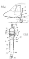
- FIG. 1 makes it possible to distinguish a shock absorber 100 with force clipping device according to the invention, here equipping a landing gear 11, of the pendulum type, of a helicopter 10.
- the landing gear 11 comprises a balance 12, articulated at its upper end 13 on the structure of the helicopter 10, and supporting at its other end one or more wheels 14.
- the damper 100 comprises a main body 101 in which slides a piston rod 103, the main body 101 being here arranged at the top of the shock absorber and being articulated at 16 by an associated swivel end piece on the structure of the helicopter, while the piston rod 102, arranged at the bottom of said shock absorber, is articulated below at 15, by an associated swivel end, on the balance 12 of the landing gear.
- the shock absorber 100 of the landing gear is preferably substantially vertical.
- FIG. 2 makes it possible to better distinguish the structure of the shock absorber 100 equipping the helicopter landing gear shown in FIG. 1.
- the shock absorber 100 comprises a main body 101 whose axis is denoted X, in which slides a piston rod 102 which is preferably full.
- the piston rod 102 slides in the lower part 109 of the main body 101, being guided by a smooth shoulder 107 provided at the lower end of the main body 101, the piston rod 102 comprising an associated main part 103, one end 104 of which is arranged in swivel end for an articulation link on the balance of the landing gear, while the other end 105 is arranged in the shape of a piston.
- the main body 101 comprises an intermediate part 110 associated with the maintenance of a functional assembly 200 forming both a diaphragm and a force-limiting valve, the structure of which will be described in more detail with reference to FIG. 3.
- the part Intermediate 110 of the main body 101 has for this purpose a lower shoulder 111, and an upper shoulder 112 ensuring the axial maintenance of the above-mentioned functional assembly 200.
- the main body 101 is finally extended by an upper portion 113 which ends in a swivel end piece 114 associated with the articulation of the main body on the structure of the helicopter.
- a chamber 118 is delimited below by the upper face 106 of the piston rod 102, and above by the functional unit 200.
- This chamber 118 is occupied by a corresponding volume of hydraulic fluid.
- the functional assembly 200 is on the other hand surmounted by a volume 119 of hydraulic fluid, the free surface of which delimits below a chamber 121 containing a pressurized gas (generally nitrogen), which is at low pressure, said chamber being delimited above by a separating piston 115 and the associated seal 108.
- the separating piston 115 scrapes the interior surface of the upper portion 113 of the main body 101, which makes it possible to delimit an adjacent chamber 122 also containing a gas under pressure, such as nitrogen, but at high pressure.
- the pressure prevailing in the low pressure chamber 121 is lower than that prevailing in the high pressure chamber 122, so that the separating piston 115 remains supported on a flange 116 formed for this purpose inside the upper part 113 of the main body 101.
- the flange 116 thus ensures the position in the resting state of the separating piston 115 under the force of the pressure differences between the high pressure chambers 122 and low pressure 121.
- a valve 120 ensures inflation of high-pressure gas in chamber 122.
- low-pressure chamber 121 it is delimited above by the separating piston 115 (and the associated seal 108), and below by the hydraulic fluid, the level is adjusted by an associated valve 117. This latter valve 117 is also used for inflating the low-pressure chamber 121 with nitrogen.
- the hydraulic fluid contained in the chamber 118 is partly forced through the functional assembly 200, and more precisely through the diaphragm part of said assembly.
- the volume of nitrogen in the low pressure chamber 121 is then reduced, and the pressure in said chamber increases at the same time as the speed of the piston rod 102 decreases.
- the high pressure chamber 122 therefore does not intervene in the context of such normal operation, the pressure threshold of the high pressure chamber not being reached.
- the return of the damper to the initial position is effected with a possible descent of the separating piston 115 until it rests on the associated flange 116, and with a rolling relaxation carried out by the diaphragm part of the functional assembly 200, of so as to brake the exit of the piston rod 102.
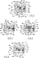
- FIGS. 4 and 5 respectively illustrate a normal operating mode and a "crash" operating mode.
- the assembly 200 comprises a housing 201 forming a partition for the main body 101 of the shock absorber, said housing having a bottom 202 whose central part includes a diaphragm 210 with small rolling orifices 211 whose axes 212 are distributed around the axis X of said bottom (which coincides with the main axis of the damper), each of these small orifices extending from the lower face 203 of the bottom of the housing, to an upper opening delimited by two concentric shoulders 213, 214.
- a central washer 215, loaded by an associated return spring 216, is provided for the simultaneous closing of the small orifices 211.
- a central bolt 217 passing through the bottom 202 of the housing by a central bore 218 thereof, ensures both the guiding of the central washer 215 during the movements of the latter, and the holding in place of the associated return spring 216.
- the central washer 215 finally has a plurality of small holes 219, formed opposite the rolling orifices 211 (but with a passage section smaller than that of said orifices), these small holes being associated with the rolling of the hydraulic fluid in expansion.
- the functional assembly 200 comprises a means for clipping forces 220, which essentially consists of an annular valve 225 arranged around the diaphragm 210, said valve allowing, when it is open , to pass in a very short time a large volume of hydraulic fluid, and by an elastic return member 226 holding the annular valve 225 in the closed position, said return member authorizing the opening of said valve from a predetermined threshold.
- the bottom 202 of the housing 201 thus comprises a plurality of small rolling orifices 211 distributed around the axis X of said bottom (the axes 212 of these orifices being inscribed on a cylinder of axis X), as well as a plurality of orifices 221 with a large passage section, the latter orifices being arranged around the rolling orifices 211 and concentric therewith. It is so provided a plurality of orifices 221 whose axes 222 are then inscribed on another cylinder of axis X.
- orifices 221 of circular section or not, the number and the section of these orifices being chosen as a function of the flow rate that one wishes to obtain during the intervention of these force clipping members.
- a set of four to six rolling orifices 211 will be provided, for example, having a diameter of the order of 3 mm, and as large a number as possible of orifices 221 with a large passage section, for example twelve orifices the diameter of which may reach comparatively 8 to 10 mm.
- the orifices 221 with a large passage section are preferably angularly distributed around the axis X of the bottom of the housing, and further open into a common annular chamber 227, which is delimited by two concentric shoulders 223, 224, and which is closed by the annular valve 225.
- Such an arrangement is favorable for obtaining the desired flow of a large volume of hydraulic fluid in a very short time, with very precise control of the pressure drop in the annular valve in order to control the forces transmitted.
- the annular valve 225 is preferably made in the form of a flat annular washer, as light as possible, arranged around the central washer 215 associated with the diaphragm part of the functional assembly 200. Such an embodiment is favorable for the 'obtaining a minimum inertia, this to allow a very rapid lifting of the annular force clipping valve, with a minimum response time.
- the annular valve 225 which is subjected to the action of the associated elastic return member 226, must however have sufficient rigidity so as not to harm the seal which it achieves during normal use of the damper.
- the central washer 215 and the annular washer 225 are preferably made of metal or any other equivalent synthetic material.
- the elastic return member 226 naturally constitutes a fundamental component of the force clipping system.
- This elastic return member has a considerably higher stiffness than that of the return spring 216 associated with the central washer 215, that is to say with the diaphragm function.
- high-strength steel will be used to make the return member 226.
- the structure of the elastic return member 226 illustrated here constitutes a particularly advantageous embodiment, insofar as it is compatible with obtaining a minimum mass for the annular valve - return member assembly, while allowing precise control of the pressure drop by the annular valve, which makes it almost negligible the parasitic effects downstream and upstream of said annular valve.
- the elastic return member 226 is in this case produced in the form of a disc spring, which has a central passage opening 230, with an inner edge 228 which is in abutment on the annular valve 225, and an edge 229 outside which is supported against an associated flange 205 of the housing 201.
- the disc spring 226 will be designed to have a predetermined law to ensure a law. efforts / race which is optimized according to the desired result. This predetermined law may be linear or conform to a curve determined by calculation.
- support flanges 228.1 and 229.1 constituted by added O-rings, said rings possibly being secured, by gluing or welding, at the level of associated grooves provided in the central part of the disc spring 226. It is therefore preferable to use metal ring rings.
- FIG. 3 also makes it possible to distinguish one of the lateral openings 204 of the housing 201, which interrupts the support flange 205 associated with the disc spring 226.
- Such lateral openings 204 favor obtaining a very high flow rate of hydraulic fluid for an extremely short time: in fact, the hydraulic fluid will be able to flow, when the annular valve 225 is opened, not only through the central opening 230 of the disc spring 226, but also through the or the lateral openings 204 of the housing 201 passing around the periphery of this disc spring.
- FIGS. 4 and 5 figures which illustrate said functional unit respectively under normal use conditions and in the event of a disaster or "crash" landing.
- FIG. 4 it is a landing at normal vertical speed, that is to say that the pressure exerted by the hydraulic fluid during the retraction of the piston rod in the main body of the shock absorber is sufficient to lift the central washer 215 against the action of the associated return spring 216, but insufficient to implement the force clipping members, that is to say lift the annular valve 225 against the action of the associated return disc spring 226.
- the hydraulic fluid therefore crosses the bottom 202 of the housing 201 through the small associated rolling orifices 211 which thus ensure a well-known diaphragm function.
- the flow of the hydraulic fluid is here diagrammed by the arrow 300.
- the flow of hydraulic fluid through the bottom 202 of the housing 201 thus takes place mainly through the orifices 221 with a large passage section, with a first flow bypassing the annular washer 225 on the inside of the latter (as shown by the arrow 301), then passing through the central opening 230 of the disc spring 226, and with another flow bypassing said annular valve from the outside thereof (as shown by arrow 302), then passing outside the disc spring 226 through the side openings 204 of the housing.
- Such an arrangement makes it possible to pass a large volume of oil (several liters) in an extremely short time (of the order of a tenth of a second) with very precise control of the pressure drop in the annular valve 225 in order to to control the transmitted forces.
- the bottom 202 of the housing 201 constitutes an end-of-travel stop for the piston rod 102, during the re-entry of the latter in a crash landing situation.
- Such a clipping device is also extremely reliable, insofar as the force clipping members present practically no risk of jamming, and have a minimum inertia which ensures extremely rapid lifting of the annular valve, and therefore an extremely satisfactory minimum response time in practice.
- the force clipping device finally has a simple structure, with a small number of constituent members, and this device can be easily integrated with shock absorbers of conventional design, and even shock absorbers initially free of clipping devices. efforts.
Landscapes
- Engineering & Computer Science (AREA)
- General Engineering & Computer Science (AREA)
- Mechanical Engineering (AREA)
- Aviation & Aerospace Engineering (AREA)
- Fluid-Damping Devices (AREA)
Applications Claiming Priority (2)
| Application Number | Priority Date | Filing Date | Title |
|---|---|---|---|
| FR919115371A FR2684957B1 (fr) | 1991-12-11 | 1991-12-11 | Dispositif d'ecretage pour amortisseur de train d'atterrissage d'aeronef, et amortisseur comportant un tel dispositif. |
| FR9115371 | 1991-12-11 |
Publications (1)
| Publication Number | Publication Date |
|---|---|
| EP0546902A1 true EP0546902A1 (de) | 1993-06-16 |
Family
ID=9419919
Family Applications (1)
| Application Number | Title | Priority Date | Filing Date |
|---|---|---|---|
| EP92403287A Withdrawn EP0546902A1 (de) | 1991-12-11 | 1992-12-04 | Begrenzungsvorrichtung eines Flugzeugfahrwerkdämpfers und Dämpfer damit ausgerüstet |
Country Status (5)
| Country | Link |
|---|---|
| US (1) | US5330132A (de) |
| EP (1) | EP0546902A1 (de) |
| JP (1) | JPH05262294A (de) |
| CA (1) | CA2084812A1 (de) |
| FR (1) | FR2684957B1 (de) |
Cited By (1)
| Publication number | Priority date | Publication date | Assignee | Title |
|---|---|---|---|---|
| EP1574427A1 (de) * | 2004-03-12 | 2005-09-14 | Messier-Dowty S.A. | Fahrwerk mit einem Gasbehälter und Wartungsverfahren dafür |
Families Citing this family (17)
| Publication number | Priority date | Publication date | Assignee | Title |
|---|---|---|---|---|
| JP3160618B2 (ja) * | 1997-01-28 | 2001-04-25 | 防衛庁技術研究本部長 | ヘリコプタ用降着装置 |
| US5944283A (en) * | 1997-12-05 | 1999-08-31 | Cartercopters, Llc | Crashworthy landing gear shock |
| US6168142B1 (en) * | 1998-03-25 | 2001-01-02 | Mcdonnell Douglas Helicopter Company | Hydraulic damper with elastomeric spring assembly |
| US6460664B1 (en) | 2000-05-22 | 2002-10-08 | Tenneco Automotive Inc. | Independently tunable variable bleed orifice |
| US6644445B2 (en) | 2001-11-19 | 2003-11-11 | Tenneco Automotive Operating Company Inc. | Floating port blocker |
| US7963509B2 (en) * | 2007-01-31 | 2011-06-21 | Fox Factory, Inc. | Travel control for a gas spring and gas spring having very short travel modes |
| FR2869016B1 (fr) * | 2004-04-19 | 2007-07-20 | Messier Dowty Sa Sa | Atterisseur a amortisseur trichambre |
| FR2884801B1 (fr) * | 2005-04-22 | 2008-11-14 | Eurocopter France | Atterrisseur auxillaire de nez, structure porteuse et aeronef a voilure tournante |
| FR2884802B1 (fr) * | 2005-04-22 | 2008-11-14 | Eurocopter France | Structure porteuse et aeronef a voilure tournante |
| US8020584B2 (en) * | 2005-05-03 | 2011-09-20 | Love Phillip W | Variable valve for impact dispersal device |
| FR2917371B1 (fr) * | 2007-06-15 | 2009-11-20 | Messier Dowty Sa | Amortisseur pour atterisseur d'aeronef |
| FR2959207B1 (fr) * | 2010-04-26 | 2012-04-20 | Eurocopter France | Systeme a absortion d'energie pour un atterisseur, et aeronef muni dudit systeme a absorption d'energie |
| JP6212337B2 (ja) * | 2013-09-13 | 2017-10-11 | Kyb株式会社 | 単筒型液圧緩衝器 |
| CN110406685B (zh) * | 2019-08-07 | 2024-11-26 | 龙岩学院 | 一种用于旋翼无人机与机械手快速安装拆卸的连接装置 |
| US11939045B2 (en) | 2022-04-27 | 2024-03-26 | The Boeing Company | Landing gear assembly for an aircraft, a landing gear system, and a method |
| GB2626193A (en) * | 2023-01-16 | 2024-07-17 | Airbus Operations Ltd | Improvements relating to VTOL aircraft |
| CN116692063B (zh) * | 2023-07-18 | 2026-03-27 | 深圳市博坦智能有限公司 | 一种无人机传动机构及无人机 |
Citations (4)
| Publication number | Priority date | Publication date | Assignee | Title |
|---|---|---|---|---|
| FR2102749A5 (de) * | 1970-08-14 | 1972-04-07 | Autoipari Kutato Intezet | |
| US4126212A (en) * | 1976-09-03 | 1978-11-21 | The Boeing Co. | Crash load attenuating valve for an aircraft landing gear shock strut |
| GB2132313A (en) * | 1982-12-10 | 1984-07-04 | Fokker Bv | Hydropneumatic shock absorber with serially disposed gas chambers |
| FR2608242A1 (fr) * | 1986-12-12 | 1988-06-17 | Aerospatiale | Amortisseur-verin, contre-fiche le comportant, et train d'atterrissage equipe d'une telle contre-fiche |
Family Cites Families (8)
| Publication number | Priority date | Publication date | Assignee | Title |
|---|---|---|---|---|
| FR2497896A1 (fr) * | 1980-08-29 | 1982-07-16 | Messier Hispano Sa | Amortisseur |
| GB8316722D0 (en) * | 1983-06-20 | 1983-07-20 | Laser Eng Dev Ltd | Apparatus for hydraulic damping |
| GB2147683B (en) * | 1983-09-24 | 1986-10-01 | Bilstein August Gmbh Co Kg | Shock absorber, with electromagnetically biased pressure responsive valve |
| FR2554415B1 (fr) * | 1983-11-09 | 1986-02-07 | Messier Hispano Sa | Atterrisseurs pour aeronef, notamment pour helicoptere |
| DE3832625C2 (de) * | 1987-10-13 | 1999-06-24 | Hauni Werke Koerber & Co Kg | Schwingungsdämpfer mit veränderbarer Dämpfungscharakteristik |
| GB2226620B (en) * | 1988-10-25 | 1992-11-04 | Tokico Ltd | Hydraulic damper |
| JPH0292154U (de) * | 1989-01-10 | 1990-07-23 | ||
| FR2651553B1 (fr) * | 1989-09-06 | 1991-12-13 | Sirven Jacques | Valve pour fluide hydraulique et amortisseur comportant une telle valve. |
-
1991
- 1991-12-11 FR FR919115371A patent/FR2684957B1/fr not_active Expired - Fee Related
-
1992
- 1992-12-02 US US07/984,521 patent/US5330132A/en not_active Expired - Fee Related
- 1992-12-04 EP EP92403287A patent/EP0546902A1/de not_active Withdrawn
- 1992-12-08 CA CA002084812A patent/CA2084812A1/fr not_active Abandoned
- 1992-12-10 JP JP4330617A patent/JPH05262294A/ja active Pending
Patent Citations (4)
| Publication number | Priority date | Publication date | Assignee | Title |
|---|---|---|---|---|
| FR2102749A5 (de) * | 1970-08-14 | 1972-04-07 | Autoipari Kutato Intezet | |
| US4126212A (en) * | 1976-09-03 | 1978-11-21 | The Boeing Co. | Crash load attenuating valve for an aircraft landing gear shock strut |
| GB2132313A (en) * | 1982-12-10 | 1984-07-04 | Fokker Bv | Hydropneumatic shock absorber with serially disposed gas chambers |
| FR2608242A1 (fr) * | 1986-12-12 | 1988-06-17 | Aerospatiale | Amortisseur-verin, contre-fiche le comportant, et train d'atterrissage equipe d'une telle contre-fiche |
Cited By (3)
| Publication number | Priority date | Publication date | Assignee | Title |
|---|---|---|---|---|
| EP1574427A1 (de) * | 2004-03-12 | 2005-09-14 | Messier-Dowty S.A. | Fahrwerk mit einem Gasbehälter und Wartungsverfahren dafür |
| FR2867451A1 (fr) * | 2004-03-12 | 2005-09-16 | Messier Dowty Sa | Atterisseur a reservoir de gaz et procedes de maintenance d'un tel atterisseur |
| US7204456B2 (en) | 2004-03-12 | 2007-04-17 | Messier-Dowty Sa | Landing gear having a gas vessel, and methods of maintaining such landing gear |
Also Published As
| Publication number | Publication date |
|---|---|
| US5330132A (en) | 1994-07-19 |
| JPH05262294A (ja) | 1993-10-12 |
| FR2684957A1 (fr) | 1993-06-18 |
| FR2684957B1 (fr) | 1994-03-04 |
| CA2084812A1 (fr) | 1993-06-12 |
Similar Documents
| Publication | Publication Date | Title |
|---|---|---|
| EP0546902A1 (de) | Begrenzungsvorrichtung eines Flugzeugfahrwerkdämpfers und Dämpfer damit ausgerüstet | |
| CA2148852C (fr) | Dispositif de securite pour systeme transporte a bord d'un vehicule, notamment d'un aeronef | |
| EP0072323B1 (de) | Mit einer Energieaufnahmevorrichtung durch plastische Verformung und/oder Kraftbegrenzung ausgerüstete Elemente, und Flugzeugfahrgestelle mit derartigen Elementen | |
| EP0275735B1 (de) | Landungsbein mit Dämpferheber und Flugzeugfahrgestelle, ausgerüstet mit einem derartigen Landungsbein | |
| EP0416987B1 (de) | Ventil für hydraulische Flüssigkeit und ein mit einem solchen Ventil ausgerüsteter Dämpfer | |
| EP0051506B1 (de) | Dämpferheber | |
| EP2048408B1 (de) | Stoßdämpfer eines Fahrzeugs | |
| CA2092490A1 (fr) | Atterrisseur relevable d'aerodynes, notamment pour helicopteres | |
| EP0014660B1 (de) | Dämpfer und Dämpfer-Kraftzylinder, insbesondere für Fahrgestelle von Flugzeugen | |
| EP0666967A1 (de) | Dämpfer für ein mechanisches system. | |
| FR2461852A1 (fr) | Perfectionnements aux amortisseurs et amortisseurs-verins notamment pour trains d'atterrissage d'aerodyne | |
| EP0564324A1 (de) | Dämpfer-Antriebszylinder für das Fahrwerk eines Flugzeuges, insbesondere für Hubschrauber | |
| EP0288377B1 (de) | Landungssystem eines Flugzeuges | |
| EP0274935B1 (de) | Stossdämpfer für das hydropneumatische Federungselement eines Kraftfahrzeugs | |
| EP1574427B1 (de) | Fahrwerk mit einem Gasbehälter und Wartungsverfahren dafür | |
| EP0332509B1 (de) | Stossdämpfer mit dynamischer Abdichtung | |
| CA2566241C (fr) | Dispositif d'amortisseur a deceleration asservie, et son application a l'amortissement de la colonne de direction escamotable d'un vehicule automobile | |
| EP3997356B1 (de) | Hydraulischer endanschlag für einen dämpfer | |
| EP0866924A1 (de) | Teleskopdämpfer mit einem laminatkanal | |
| FR2549445A1 (fr) | Dispositif de securite pour decomprimer des pneus d'avion | |
| EP3546789B1 (de) | Hydroelastischer stossdämpfer, und luftfahrzeug | |
| FR2472699A1 (fr) | Perfectionnements aux amortisseurs-verins | |
| FR2777058A1 (fr) | Dispositif de suspension et d'amortissement a deux combines suspension-amortisseur | |
| EP1332963A1 (de) | Fahrwerkstossdämpfer und Fahrwerk mit unabhängigen Fahrgestellstreben mit solchem Stossdämpfer | |
| WO1995023299A1 (fr) | Dispositif d'absorption d'energie par deformation plastique, notamment pour volant de direction de vehicule, et volant de direction equipe d'un tel dispositif |
Legal Events
| Date | Code | Title | Description |
|---|---|---|---|
| PUAI | Public reference made under article 153(3) epc to a published international application that has entered the european phase |
Free format text: ORIGINAL CODE: 0009012 |
|
| 17P | Request for examination filed |
Effective date: 19921208 |
|
| AK | Designated contracting states |
Kind code of ref document: A1 Designated state(s): DE GB IT NL |
|
| 17Q | First examination report despatched |
Effective date: 19940809 |
|
| 18D | Application deemed to be withdrawn |
Effective date: 19950124 |